 Kris Winer
From the CMWX1ZZABZ data sheet:
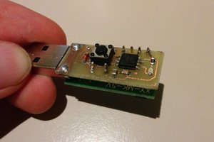
"Type ABZ is a new, compact, low cost, low power wide area network (LPWAN) wireless module that supports the LoRaWAN long range wireless protocol. This new stand-alone module measures just 12.5 x 11.6 x 1.76 mm, is constructed in a metal shielded package and comprises a Semtech SX1276 ultra long range spread spectrum wireless transceiver and an STMicro STM32L0 series ARM Cortex-M0+ 32 bit microcontroller (MCU). An integrated TCXO that has robust low drift thermal characteristics provides an accurate clock source for the RF transceiver."
It's a small module, and we have taken advantage of this to design compact boards that use very little power to do really interesting things. The STM32L082 MCU host is a Cortex M0+ operating at 4, 16, and 32 MHz, it manages the Sematech SX1276 LoRa radio modem and offers the user up to 19 GPIOs for controlling sensors and other peripheral devices like flash memory, SD card, displays, etc. There is a well-designed LoRaWAN stack for simple configuration of the LoRa radio for use with standard gateways and, for example, the Things Network.
In addition to three different CPU clock speeds, the STM32L082 is capable of several different low power modes including SLEEP, STOP (1.6 uA) and STANDBY (500 nA); there are a variety of tools to minimize power usage. The module offers the usual set of serial protocols including SPI, I2C, and UART, as well as analog pins with ADC and DAC. So far, we have designed three devices with embedded CMWX1ZZABZ hosts: Grasshopper Development Board, LoRaSensorTile, and Cricket Asset Tracker.
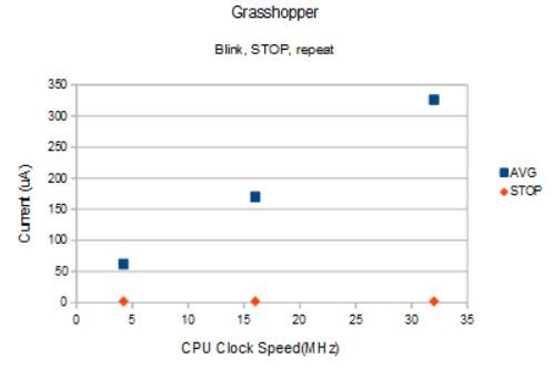
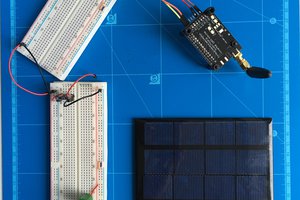
Grasshopper is a Teensy-sized (18 mm x 45 mm) development board which exposes all 19 of the CMWX1ZZABZ GPIOs as well as 3V3, GND, a VIN port for power input or battery voltage output and VREF for selecting the analog reference voltage if different from the default 3V3. The Grasshopper uses the NCV8170 3V3 150 mA LDO with quiescent current of just 500 nA to allow the lowest power consumption. The on-board chip antenna provides excellent LoRa transmission; there is also a uFl connector for an external antenna if desired. Grasshopper is the perfect way to develop your LoRa application on the breadboard. And because Grasshopper is open-source, you can use the Grasshopper design as a template for your own custom design suited to your application. Grasshopper is available for sale at Tindie.
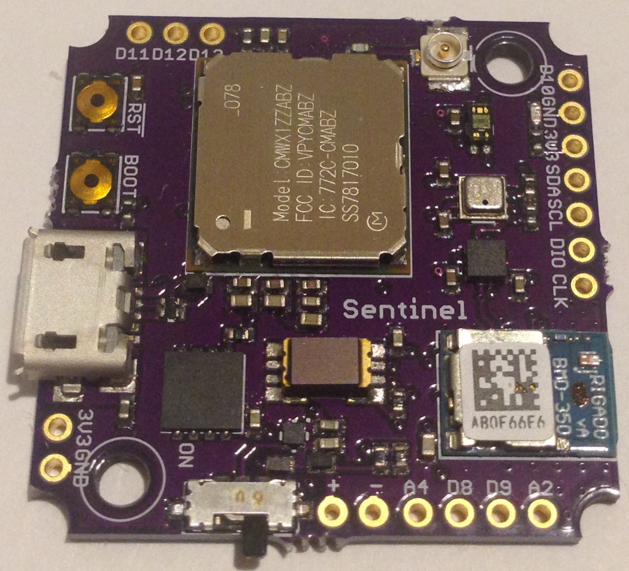
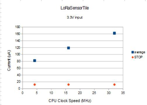
The LoRaSensorTile is designed in a different form factor than the Grasshopper and we have added a STBC08 LiPo battery charger, 16 MByte SPI NOR flash memory, BMA280 accelerometer, BME280 pressure/temperature/humidity sensors, as well as a VEML6040 RGBW ambient light sensor. The components have been chosen for ultra-low power operation; the LoRaSensorTile has a sleep current of just 12 uA. Total average power depends on sensor data rates and frequency of LoRaWAN transmission chosen but we expect with average use (store data to flash once per minute, send LoRa data once every ten minutes) the LoRaSensorTile will last more than a year on a single AAA battery.
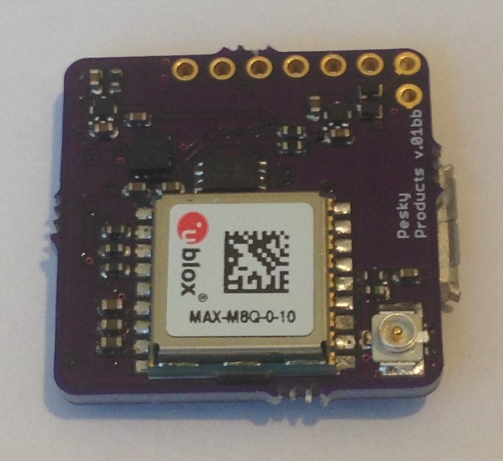
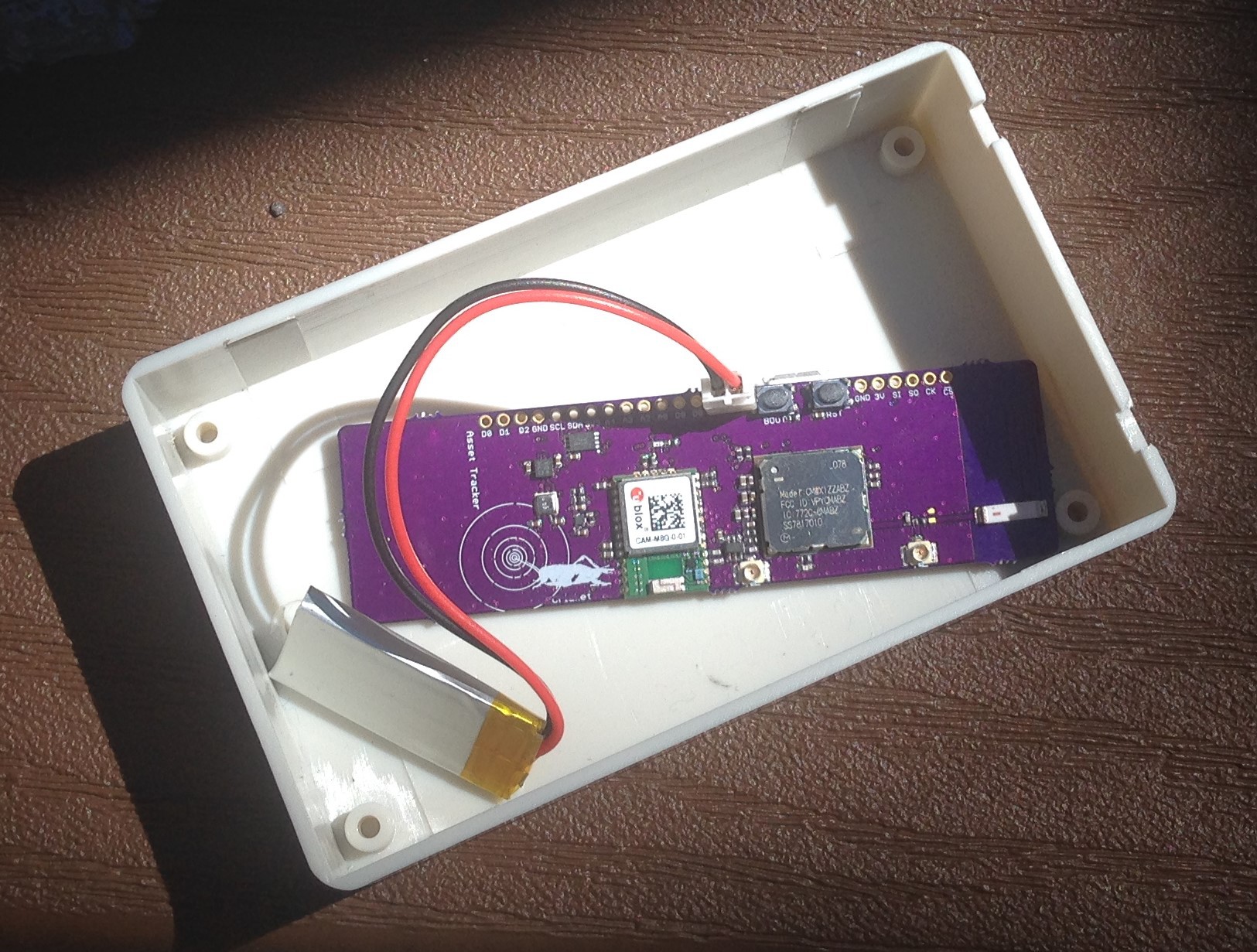
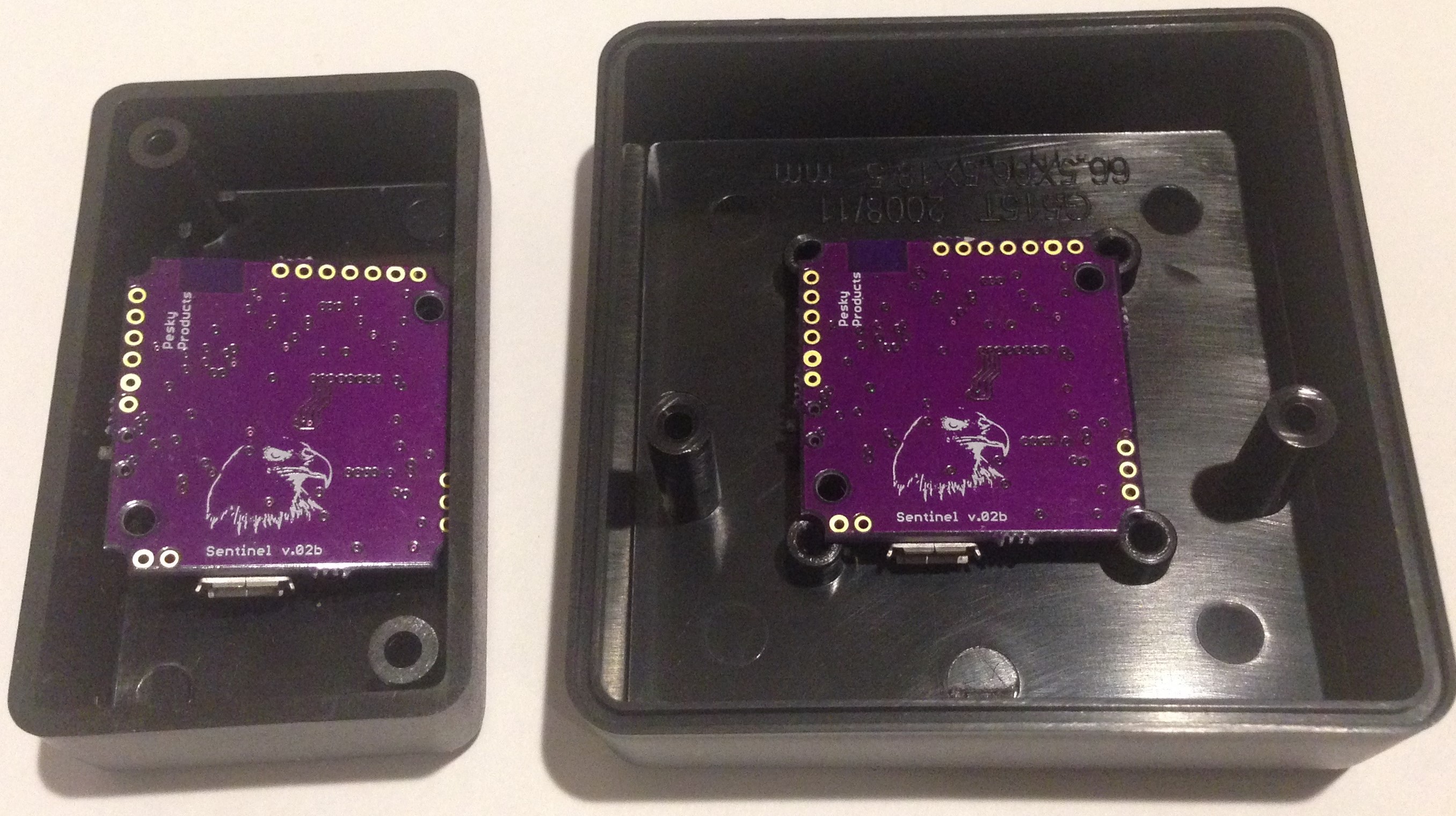
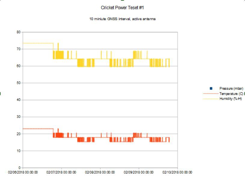
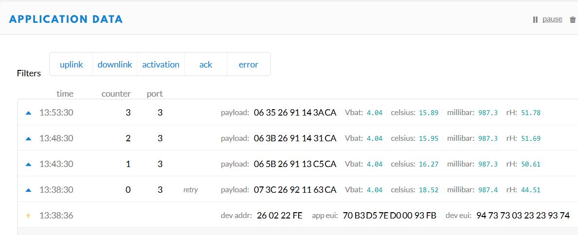
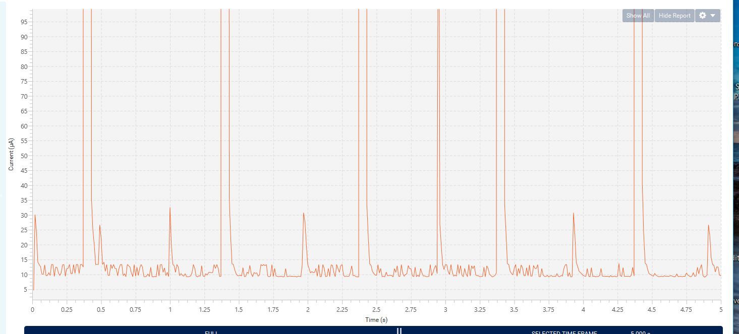
Lastly, the Cricket Asset Tracker adds a concurrent (GPS and GLONASS) CAM M8Q to the LoRaSensorTile component suite (no VEML6040 however) to allow asset location and asset tracking as well as motion and environmental sensing. The CAM M8Q can use its excellent chip antenna for lowest power or an external active antenna can be used for indoor use or use in difficult environments (urban canyons, construction sites, etc) at the cost of more power. Again, the components have been chosen for ultra-low power operation; Cricket has a sleep current of just 14 uA. By judicious use of the GNSS engine the Cricket is expected to last a year on a single AA battery.
We have developed a complete system layer for the CMWX1ZZABZ and an Arduino overlayer that makes using these devices very easy. Traditional tool chains can still be used for programming...
Read more »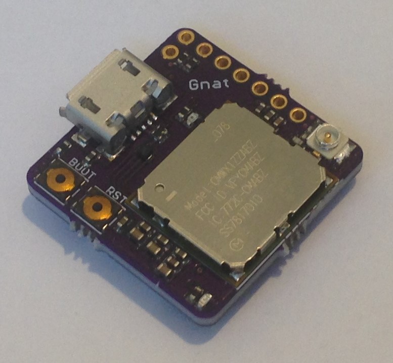


 Open Green Energy
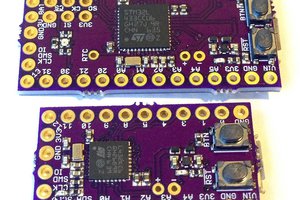
Hi,
Just wondering what is the recommended way to monitor the battery level?
I read that the Vin could be used as an output to read the voltage....is there config required to setup vin as an output?
Also, are there hardware mods I would need to do? My hardware knowledge is pretty limited.
Kind regards,Eamon