 icstation
ICStation team introduce you how to DIY this temperature & humidity & smoke alarm system based on ICStation Mega 2560 compatible with Arduino.The working voltage of this system is DC5V.It can measure the current temperature, humidity and smoke. It can display real-time data by the 1602 LCD and can realize the sound and light alarm when in the dangerous temperature and humidity. It is a simply and easily to operate monitoring alarm system about temperature humidity and smoke.
Functions
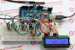
1.When connect to the power supply, after the initialization of hardware, the1602 LCDwill display the current temperature,humidity and smoke volume
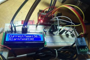
2.When we press the NO.1 key, the1602 LCD will turn the page and enter the dangerous temperature setting page.At this time, press NO.2 key once, the dangerous temperature will add one. If the actual temperature is higher than the setting value, the gree LED will light, at the same time the buzzer will alarm. When the actual temperature is lower than the dangerous temperature, the LED will go out and the buzzer will stop alarm.
3.When the 1602LCD display stays on the second page , we press the NO.1 key, you will see the 1602LCD will turn page to the third page and enter the dangerous humidity setting page.At this time, press the NO.3 key, the dangerous humidity will add one.If the actual humidity is higher than the setting value, the red LED will light,at the same time the buzzer alarms. When the actual humidity is lower than the dangerous humidity, the LED will go out and buzzer stop alarming.
Step 1: Components List
1.ICStation ATMEGA2560 Mega2560 R3 Board Compatible Arduino
2.DHT11 Digital Humidity Temperature Sensor
3.MQ-2 Gas Sensor Module Smoke Methane Butane Detection for Arduino
4.1602A HD44780 Character LCD Display Module LCM Blue Backlight
5.Active Buzzer Module for Arduino
6.830 Point Solderless PCB Bread Board MB-102 Test DIY
7.100K ohm 3296W Trim Pot Trimmer Potentiomete
8.1K ohm 1/4W 1% Accuracy Metal Film Resistor
12.Green LED 5mm DIP Hole Though
13.Red LED 5mm DIP Hole Though
14. 5 Voltage power supply
Step 2: Schematic Diagram![]()

Step 3: Hardware Wiring Program

Step 4: Introduce in power supply wire and GND wire

From ICStation Mega development board, introduce the 5V power supply and GND to the bread board. The red one as power supply wire and black one as the GND wire.
Step 5: Put in MQ-2 Gas Sensor Module

Connect MQ-2 Gas Sensor Module to the ICStation Mega development board,power supply and GND.
Step 6: Put in 1602 LCD

Plug in the LCD 1602 and potentiometer to the bread board and connect it to the power supply and GND
Step 7: Put in DHT11 temperature and temperature sensor

Plug in the DHT11 humidity and temperature sensor module to the bread board and connect to the ICStation Mega development board, power supply and GND
Step 8: Put in active buzzer module

Plug in the active buzzer module to the bread board and connect it to the ICStation Mega development board and power supply and GND
Step 9: Put in switches and resistor

Plug in the switch, resistor to the bread board and connect it to the ICStation Mega development board and GND
Step 10: Put in LED light emitting diode

Plug in the LED light emitting diode to the bread board and connect it to the ICStation Mega development board ,power supply and GND
Step 11: Provide Code and experimental effect
Code for your reference:
http://www.icstation.com/newsletter/eMarketing/alarm system code.txt
The experimental effect:
First, connect to the power supply,the LCD will display the first page of current temperature ,humidity and smoke volume.When we press the NO.1 key, the LCD will turn the page and enter the dangerous temperature setting page.At this time, press NO.2 key once, the dangerous temperature will add one.When we at the dangerous temperature setting page, we press the NO.1 key again, you will see the LCD will turn to the first page,at this time use your hand to touch DHT11 humidity and temperature sensor module,you can...
Read more »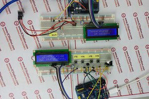
 Jasper Sikken