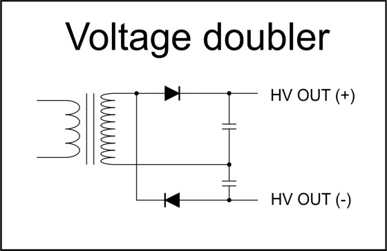
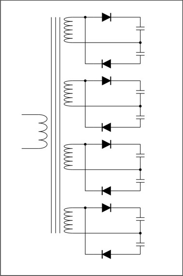
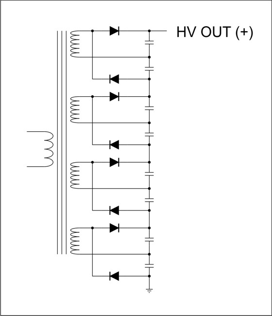
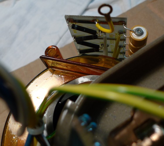
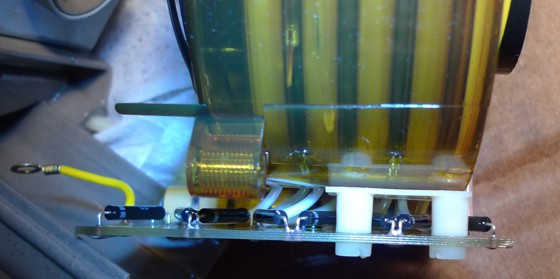
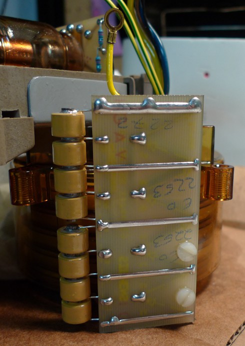
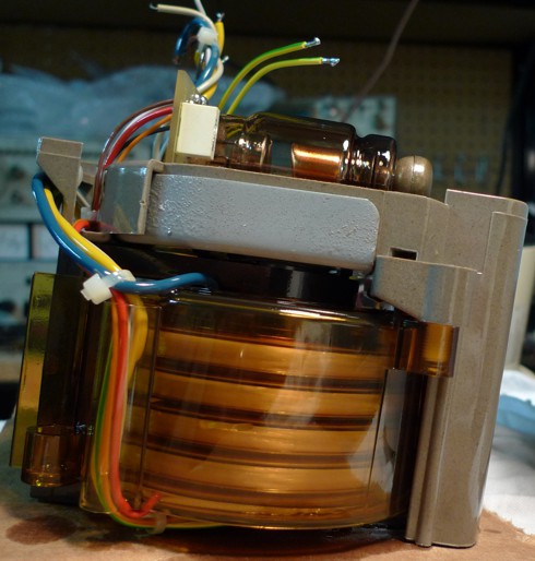
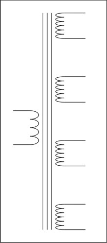
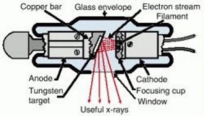
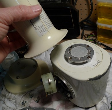
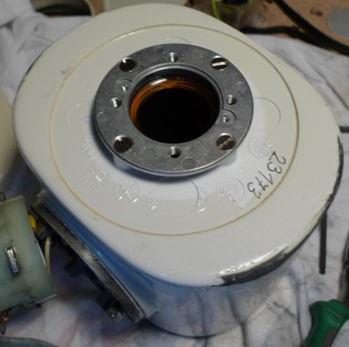
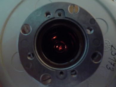
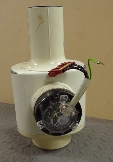
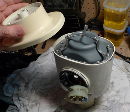
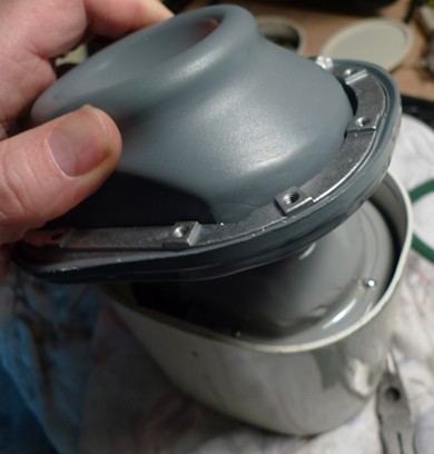
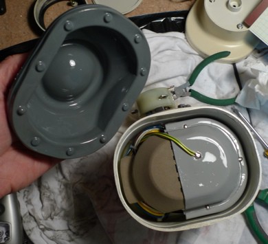
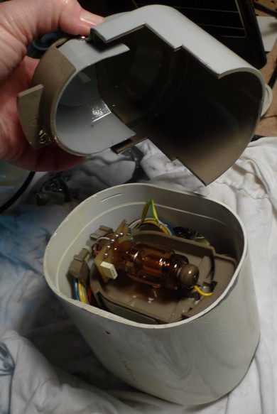
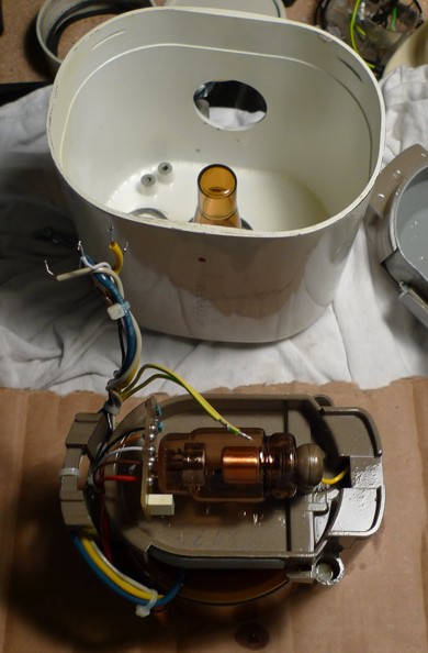
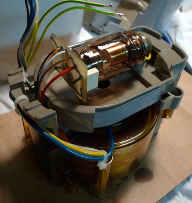
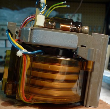
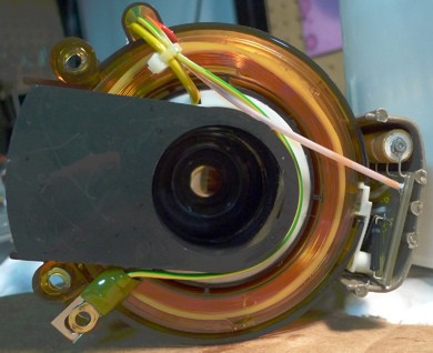
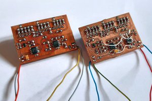
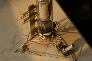
• High Voltage Circuit

    drhatch01/01/2015 at 06:25 0 comments

    This post will examine the high voltage output circuitry.

    Voltage Doubler

    The diode/capacitor circuit below is often used to double an AC voltage, while rectifying it to DC. (Note: Ignore the voltage increase from the transformer portion of the circuit. The voltage doubler is just the diode/capacitor portion of the circuit attached to the secondary.)

    This type of voltage doubler is frequently called a Cockcroft–Walton generator or multiplier.

    Imagine that this kind of voltage doubler were to be attached to each secondary winding in the xray transformer (see previous log entry) like this:

    This would generate four DC outputs, with each one electrically isolated.

    In the xray head the output of each voltage doubler is connected in series to create an output four times higher than each individual voltage. So the actual xray high-voltage circuit looks like this:

    The high voltage output is typically 70 keV, and it connects directly to the anode of the xray tube.

    The "ground" of the HV output is tied to the focusing ring of the xray tube, and is AC-coupled to the earth connection. (Full schematic to come...)

    I really like this HV output topology. Frequently, HV circuits have a single large secondary winding to generate a very high voltage, and then a single array of diodes and capacitors to double (or quadruple, etc...) the output.

    The arrangement reduces the high voltage stress by breaking it into lower-voltage, floating sections, and then stacks them to create the final HV output. Cool.

    In the picture below, you see the top of the PCB that holds the voltage doubler circuitry. The HV + output is the yellow wire.

    Below, you see the HV + on the left and the HV return (or HV -, or GND) on the right.

    Below is a picture of the back side of the HV doublers PCB. The HV + output is on the top.

    How to drive it?

    What type of waveform would you apply to the primary to drive this circuit? What frequency, what voltage, what current?

    I found someone who was selling this transformer online that said the transformer was meant to be driven by a 25 kHz square wave. This makes sense. The skin depth at 27 kHz is a large fraction of the diameter of 20 AWG wire, so going above 25 kHz reduces the current carrying capacity of the primary winding.

    I experimented by driving the primary with a low-voltage sine wave, just to see what kind of output levels I would find. At frequencies around 20 to 25 kHz, with a drive voltage of around 200 mV, the output was around 20 to 30 VDC out. I found that the HV output voltage dropped off significantly above 60 kHz.

    The 20 gauge wire of the primary should probably not be asked to carry more than around 10 to 15 amps.

    At the full 70 kV output, at the full 8 mA or so, means the output of the circuit is 560 watts. So the input power to the circuit (power to the primary) is probably going to be at around 700 watts.(!)

    So driving this circuit would probably require a half-bridge driver circuit, probably around 25 kHz, and probably using a supply voltage around 60 volts, maybe higher, at around 10 to 15 amps. Just a set of guesses.

  • The HV Transformer

    drhatch01/01/2015 at 04:58 0 comments

    This entry is to examine the transformer in more detail.

    Overview

    There are five windings visible, and these are the secondary windings. The top four are high voltage windings that will be connected in series. The winding on the bottom is a low-voltage secondary, and is probably used for monitoring the HV output voltage, although it might also be used to generate the xray tube's cathode current. More investigation is required.

    The primary winding (the yellow and blue wires) is wound underneath the secondary windings. Winding the secondaries directly on top of the primary is a common configuration.

    Ferrite Core

    As can be seen in prior photos, the core of the transformer is an open cylinder. So it seems like this is an "air core" transformer, but on closer inspection, it is seen that the core cylinder is lined with a layer of ferrite. That liner "flows" to the bottom, then to one side, and becomes a solid tube of ferrite that goes up to the top of the transformer (the dark tube on the left of the transformer in the picture above), where it goes back to the center (becoming a tube liner again).

    So the transformer is really like most transformers, in that it has a continuous core of a ferrous material. The core just happens to have a hole in it so the xray beam can flow unobstructed through the middle of the transformer (from top to bottom in the picture).

    QUICK TANGENT ON "AIR GAPS"

    This transformer is meant to be operated as a flyback transformer (a transformer operated in discontinuous mode), which means that energy is built up over time, and stored, in the magnetic field, and then periodically and quickly discharged into the secondary.

    Ideal (and practical) magnetic materials store very little magnetic energy. In order to store and return energy to the circuit efficiently, a small gap is required.

    This air gap increases the magnetic leakage (flux that does not couple the primary and secondary), and therefore also increases the inductance of the primary.

    This transformer is no different. The gap is at the top of the cylinder lining portion of the ferrite core.

    The Primary

    The primary is wound with 20 AWG solid wire, with varnish insulation.

    I measured the primary DC resistance at 0.13 ohms. With 20 AWG wire, this equates to a length of 150 inches of wire. The leads were each 9" long, so the core is wound with 132" of wire.

    The core diameter is 2", so this means the primary has 21 turns.

    Note: I have not dismantled the core, so I am assuming the primary windings are of the same wire type as the primary lead wires themselves. If the windings have more copper, it is possible there are more than 21 winds on it.

    The Secondaries

    There are four high voltage windings on the secondary. These are wound with many turns, using thin wire.

    There is also another secondary, wound with thicker wire and fewer turns. For now, I will not focus on this winding, other than to say that one of the wires to this winding is labled "HV." The second wire for this winding is tied to the earth wire. This secondary winding is probably used to indirectly monitor the HV output of the transformer.

    So here is a simple schematic of the primary and the four HV secondary windings:

    In the next post, I will discuss how the high voltage DC output is created using the transformer and voltage doublers.

  • Input connector pinout, cathode glow

    drhatch12/22/2014 at 23:57 0 comments

    As mentioned in a previous log, the input connector is a 6-pin molex plus an earthing wire (ground wire).

    A key objective is to define the pinout of the connector of the xray head.

    To help figure out the function for each pin, it is useful to have some idea of what the xray head needs.

    Let's start with the xray tube itself. It is a simple device, with only four pins.

    Inside the xray tube there is a heater filament (the cathode). The function of the cathode is to boil off electrons that will be accelerated toward the anode. So we can expect that the input connector will have two pins that connect to the xray tube's cathode.

    Near the cathode is a focusing cup. This is often set to ground (return for the cathode current) but I was thinking perhaps it would be accessible via the main connector.

    The other part of an xray tube is the anode. This is the target for the electrons. The anode is held at a very high voltage, around 70kVDC. This is created by an internal high-voltage transformer, so we can expect that there will be two pins, maybe three, that connect to the primary of the high voltage transformer.

    Also available via the connector could be a feedback pin to monitor the high voltage output. That pin would provide information about the high voltage but at a lower voltage or current (or both).

    CONNECTOR PINOUT

    After disassembling the head as discussed in the previous post, I determined the pinout to be:

    Pins 1 and 2: Primary of the HV transformer.

    Pins 3 and 4: Cathode of the xray tube.

    Pin 5: Connects through a series 30K resistor to the focusing cup.

    Pin 6: After opening the unit and examining the HV transformer, I found an isolated secondary winding. One side of that winding connects to this pin. The other side of this winding connects to Pin 4 (cathode return). I believe that this winding will output a voltage proportionate to the output of the high voltage windings. Further experimentation is needed.

    MAKING THE CATHODE GLOW

    I thought it would be nice to make the cathode glow. If for no other reason, it would verify that the heater in the tube in this unit is functional.

    To do this, and prior to fully disassembling the unit as described in my previous post, I opened up the front of the case to have visual access to the tube.

    I applied a low voltage (~1 VDC) to the cathode pins, 3 and 4, and looked for the glow of the filament.

    Success.

    I then sealed up the front, and went back to disassembling the unit from the back, as discussed in the previous post.

  • Opening the Case

    drhatch12/22/2014 at 22:34 0 comments

    The first thing to notice about the head is:

    1) The 6-pin molex connector plus earthing wire.

    2) The long tube, which is where the xray beam comes out of the head.

    3) The aluminum plate at the base of that tube. It filters the xray spectrum. More on that in future posts.

    Opening the case was the first step. I know that these cases are full of insulating oil, so I had to be prepared for draining the oil prior to further disassembly.

    I opened the case through the electrical port, drained a bit of oil using a "turkey baster" type of syringe, drained some oil, then tipped the case to finish extracting the oil.

    NOTE: I do not know what kind of oil it is, nor if there are any hazardous additives, so I treated it very carefully, cleaned carefully, and stored the oil in sealed containers. There was a total of 1 liter of oil.

    After draining the oil, the next step is to access to the internal components from the "back end" of the chassis.

    Now were are getting somewhere!

    There is an earthing wire soldered, so I un-soldered that. NOTE: the wire is soldered to a soft lead sheet piece that (along with the steel chassis) shields the outside environment from xrays.

    After lifting the shield assembly out, we see the xray tube.

    The half-cup of light gray on the left of the shield (that I am lifting off in the photo below) is 1.0 mm thick. The half-cup of light gray on the right of that part is 0.7 mm thick.

    It is interesting that the shield closest to the tube is thicker than the piece that is only slightly further away (1.0 mm versus 0.7 mm).

    After removing three screws holding the tube/transformer assembly into the case, it lifts out.

    Now that I have full access to the internal components, I can begin the investigation and analysis.

    One early discovery/surprise is that the xray tube is located at the rear of the unit and fires toward the transformer. I more-or-less expected that the tube would be at the front of the unit (toward the output cylinder) with the HV transformer behind the tube, not the other way around.

    This is possible because the transformer has a hollow core tube, and that tube is lined with (probably) ferrite.

    This means that the transformer, besides creating the high voltage, is also acting as a beam collimator, narrowing the output beam by blocking the outside portion of the xray cone.

    In the next posts, I will explore the components and conduct some experiments to characterize them.