 deʃhipu
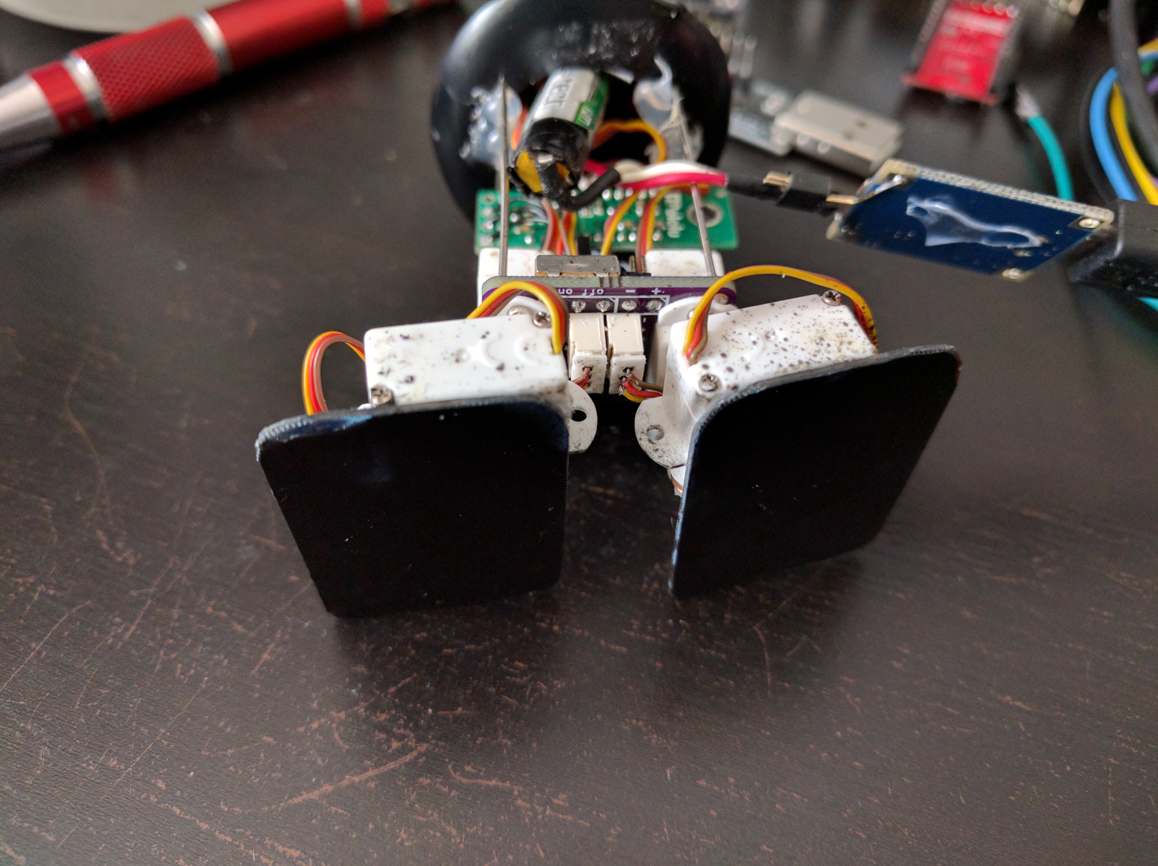
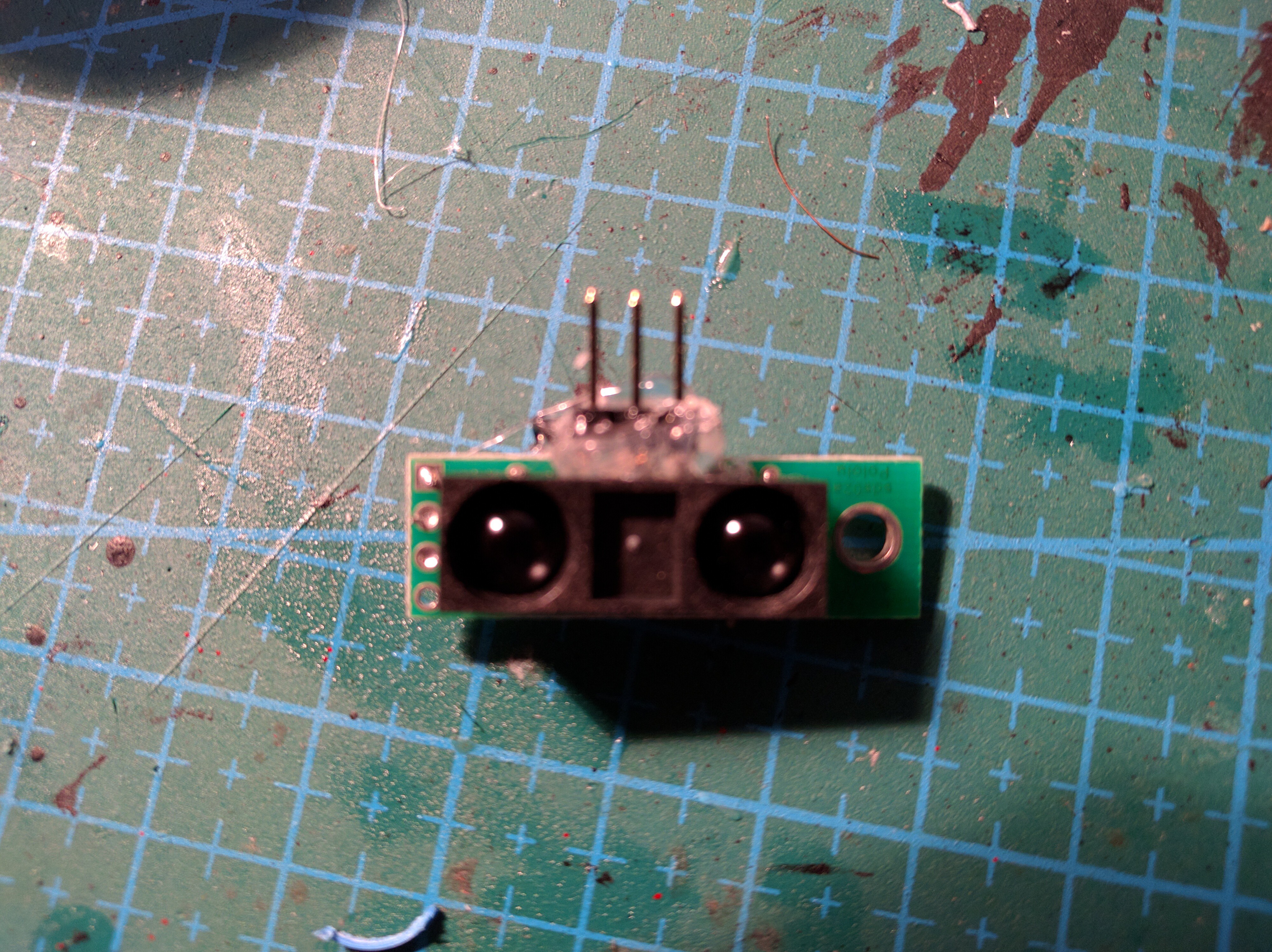
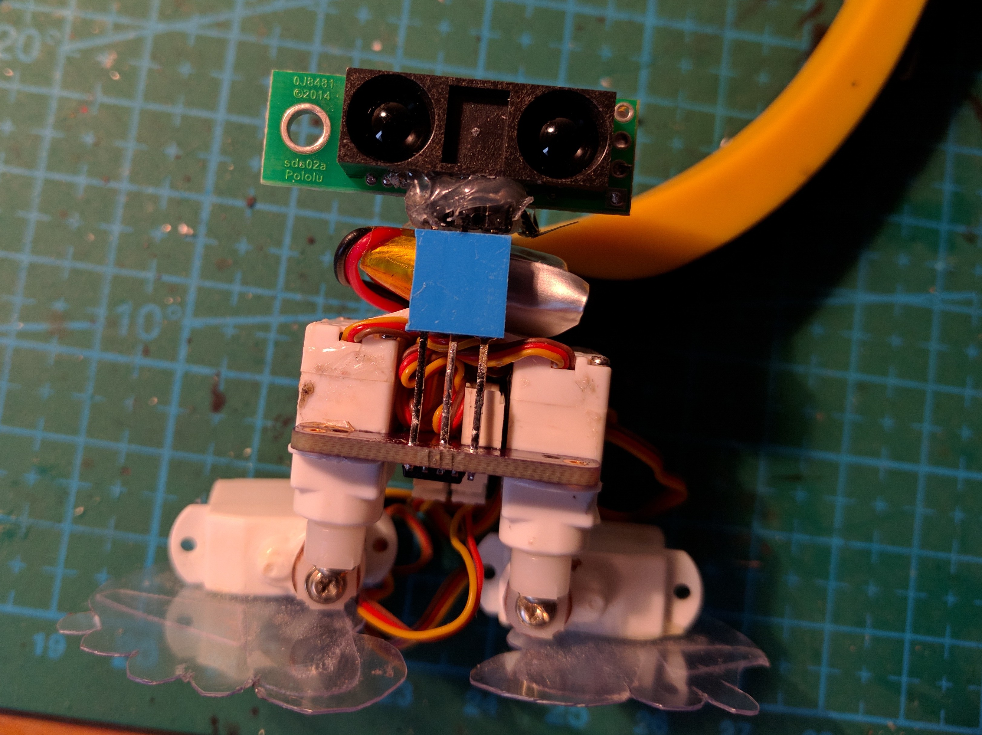
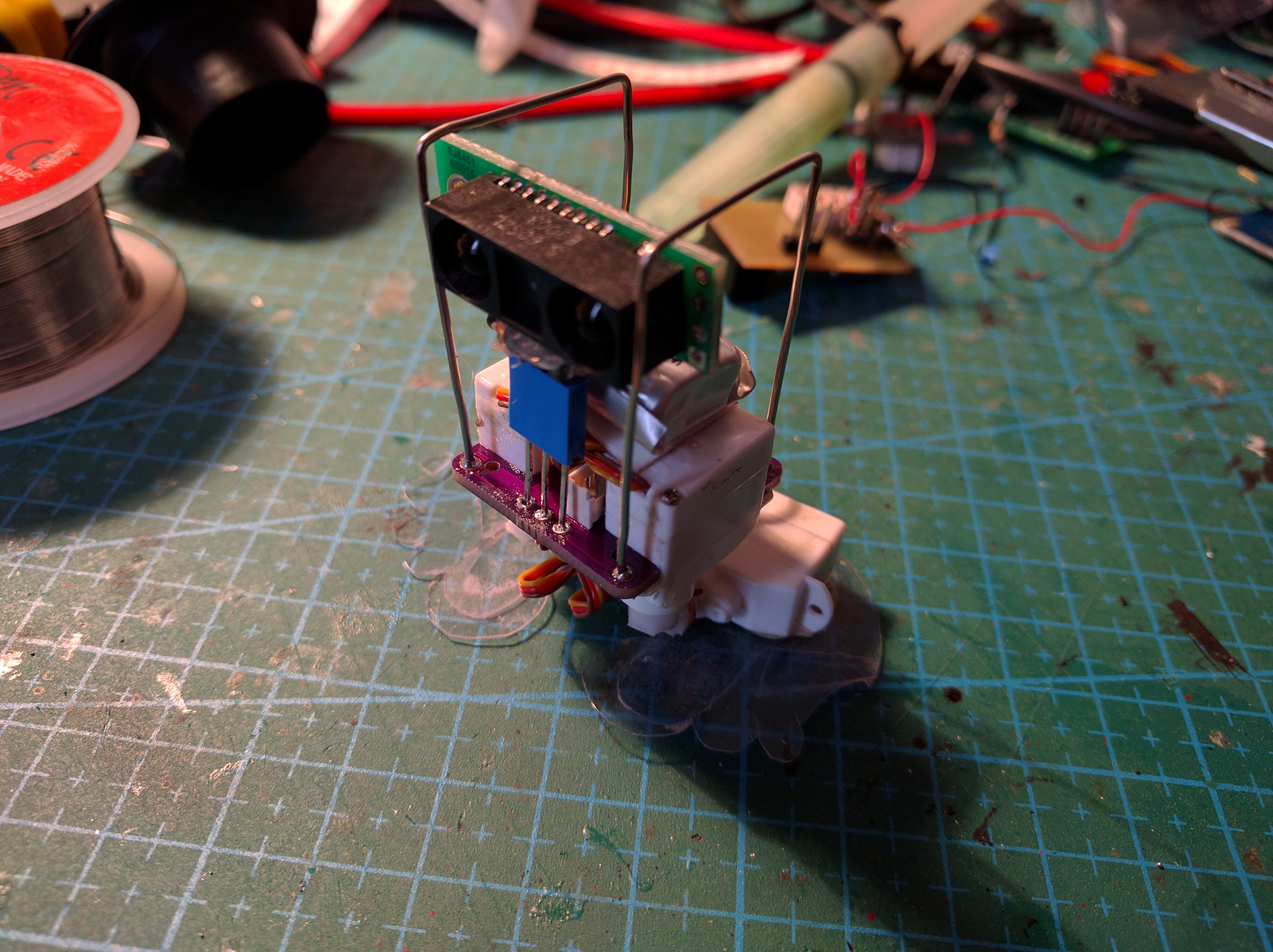
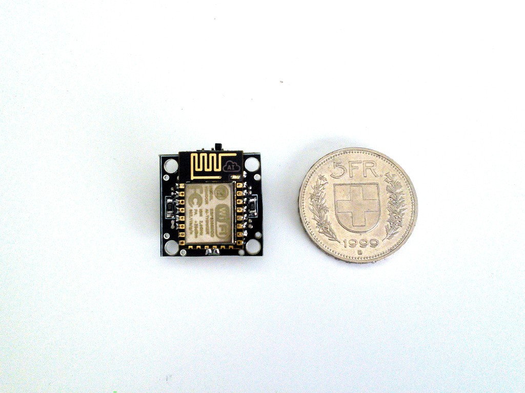
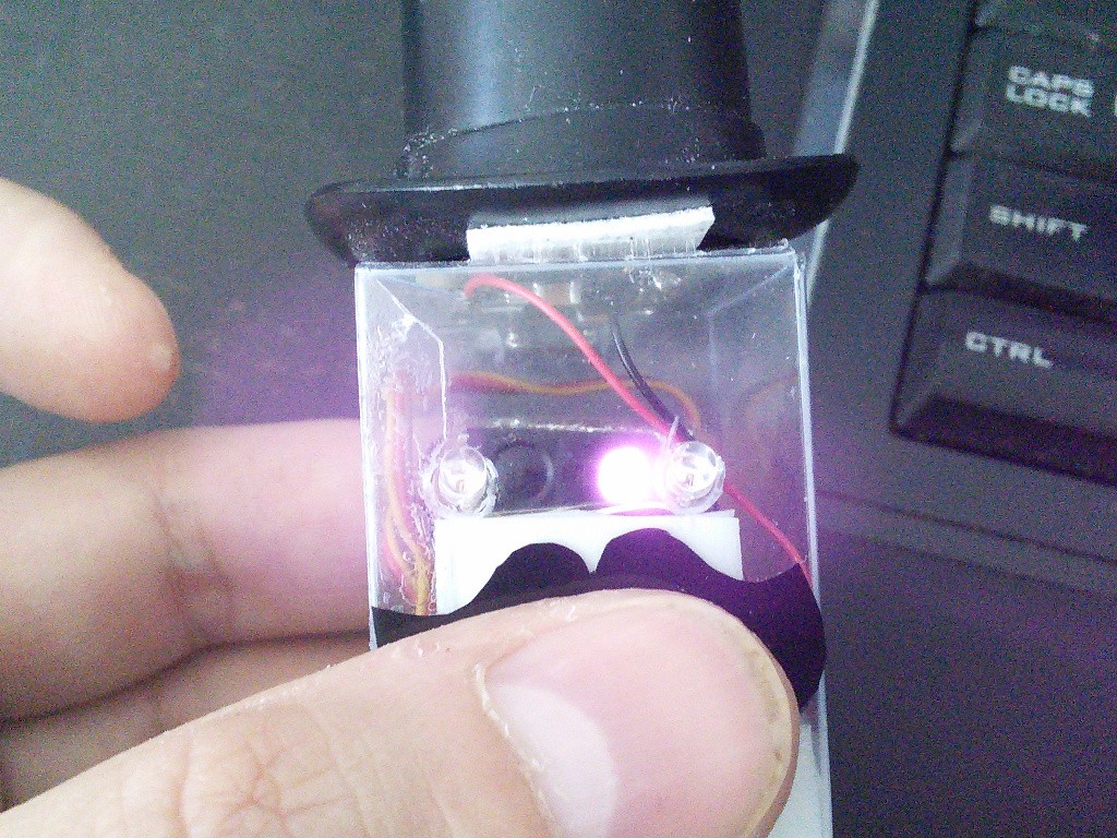
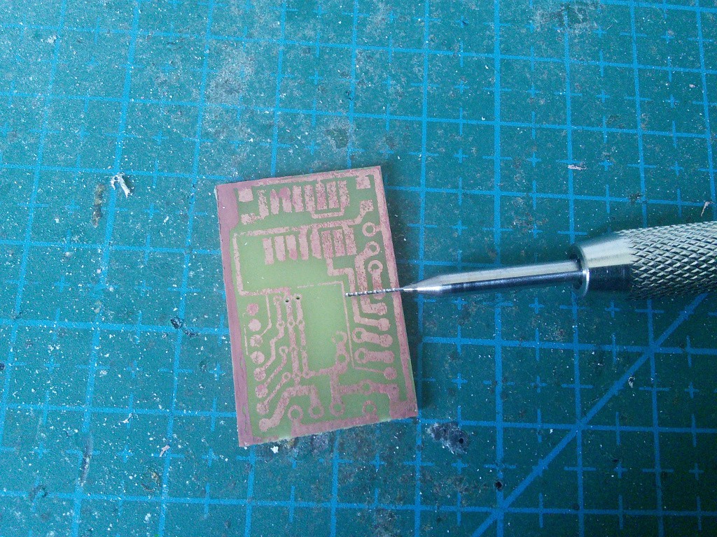
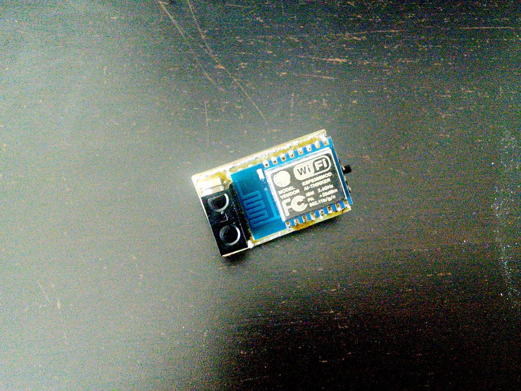
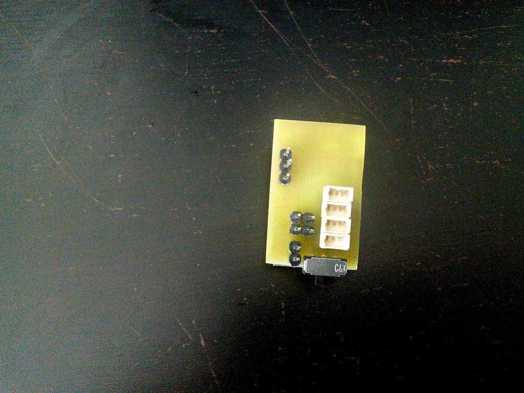
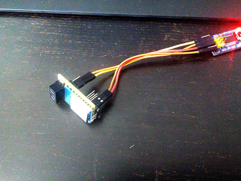
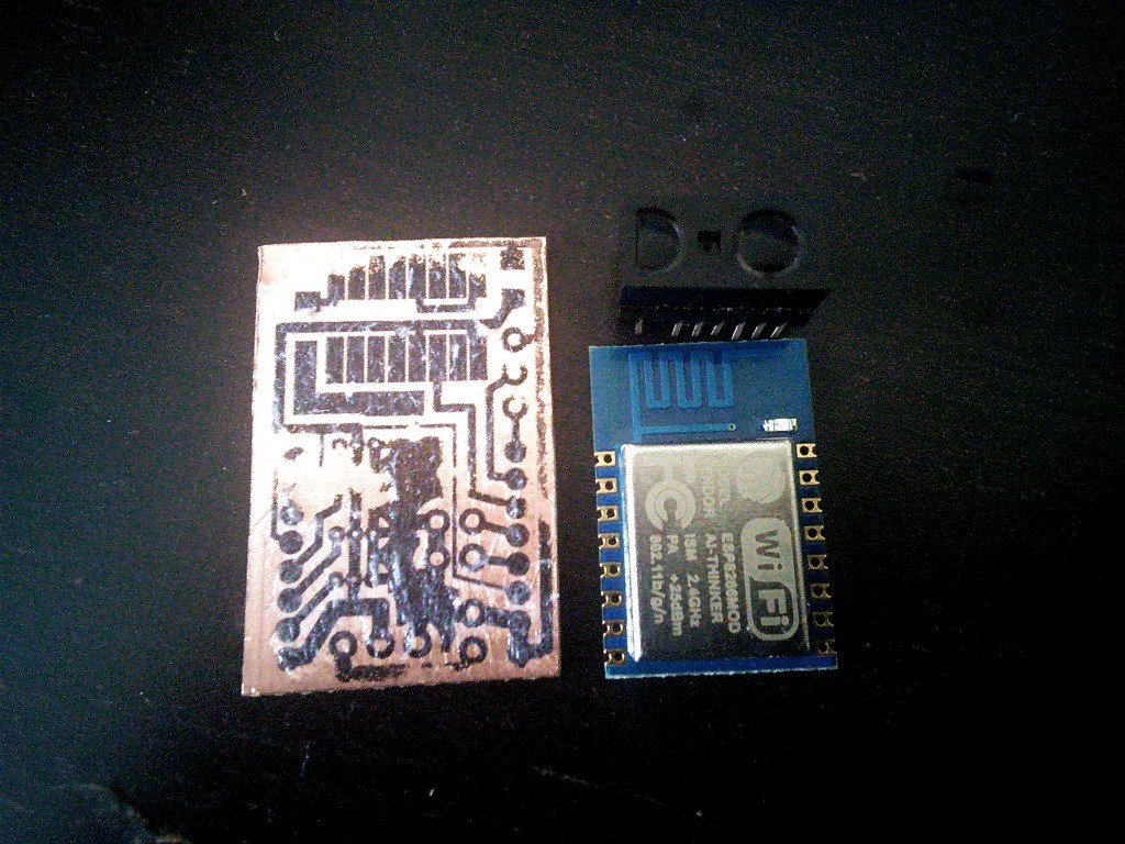
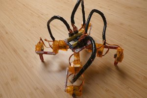
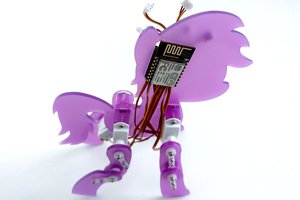
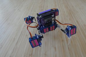
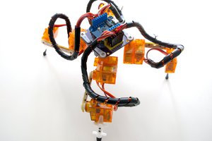
This is a tiny, minimalist version of a popular biped robot design. I used tiny hobby servos, a very small lipo battery, a SHARP distance sensor and an ATtiny85 (previous version used an ESP8266 module).
0%
0%
µBob biped robot
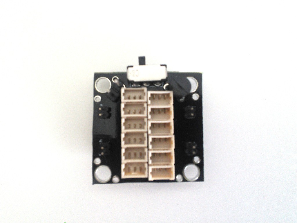
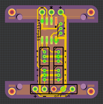
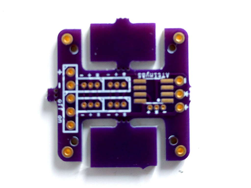
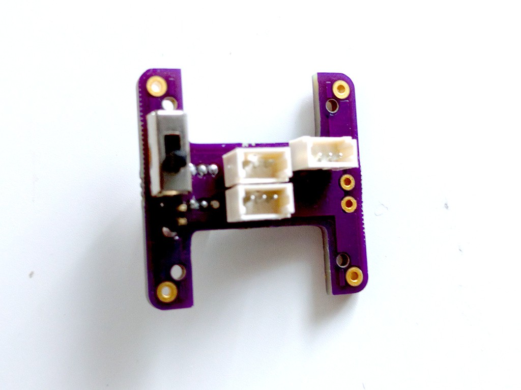
Two legs, four servos, ATtiny85 for brains
Become a Hackaday.io member
Already have an account? Log in.
Just one more thing
To make the experience fit your profile, pick a username and tell us what interests you.
Pick an awesome username
hackaday.io/
Your profile's URL: hackaday.io/username. Max 25 alphanumeric characters.
Pick a few interests
Projects that share your interests
People that share your interests


Awesome i love Bipeds, interesting to see new ways of programming them, would be cool if the hat can add some festure