 Owen Trueblood
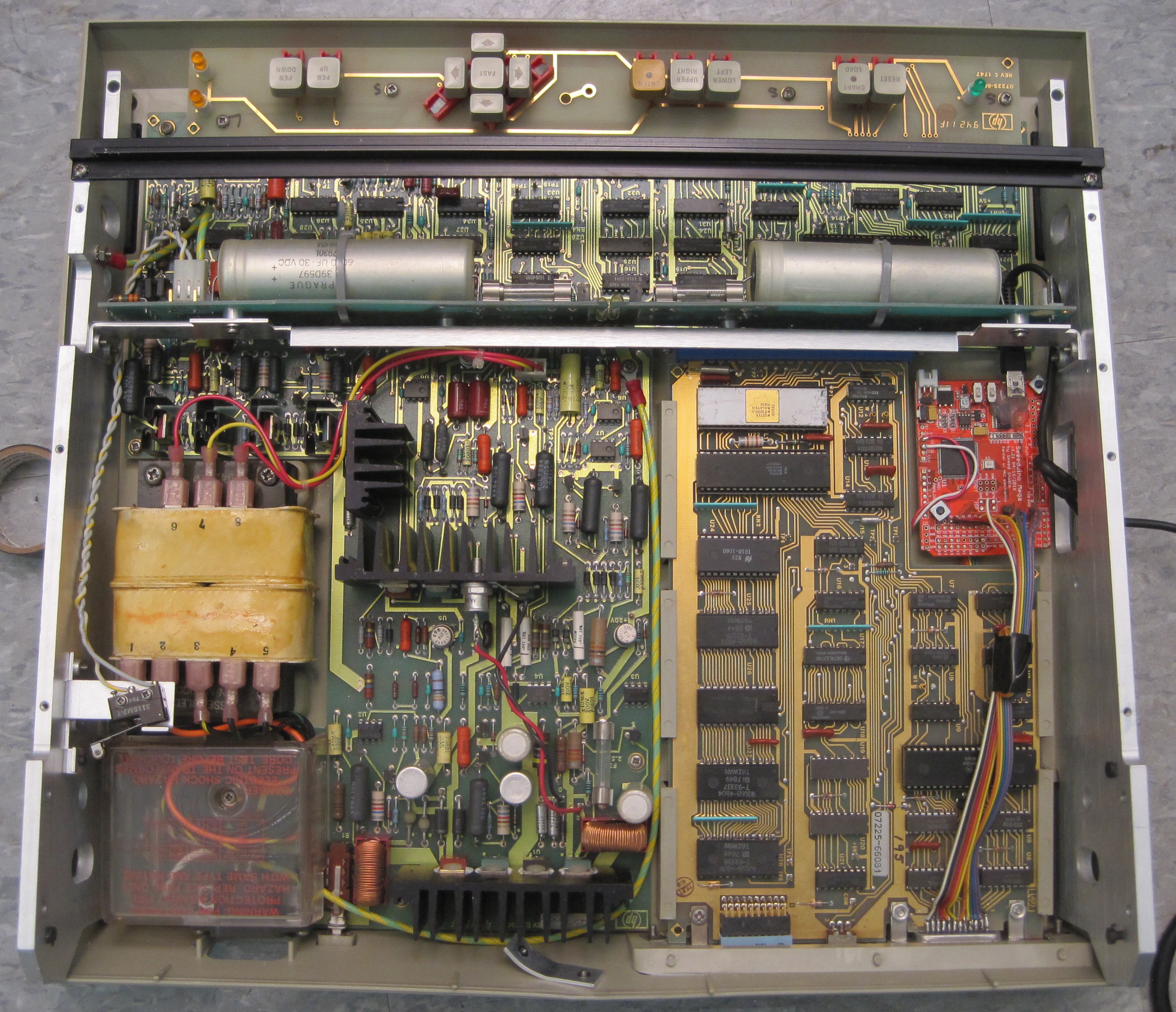
Analysis
Before making any modifications I took some time to understand how the plotter works. It is a nicely designed old machine that would have run you more than $1000 if you had bought it when it was new - in the 70s. There is a bunch of 7400 series logic on two of the four big PCBs to run the show. In the lower left is all of the power management. Most of the system uses 5 volts, but the vertically oriented board uses a higher voltage.
The logic near the buttons handles the driving and positioning of the two stepper motors that move the pen head and drives the solenoid that lowers the pen. The buttons get their own board without any logic. It connects to the "motherboard" using a spring contact connector. The pretty removable card (17601A "personality" card) in the lower right is where most of the intelligence is located. The white chip is an F8 family CPUdesigned by Fairchild and manufactured by Mostek. The other chips include a memory interface, an EPROM, some 7400 series logic, and an interesting "general purpose interface adapter" chip (MC68488) that exposes IEEE-488 compatible communications via an M6800 compatible interface.
The vertically oriented board with the two giant capacitors (1F at 30 volts each) is pretty interesting and unique. It is used to generate a static charge on the plotter's surface so that paper is electrostatically pulled flat. It is a really cool feature that I have no need for in Metron. Maybe I can figure out how to extract it for use in another project. Unfortunately the board combines that circuitry with the plotter head connectors, so I cannot just pull it out.
Modification for Control
After looking up information about the plotter and its circuitry online I knew that in its original use it would have been controlled by a computer with an IEEE-488 compatible bus. There are other easier ways to control the plotter (like RS-232), selected by swapping out the "personality card", but unfortunately I got a plotter with an IEEE-488 card. Thankfully, after a tiny bit of Google searching I found the neat agipibi project by Github user tibal. It lets an Arduino Mega serve as a translator between a PC and an IEEE-488 compatible bus (GPIB).
Luckily I had a Seeeduino Mega kicking around in my parts bin from an old project. And serendipitously it fit perfectly into an space inside the plotter next to the interface card (space left for ventilation, it seems). All I had to do was solder a bunch of wires between the GPIB connector and the Arduino, find 5V and ground, bolt the Arduino down, and route a USB cable out of the ventilation screen in the side of the plotter.
It took a little tweaking of the Python code to get a connection up because electrical noise causes the Arduino to reset several times before a successful connection is made, but after that everything worked as advertised. I can now send HP Graphics Language (HPGL) commands to the plotter and see it do my bidding.
Discussions
Become a Hackaday.io Member
Create an account to leave a comment. Already have an account? Log In.