Close
0%
0%

Odroid XU4 based Control Computer

The goal is to create an all-in-one control system capable of running algorithms of moderate complexity with sensors and outputs built in

Similar projects worth following
This project started spring of 2017, and I have finally felt I have made enough progress to publish what I have been doing here on Hackaday. This project started while I was taking a Bayesian Robotics course, and I thought it would be interesting to apply what I have learned. The only issue was there was no embedded Linux system for a reasonable cost that had the computing power to run large particle filters, that also had the required sensors (GPS, IMU) of a reasonable quality built in. So I decided to make one.

Design Specification

Sensors

  1. The board will host multiple MEMS IMU on different buses, for redundancy and to allow the implementation of a multiple sensor Bayesian filter.
  2. The board will host a single GNSS reciever to allow localization accuracy of +-2.5m when outdoors. GNSS was picked for access to both US GPS and Russian GLONASS systems, and a quicker cold start time.
  3. The board will support an analog front end capable of measuring voltages up to 20V for battery voltage monitor.
  4. The board will support an analog front end capable of scaling a -5V to 5V signal to 0 to 1.8V.

Communication 

  1. The board will host a XBee Pro module

Actuation

  1. The board will support direct PWM outputs for control of external devices.
  2. The board shall not provide power for these external devices.

Part Selection

IMUs (Version 1)

BNO055 was selected for two of the IMUs, mainly due to its use in Pixhawk controllers. LSM9DS1 was selected as the third sensor, for redundancy, a different I2C address, and because it looked interesting.

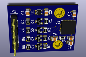
Version 1 is the currently completed PCB show in the photos above. Version 4 is the next version of the board that is currently under work.

Sensors (Version 4)

BNO055 leaves some things to be desired, and electrical noise from the rest of the system causes noise on the magnetometer, so the BNO080 will be used instead. It is approximately 3x more accurate, due to the superior fusion algorithm used onboard. It also provides an estimate of how accurate the data it provides is, which is important for the gps/imu filter I am working on. It also support an external barometric pressure sensor.

5.2mm x 3.8mm x 1.1mm
Up to 1KHz
2.0msec
3.0° - Dynamic 1.0° - Static
0.5°/min
± 2000°/sec 

BHI160 will also be used as the second IMU, and the sensors are comparable in accuracy to the BNO080, the resulting sensor fusion is not as good. However, this IMU does support an external I2C magnetometer sensor, which I will design a carrier board for and remote away from sources of electrical noise. This will allow me to accurately determine magnetic north.

BMM150 is the external magnetometer, which is supported as a direct input into the fusion algorithm in the BHI160. It actually quite nice as sensor go, although it is a bga, which will be fun to reflow.

Logic Level Conversion

The XU4 IO voltage is 1.8V, and thus logic level conversion is needed. The TXB0108-PW was selected due to OEM recommendation.

GNSS

A5100-A was selected from Maestro Wireless Solutions since it is a GNSS capable receiver, with active antenna support. It is an all in one module with minimal external components.

Schematics (Version 4)

Magnetometer carrier board

Sensor Board top level schematic, with odroid xu4 connections, logic conversion, on-off button, and i2c to differential i2c conversion and RJ45 connector.

Sensors

Power

Analog front end, converts a 8V to 13.8V  and -5V to 5V signal  to 0V to 1.8V to be fed into the odroid xu4.

I2C controlled LED driver (outputs programmable PWM signals, 16 channels)

Xbee Serial communication link

Board Layout (Version 4)

4 layer board with a segmented 3.3V 1.8V power plane and a GND power plane.


  • General State of the Project and Updates

    williamg4206/10/2019 at 14:03 0 comments

    Sorry for the complete lack of activity, unfortunately graduate course work got in the way of really working on stuff for fun/this project took a back burner to some other projects. 

    Revision 5:

    So the Revision 5 PCB was built and tested (I'll add some photos when I get a second/find where I  stuck that PCB) and found it non functional. Oh the BNO080 showed up on the I2C bus, but I could not get any data out of it. No matter what code I tried or how I probed the buses, I could not get data out of the BN080. 

    After a year, it still appears that no one has a working BNO080 driver for a linux computer. The closest I found was this wonderful code writing by fm4dd: https://github.com/fm4dd/pi-bno080 which was able to talk to the BNO080, but was not able get any position or acceleration data. So the Revision 4 PCB is the final, working version I will possible be moving forward with. 

    IMU GPS Fusion Algorithm

    One of the things I did play with was a GPS IMU sensor fusion algorithm using particle filters and a loosely coupled IMU/GPS. The code is here: https://github.com/williamg42/IMU-GPS-Fusion and hopefully someone could find it useful. The big issue was how noisy the BNO055 was and my inability to directly impact its sensor fusion parameters. It did work, but not at the level I was hoping for. This lead to the Version 5 PCB where I wanted to use the improved performance of the BNO080 to reduce overhead on the odroid xu4 (so it didn't have to run a particle filter and IMU sensor fusion) and hopefully create a more accurate GPS IMU sensor fusion.  


    Box doesn't fit in robot

    So the plan for this system, and its fancy box, was to be the controller for the ruggedized robot platform project. Except I didn't measure, and the whole box system I built is too big to fit in the platform. (Remember, measure twice cut once!)

    Lack of a true UI

    Finally, the last issue that kind of caused a stagnation of this whole project (both the control computer and the ruggedized robot) was the lack of any way I could come up with for a user to control and interact with the platform. While ground control station software does exist, its intended for MAVLink, which is a somewhat confusing protocol, and working with the ardupilot project. Porting the ardupilot project over faced some huge issues, especially with how much great work that team has done with real time scheduling and other optimizations. While hardcoding GPS waypoints in was possible, it just didn't seem worthwhile. 

    The Future

    Now that the BNO080 path is abandoned, I have a fully function board and odroid xu4 combination sitting on my desk. Granted the new odroid N2 board that was recently released in more powerful, tolerant of 3.3V, and uses a standard 2.54mm 30 pin header means a lot of the complexity (and funky headers) of this project is no longer needed or desired. 

    In addition, thanks to the Onion Omega2 project I have a basic UI platform that seems to work well, and is easily expandable for new features and is completely platform agnostic. (After I defend my thesis I'll be putting up a write up for the three spin off projects that project generated)

View project log

Enjoy this project?

Share

Discussions

Similar Projects

Does this project spark your interest?

Become a member to follow this project and never miss any updates