 danielmiester
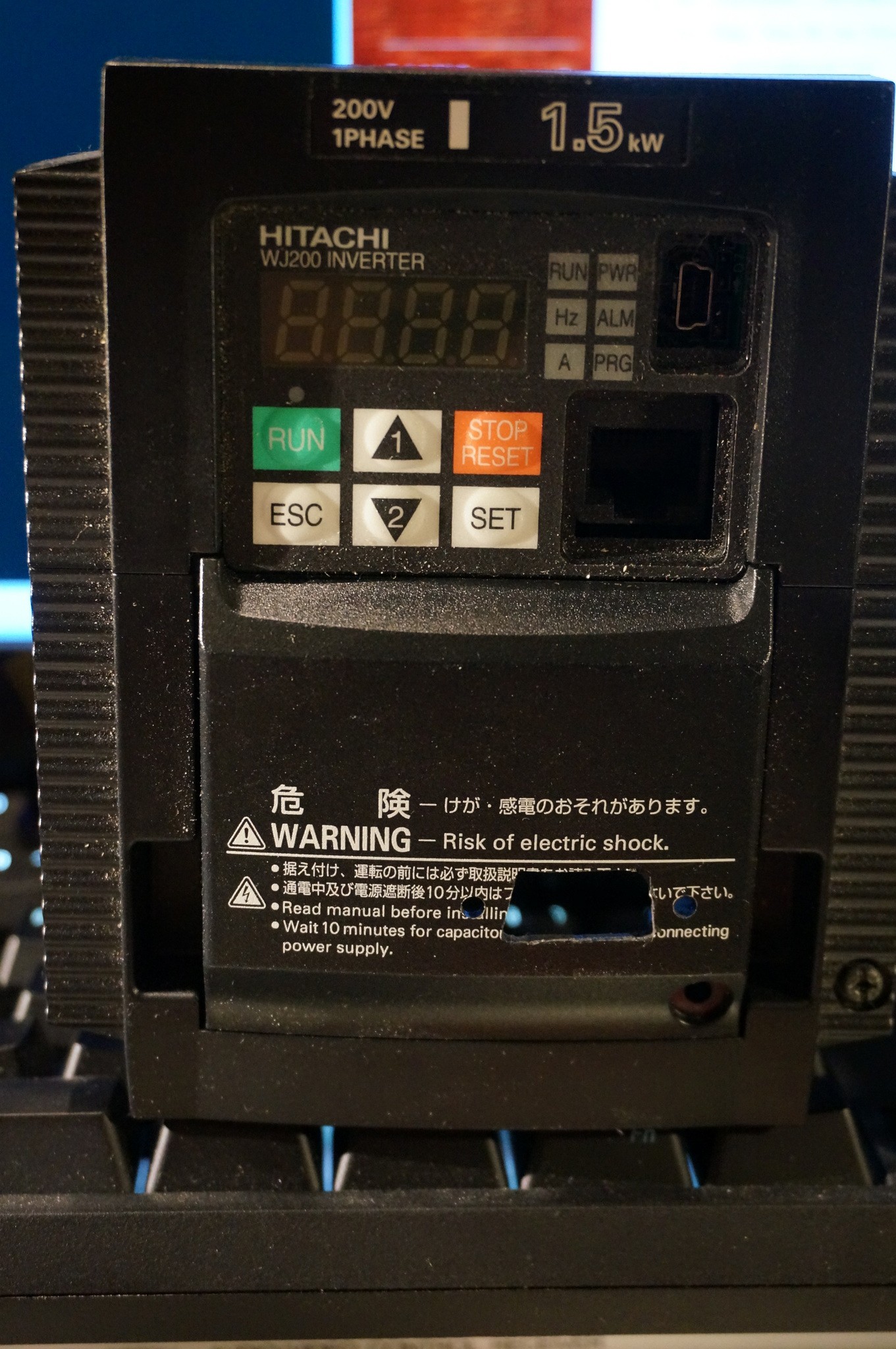
I originally got this motor controller because I was trying to create a frequency converter for another project. I figured it was essentially 3 half bridges tied to a common DC bus that were PWM'd to create a pseudo 3 phase AC output. I picked it up on ebay NIB for something like $120USD
Here's the very basic 10k foot view of these units.
Except in my case, there wasn't a 3phase input rectification, it was only a single phase bridge rectifier (just mentally remove one of the vertical diode chains on the left)
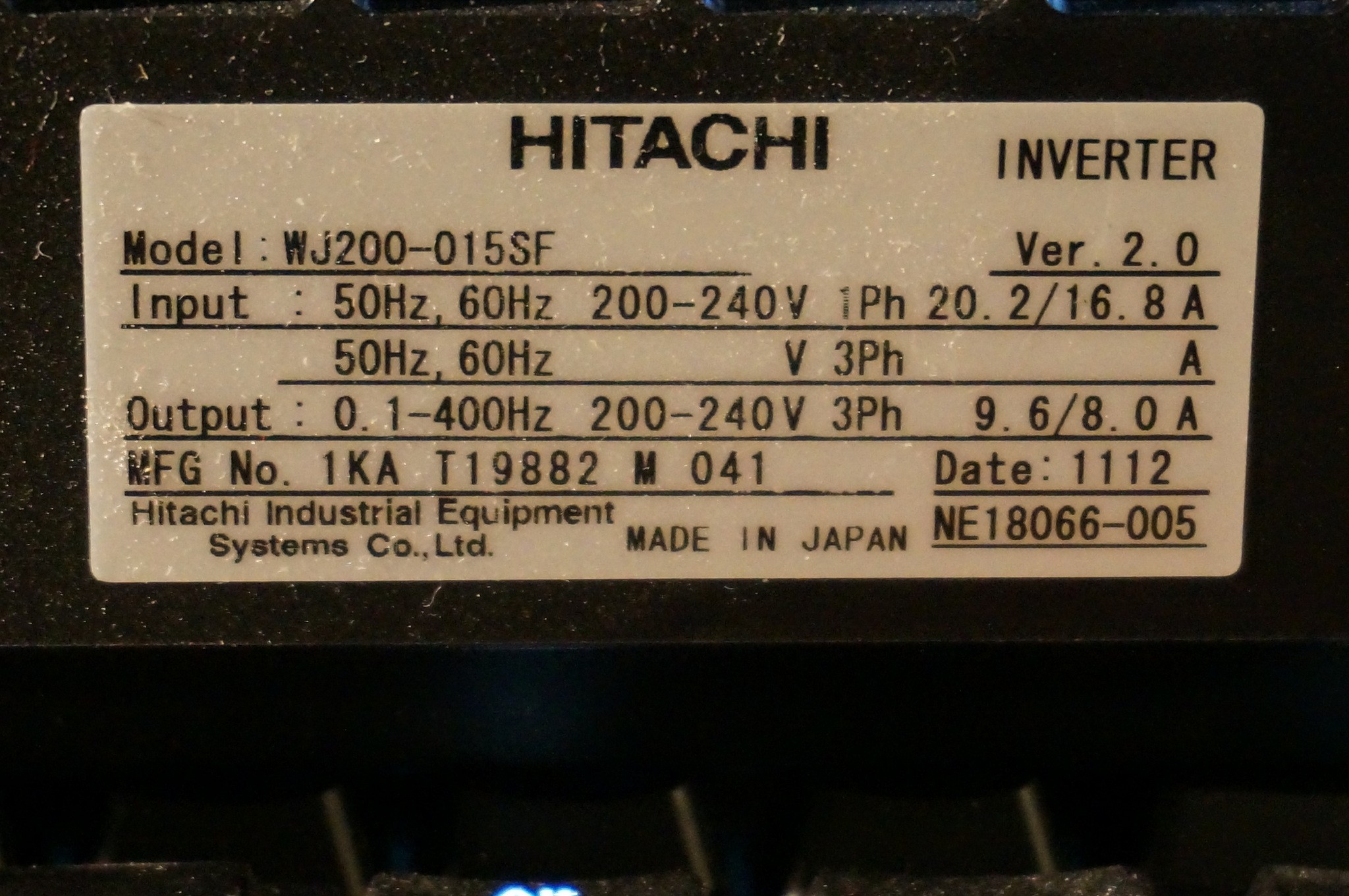 Here's the nameplate in case you're curious
I opened it up and discovered that it had a weird switchmode supply tied into the DC bus. that fed through a couple of hard soldered interconnect headers. I had to cut them apart to get the unit apart.
This is where I left the unit for almost a year.
In pieces.
On my desk.
Just dying to have pieces lost for all eternity (or at least until the next major cleanup)
Until Christmas. I got almost 2 weeks off from work for the holiday, and I thought I may as well start exploring it again, and at least reassemble it.
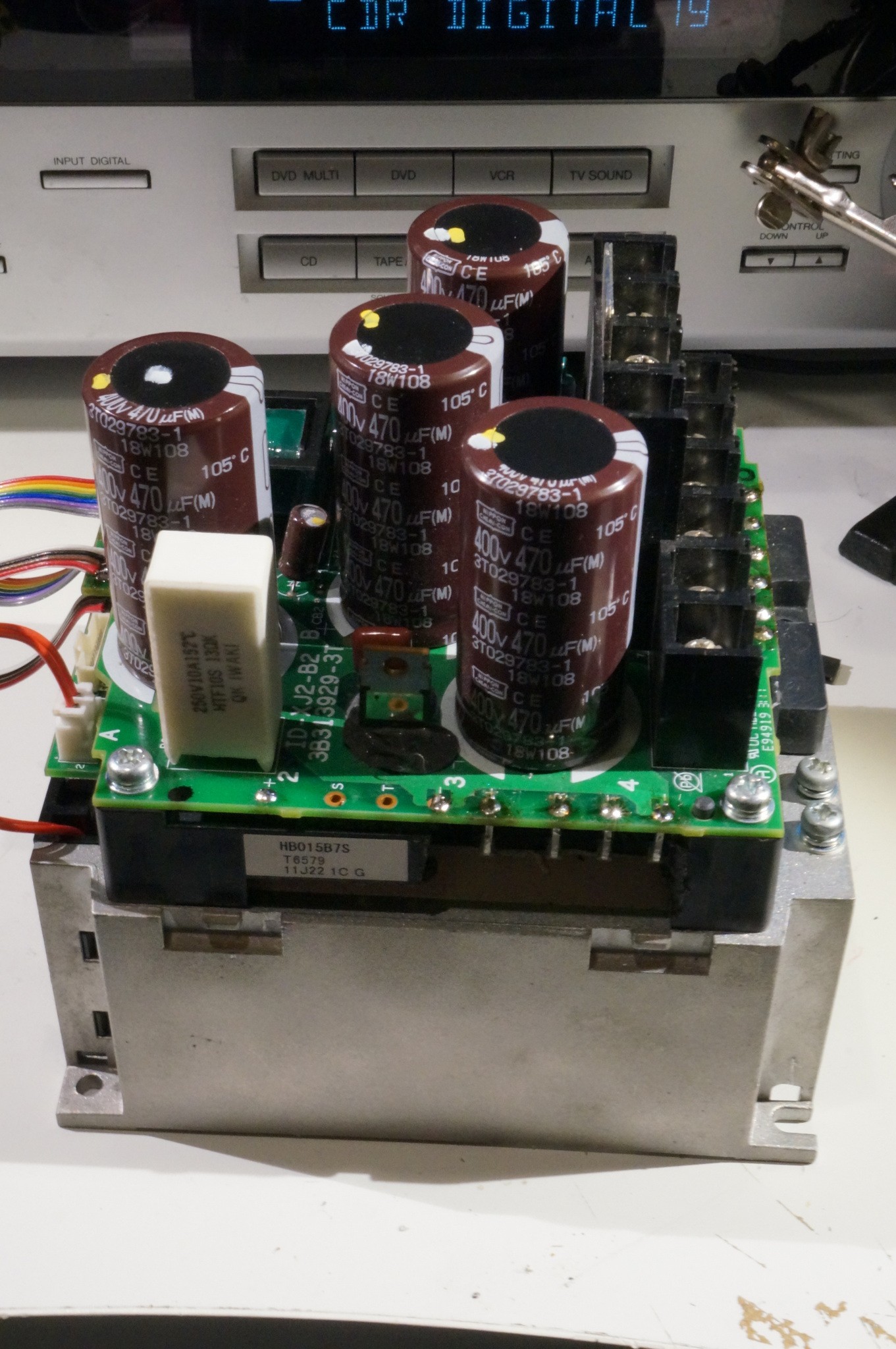
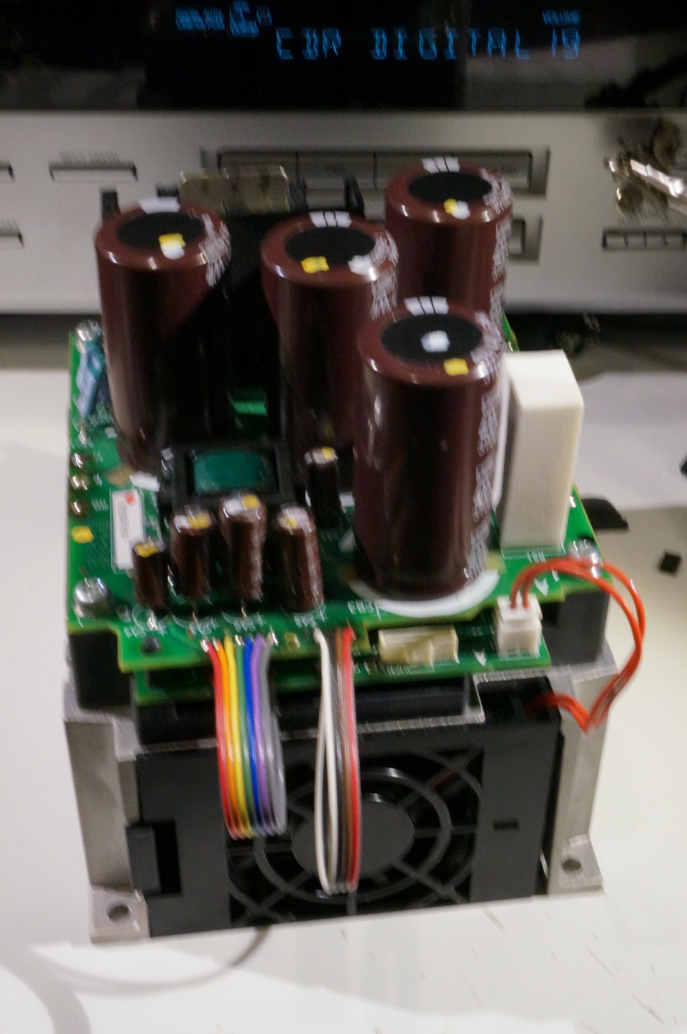
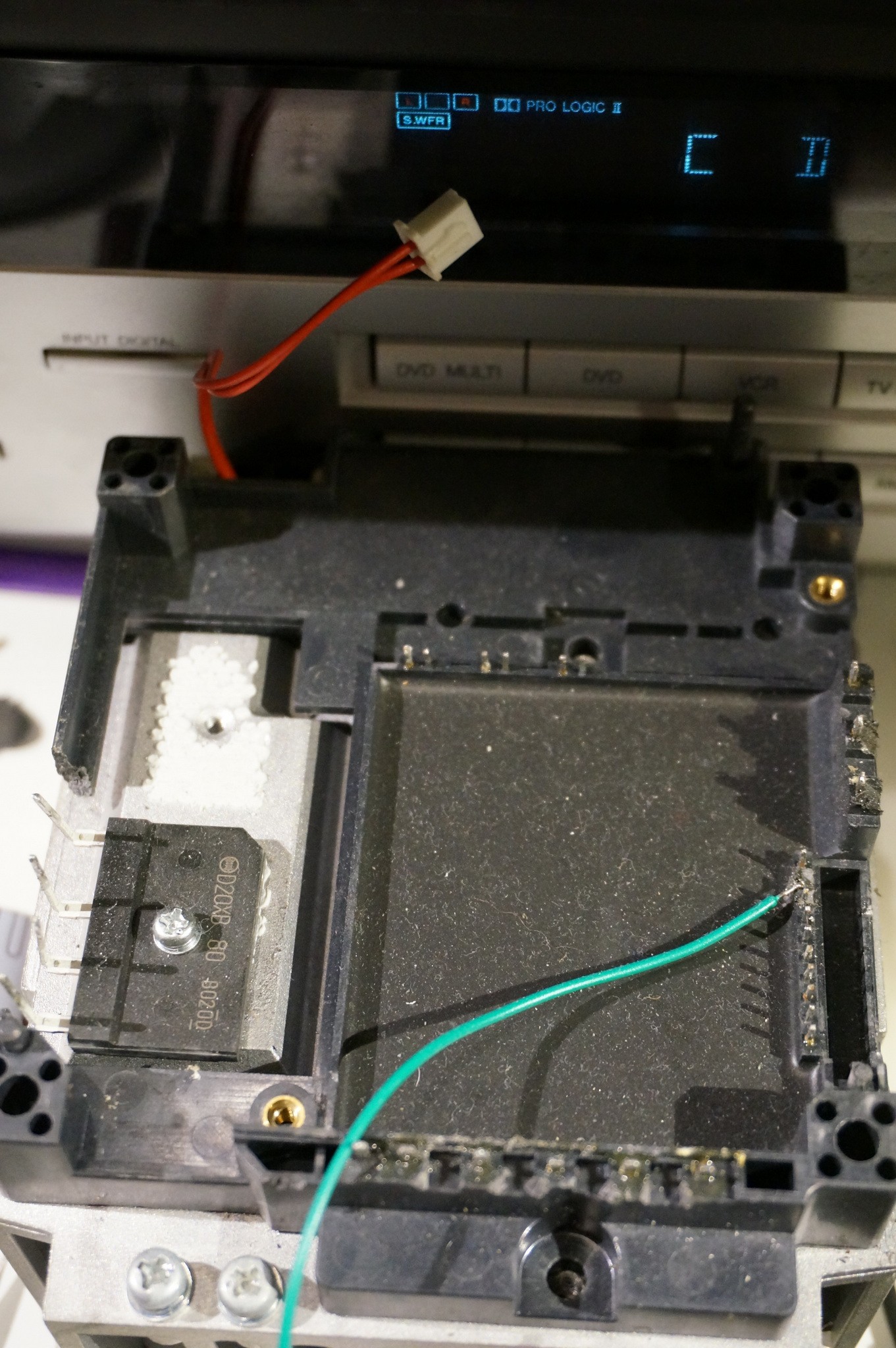 As you can see. I had it stripped all the way down to the monolithic, custom made transistor block On the left, you can see the bridge rectifier used to supply the DC bus voltage.
Going clockwise around the transistor block, starting in the upper left we have
UEU, GU, VEV, GV, WEW, GW (Gate, and emitter contacts for the high side switches)
then we have power pins: B, -, +
TH, NSH1,COSH2,GB,COM,GZ,GY,GX,NSH3,N2SH4
Lastly we have power pins:
W,V,U,<can no longer remember but probably another negative>, PD, TRG
I accidentally one of the pins, so had to solder on the green jumper to repair it during the reassembly. Fortunately it was a signal pin so a short jumper will not be too detrimental.
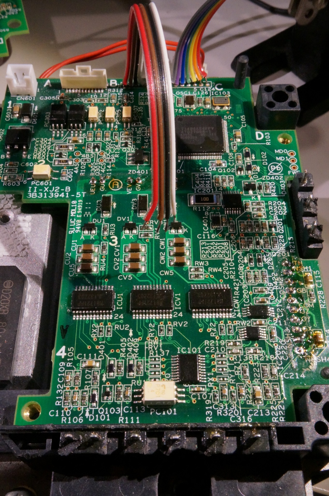
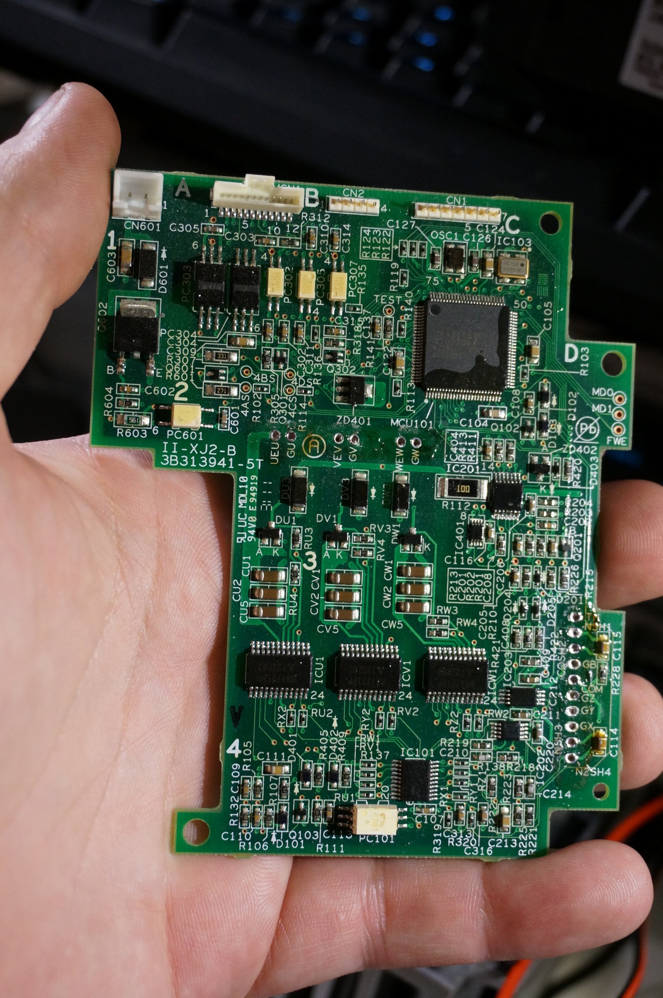 Main controller and gate driver board.
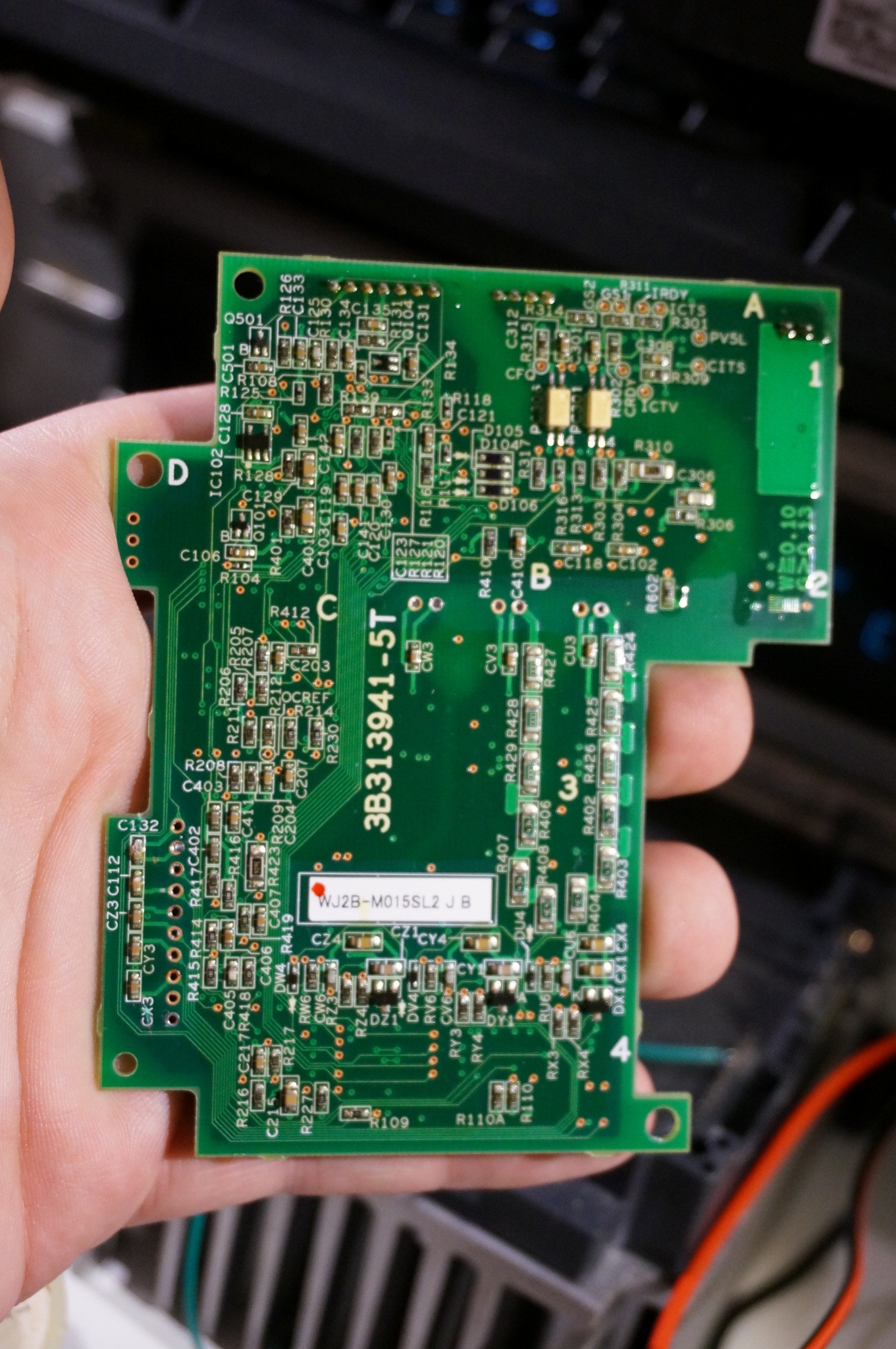
Back of the driver board
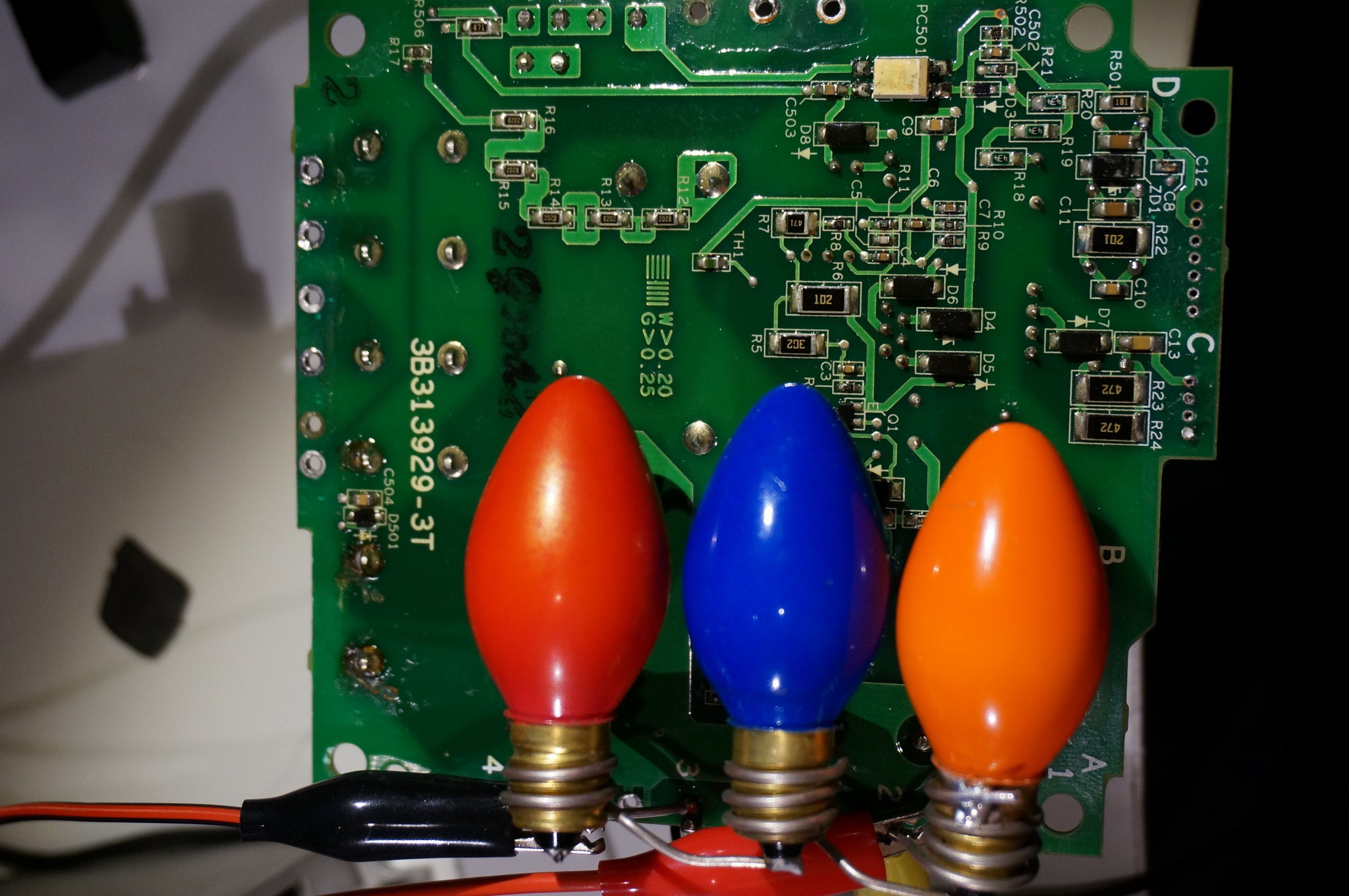
My ghetto safety system. (If it's stupid but it works, it's not stupid) I wanted a way of quickly and safely discharging the inverter's 4x 470uF capacitor bank charged to 300v
My solution: 3 120v 5w Christmas light bulbs wired in series across the bank.
Clear and visible indicator that it's hot, and it doubles as a discharge load. It's dead in <10s (as opposed to the built in discharge system that says 10 min)
(I did this again across a voltage doubler I was using to provide the 300VDC to test this unit
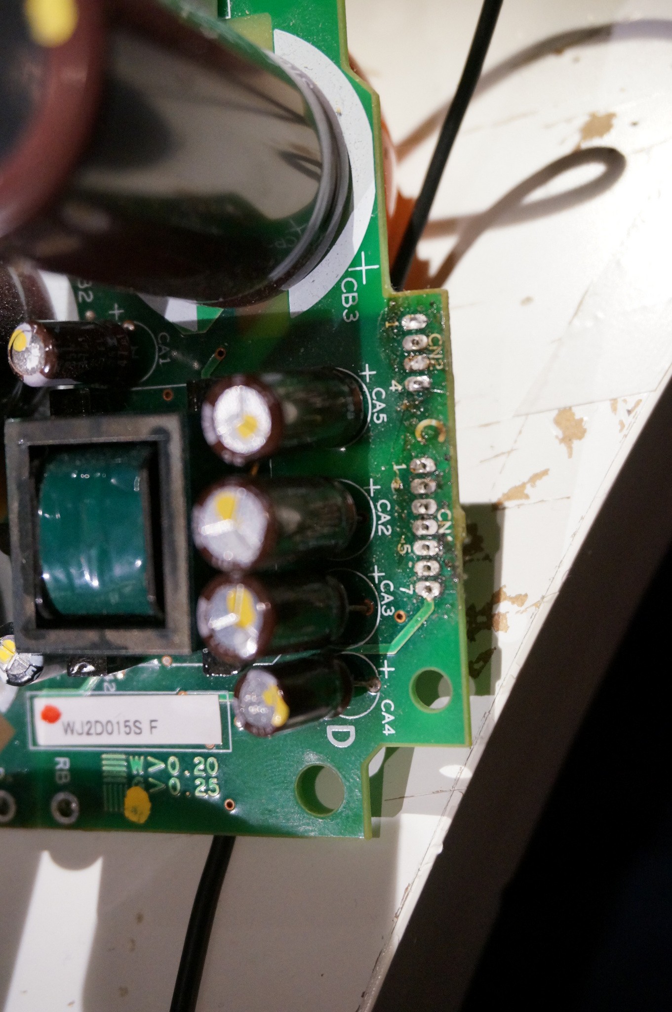
Here's the board-board interconnect that I butchered.
It provides a 28ish VDC isolated floating supply that is used to supply the high side gate drivers
it also provides a 5V and a 28ish VDC supply for other functions that are semi isolated from each other
There's also what I believe to be an opto isolated zero crossing signal of the incoming mains and another signal of the bank voltage.
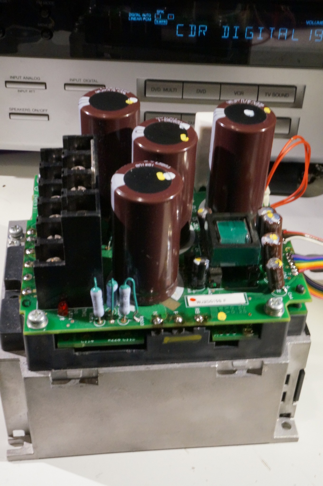
Here's the main board soldered back in place. with my replacement jumpers between the power board and the gate driver board
Fully (electrically) assembled
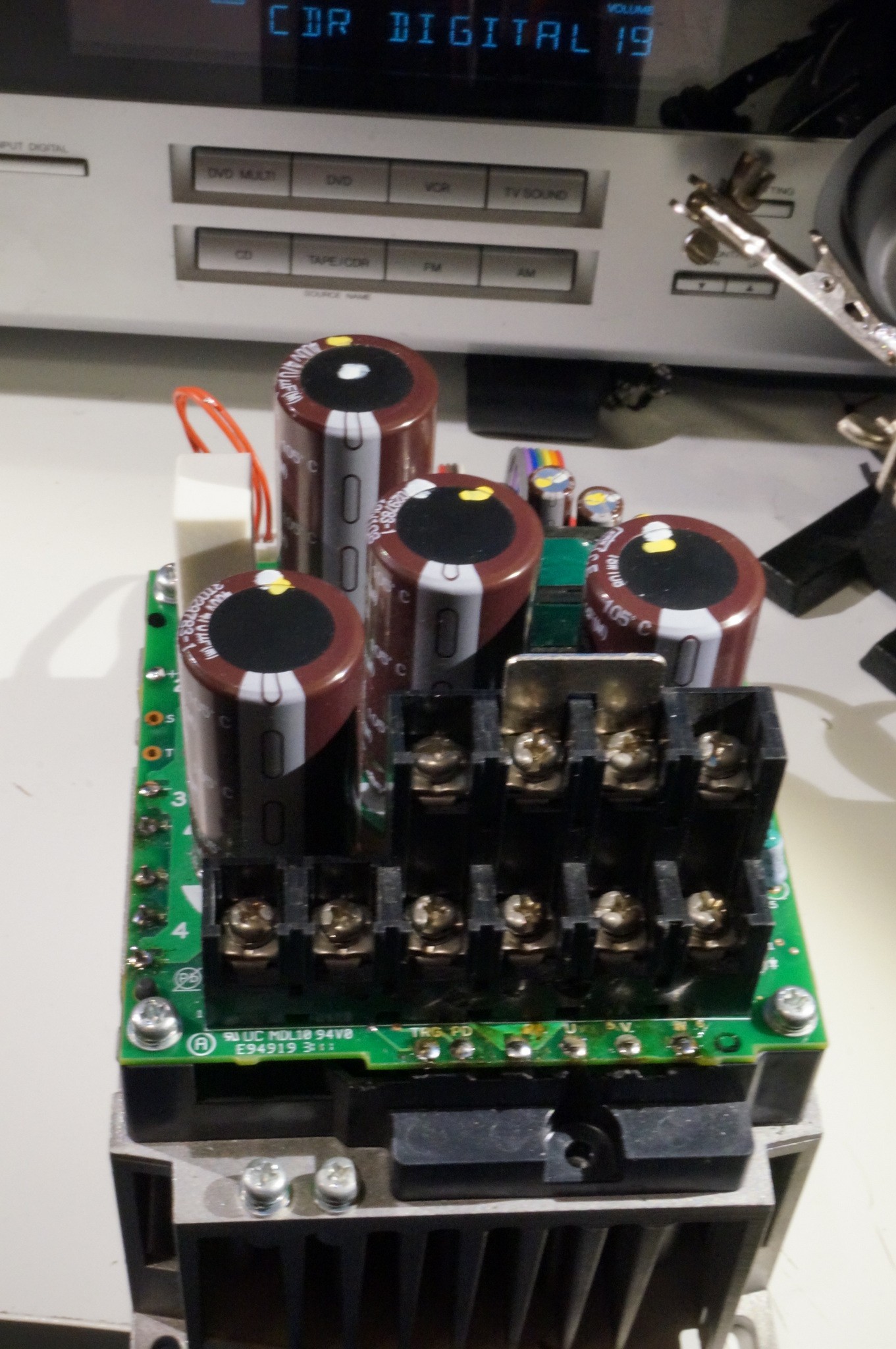
Side view. It has provision for 2 bridges to give it 3phase input, but they only populated one of them. (if I had known this I would have gotten one of the slightly cheaper 3ph versions :| )
(sorry about the blur) End view of the inverter showing my jumpers. If they had used 2.54mm headers instead of 2mm jumpers I would have use the multitude of headers I have in stock... <sigh>
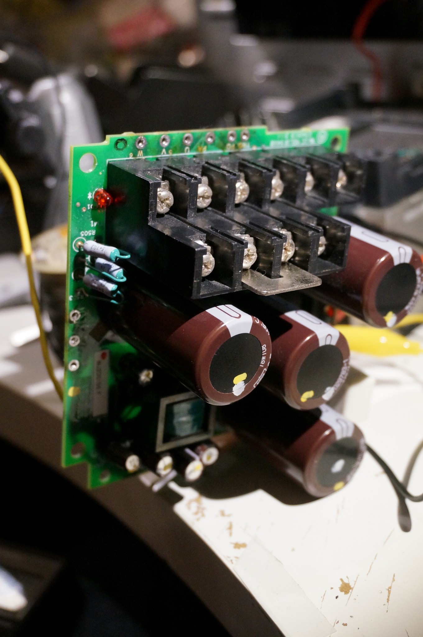
 Other side view. Here you can see the power indicator LED nestled in the lower right, and the self
discharge network right next to it.
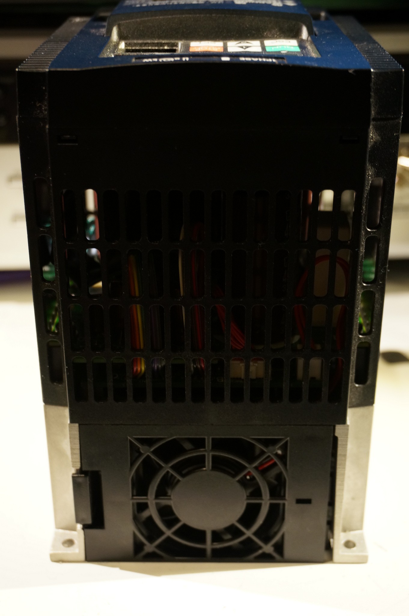
Fully closed up! the jumpers fit just fine in there.
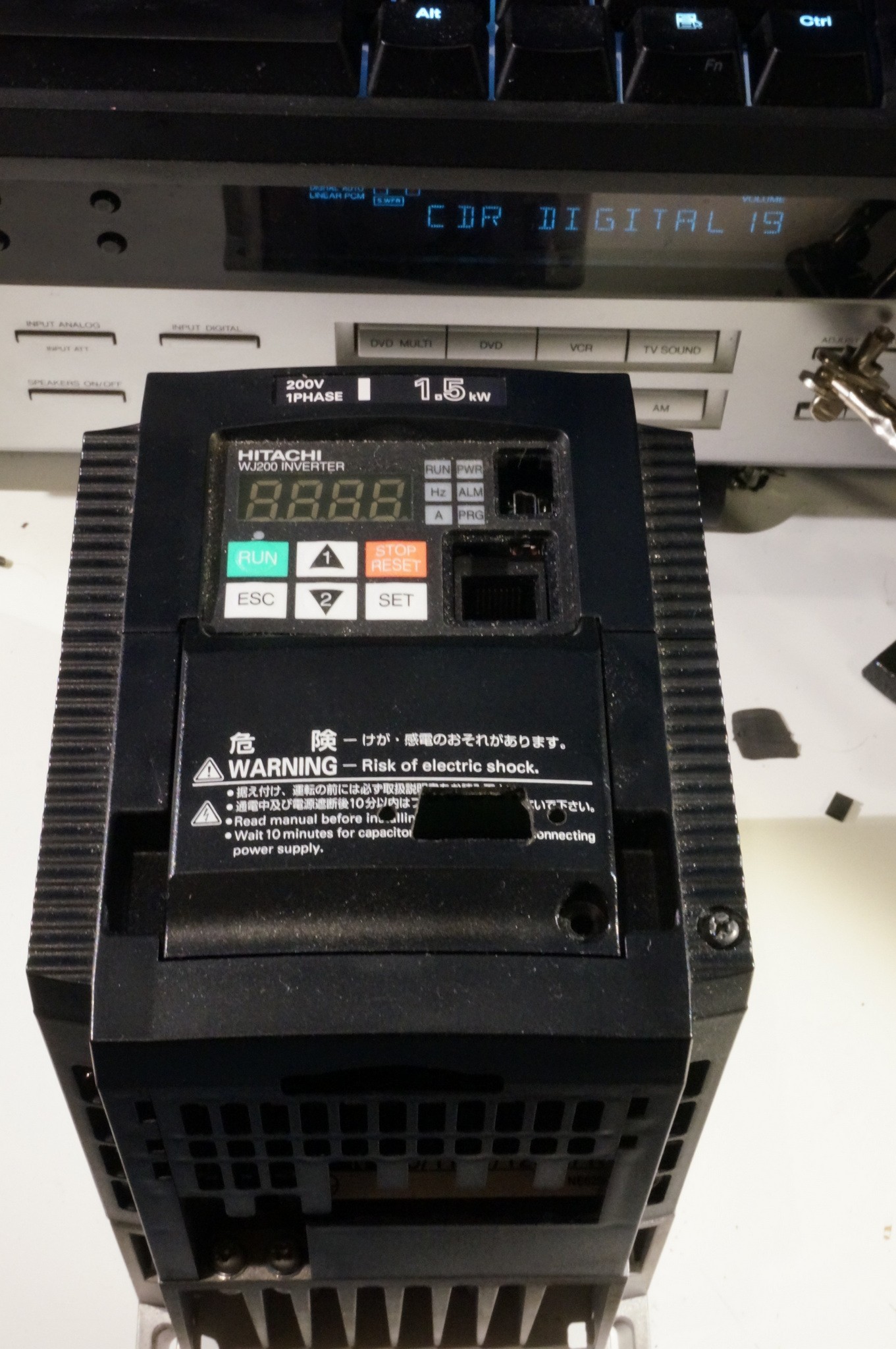
Fully (re) assembled. You can see the cutout I made for a DB-9 jack I was going to use for a pendant.
Maybe I'll rework it to use the RS 422 jack there next to the display instead. Make a microcontroller based pendant. Arduino of course. For blog cred :)
Hope you enjoyed this look.


 Jbarlow1007
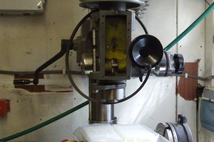
 Sci
Sci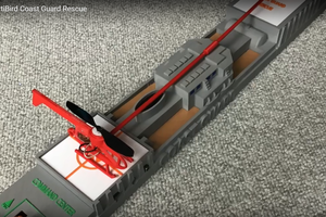
 Luke J. Barker
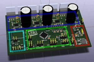
can you post schematic ?