 rlsutton1
Basic Localisation and routing is implemented as can be seen above in the video.
Speed control - the speed of each track is regulated by a PID using feedback from the quadrature encoders.
Directional control - a PID monitoring the heading as determined by dead reconning splits the desired speed between the two track controllers, and when the vehicle is stationary it applies opposite speeds to the tracks to rotate on the spot.
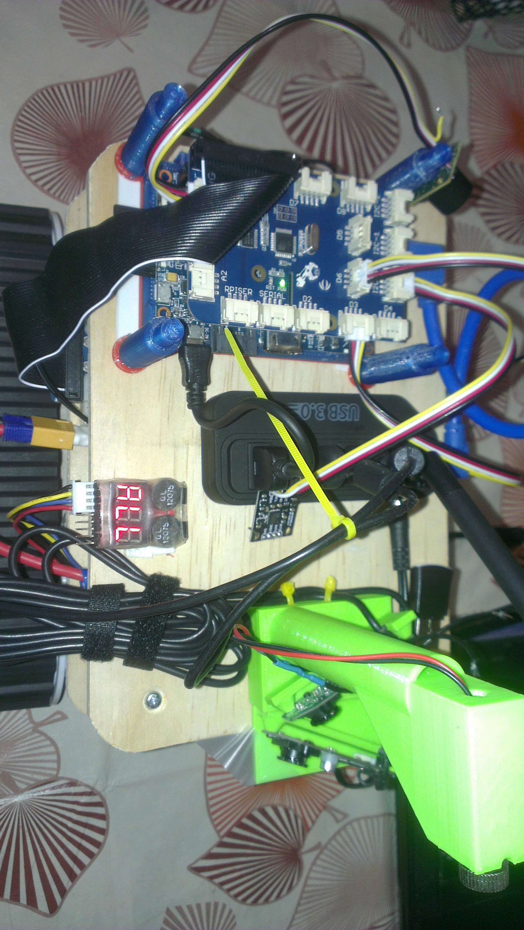
Power supply - 2 separate switch mode regulators are used, one to supply power for the motors via the hbridge and another to power the raspberry Pi and other devices.
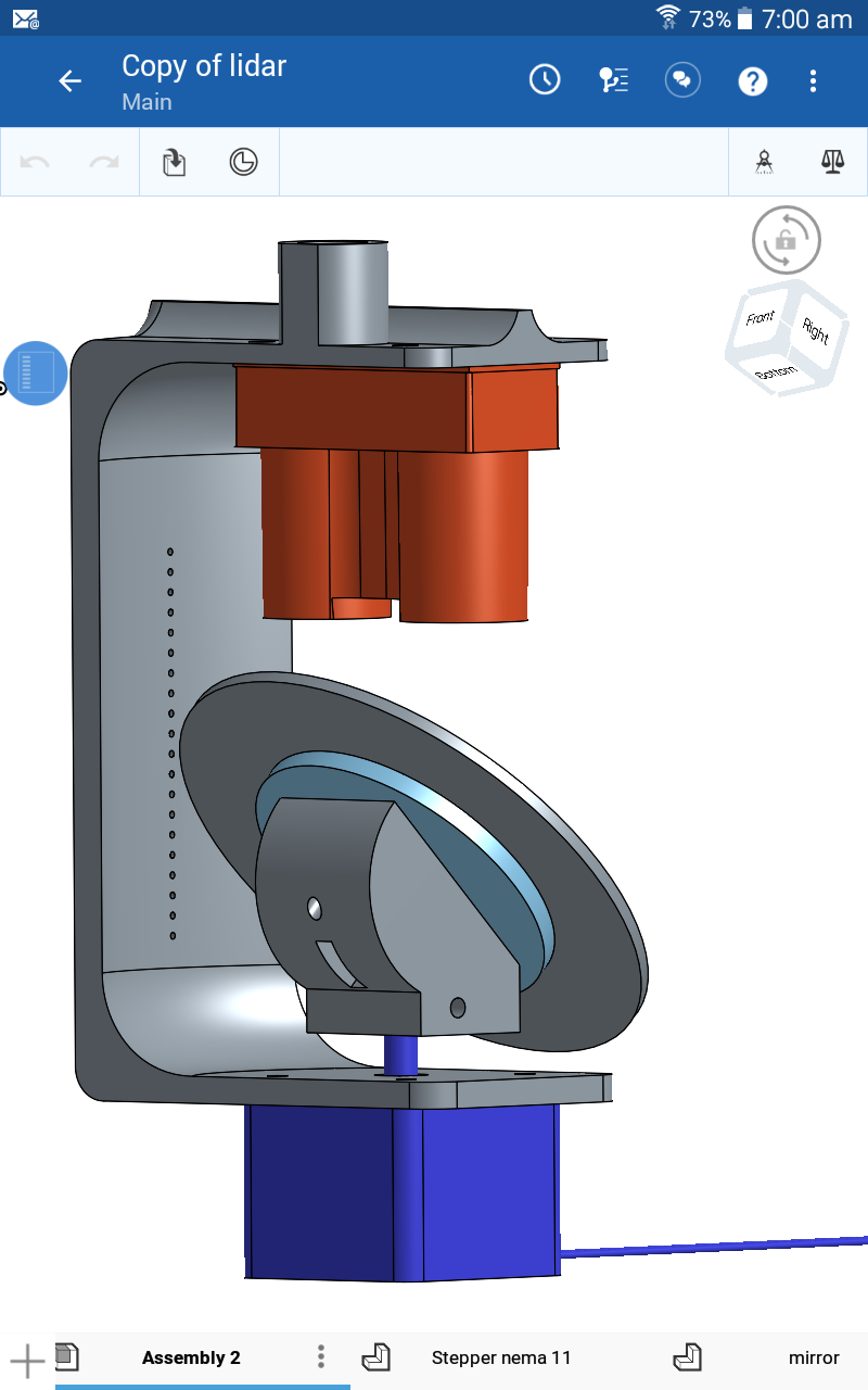
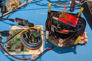
The power systems consisting of battery, 2 switch mode power supplies and an hbridge are on the lower layer. The Pi and sensors are on the upper layer separating them from the electromagnetic fields of the power systems. The compass is elevated on a pole for further isolation from magnetic fields which is particularly important for the compass.
Laser range finding is achieved with a LidarLite mounted over a stepper motor rotating a mirror mounted at 45 degrees.
Although autonomous operation is the intent, a very basic user interface has been built to allow control of the bot for testing purposes. Simple operations such as setting the heading, forward & backward speed are implemented, as well some feed back on the current heading of the robot.
Next SLAM (Simultaneous Localisation and Mapping) will be tackled.


 Gertlex
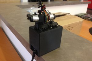
 Jason Wood
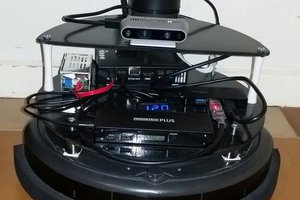
 Thornhill!
With that said you may want to look into writing a small C program to do the encoder counting and using some simple IPC (inter-process communication) to get the data from the C program to your java program. A look at this website, http://research.engineering.wustl.edu/~beardj/CtoJava.html , may get you started. Otherwise, as you stated, your next best step is to move the encoder counting to external hardware.