0%
0%
R.Hasika - a precise and compact robot base (rpi)
A precise and upgradable robot base built around a raspberry pi
 Audrey Robinel
Become a Hackaday.io member
Already have an account? Log in.
Just one more thing
To make the experience fit your profile, pick a username and tell us what interests you.
Pick an awesome username
hackaday.io/
Your profile's URL: hackaday.io/username. Max 25 alphanumeric characters.
Pick a few interests
Projects that share your interests
People that share your interests
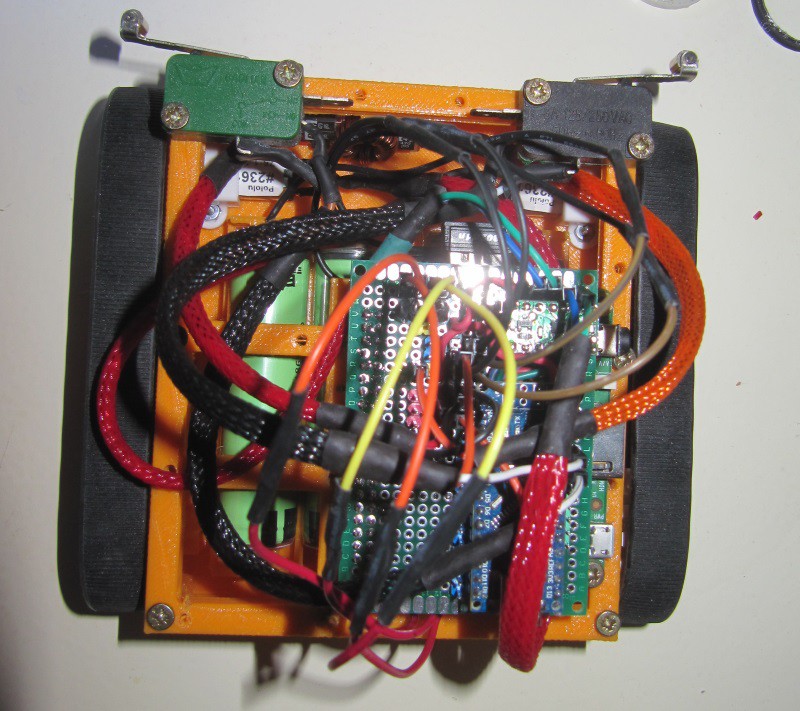


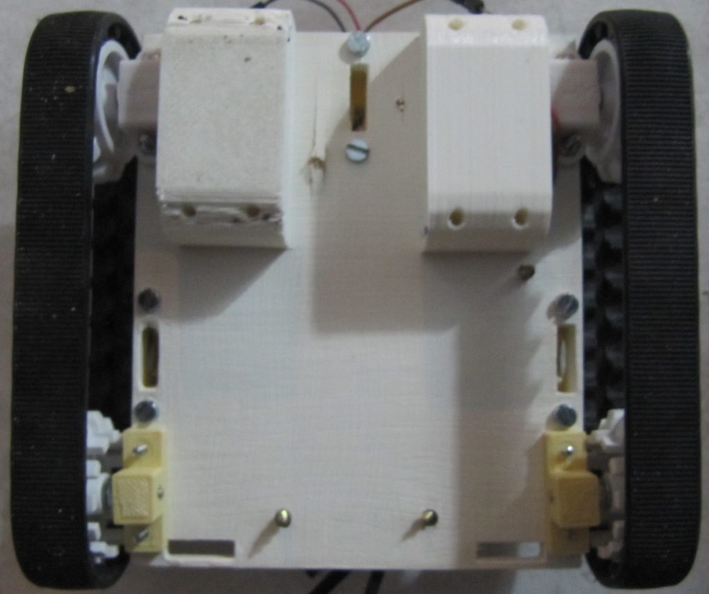
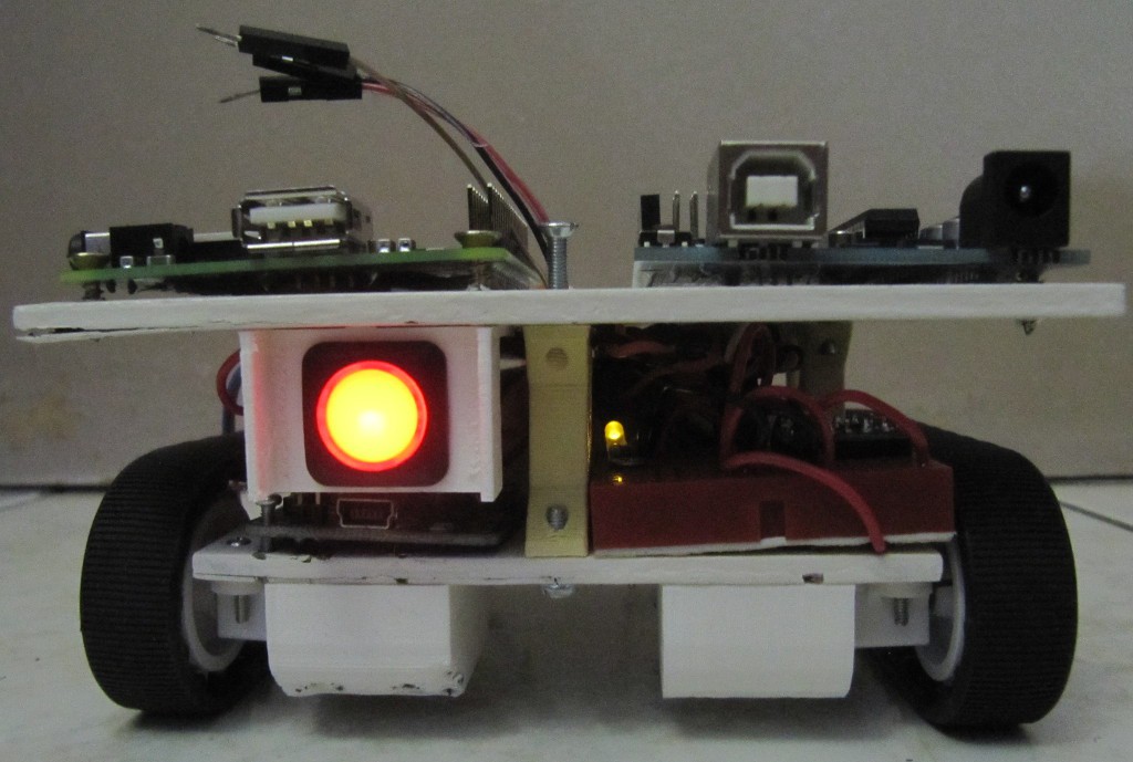
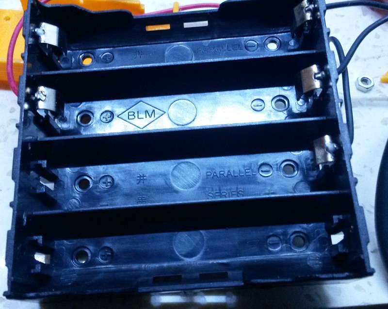
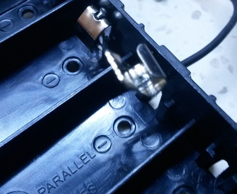
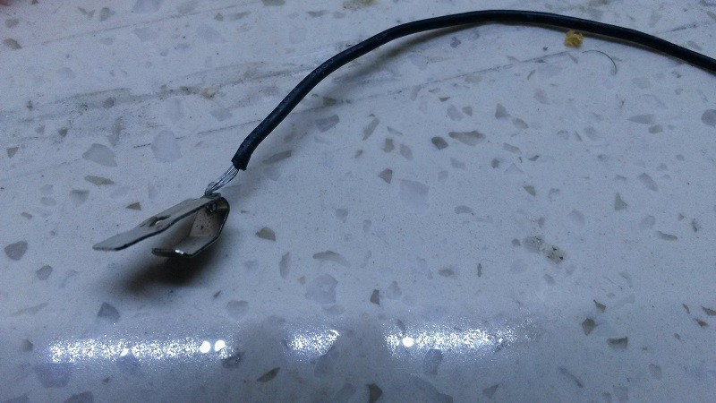
 As seen in a previous project log, i have two plates for this robot. The lower one sports the battery, charge circuit, power regulator, motors, ultrasonic sensor and the motor driver.
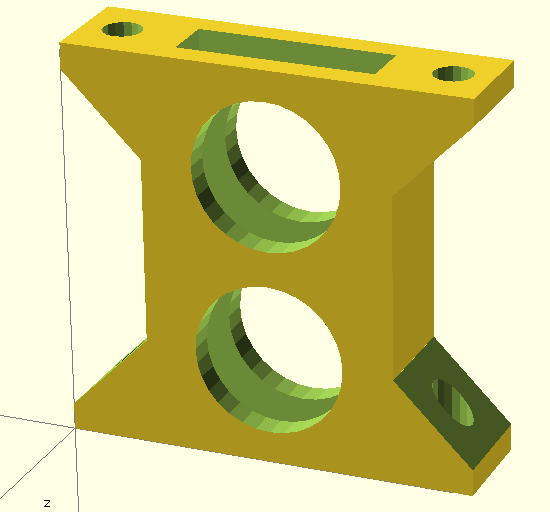
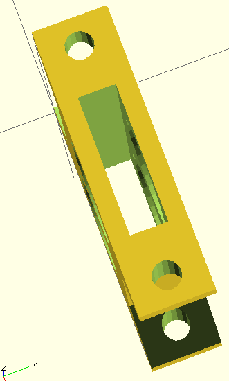
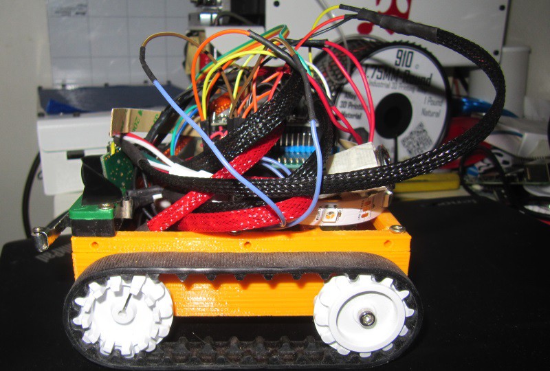
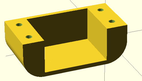
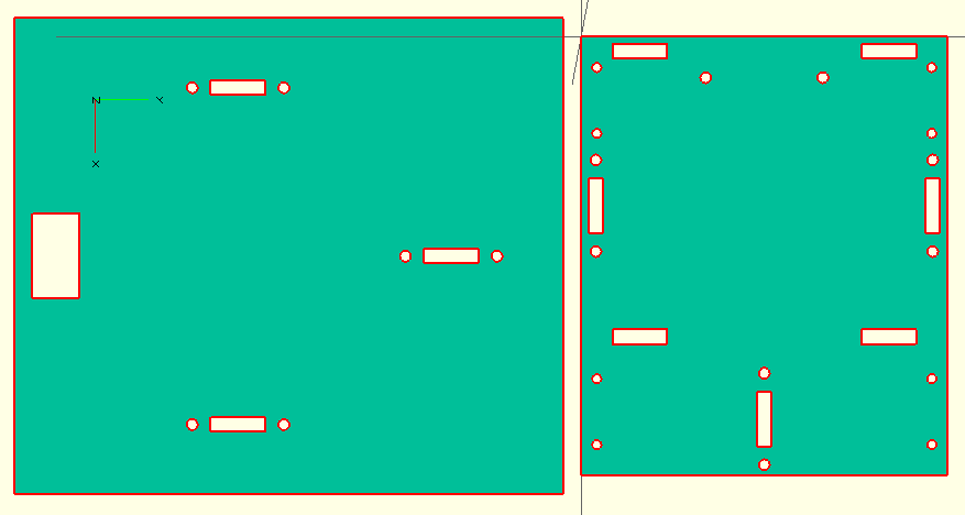
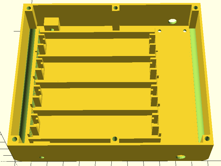
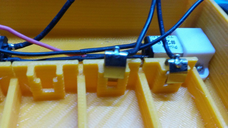
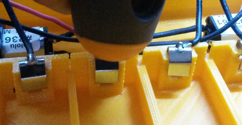
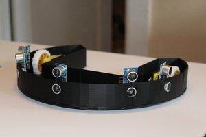
 Of course, the chassis plate have been designed to work with those beams, as not only the screw holes are present, but rectangular cuts on top and bottom, aligned so that this positions the top plate adequately in relation to the bottom plate.
 I could have printed it nicer, but it does the job perfectly as is.

 Russell Cameron
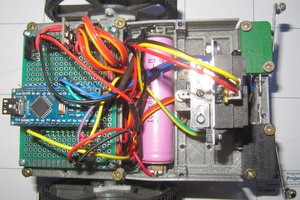
 Keith Elliott
 Roger
Roger