Close
0%
0%

3D Printer

Attempt to dive into 3D printing

Similar projects worth following
The goal is to build a 3D printer from parts on hand and little parts ordered. I am unsure about the controller yet and am using this to document ideas and possible solutions.

3D Printing Concepts:

http://3dprinterplans.info/how-to-3d-print-beginners-guide-to-3d-printing/


3D printing process:

FDM


FDM specific Concepts:

  1. Filament
    1. http://www.matterhackers.com/3d-printer-filament-compare
    2. http://www.protoparadigm.com/news-updates/3d-printer-filament-buyers-guide/
    3. http://www.3dprinterpro.com/go/3d-printer-filament/
    4. http://www.matterhackers.com/articles/how-to-succeed-when-printing-in-pla

3D printing flow:

software to create 3D model >> software to "slice" 3D model >> software to send it to 3D printer >> 3D printer firmware (interprets commands for movement)

These sections will utilize the following hardware:

  1. Computer to be used up to sending the program to the 3D printer
  2. Printer Mechanical
  3. Printer Electronics

3D modeling software:

To be determined. . .

3D slicer:

Repeteir Host


Sending Commands to Printer:

This hinges on what printer electronics are used. Either to have Repetier control the printer direct, or to drop some G-code onto an SD card that is used by the printer.

Currently using Repeteir Host to send G code commands to UNO without use of SD card. Would like to have SD card capability.


Printer Electronics:

Not sure which direction I will go yet (not in the order of preference):

  1. Smoothieboard
  2. Teensy 3.1 / RAMPS
    1. https://community.freescale.com/projects/freescale-based-3d-printer/blog
  3. Mega / RAMPS
  4. **Currently testing with Teacup without RAMPS board** UNO / RAMPS

Printer Hardware:

  1. **Not Used** The first go around of this will just be a simple x/y/z table that I had built long ago using a scanner bed. The bed has been scavenged for the mill, so a new one will be needed. Modification will be required.
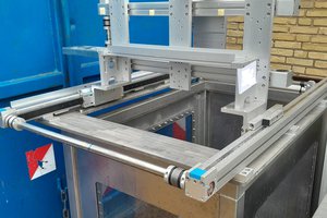
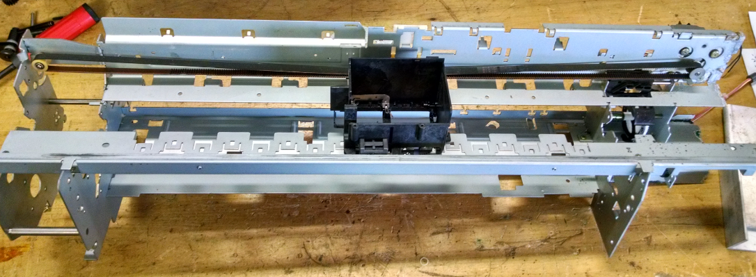
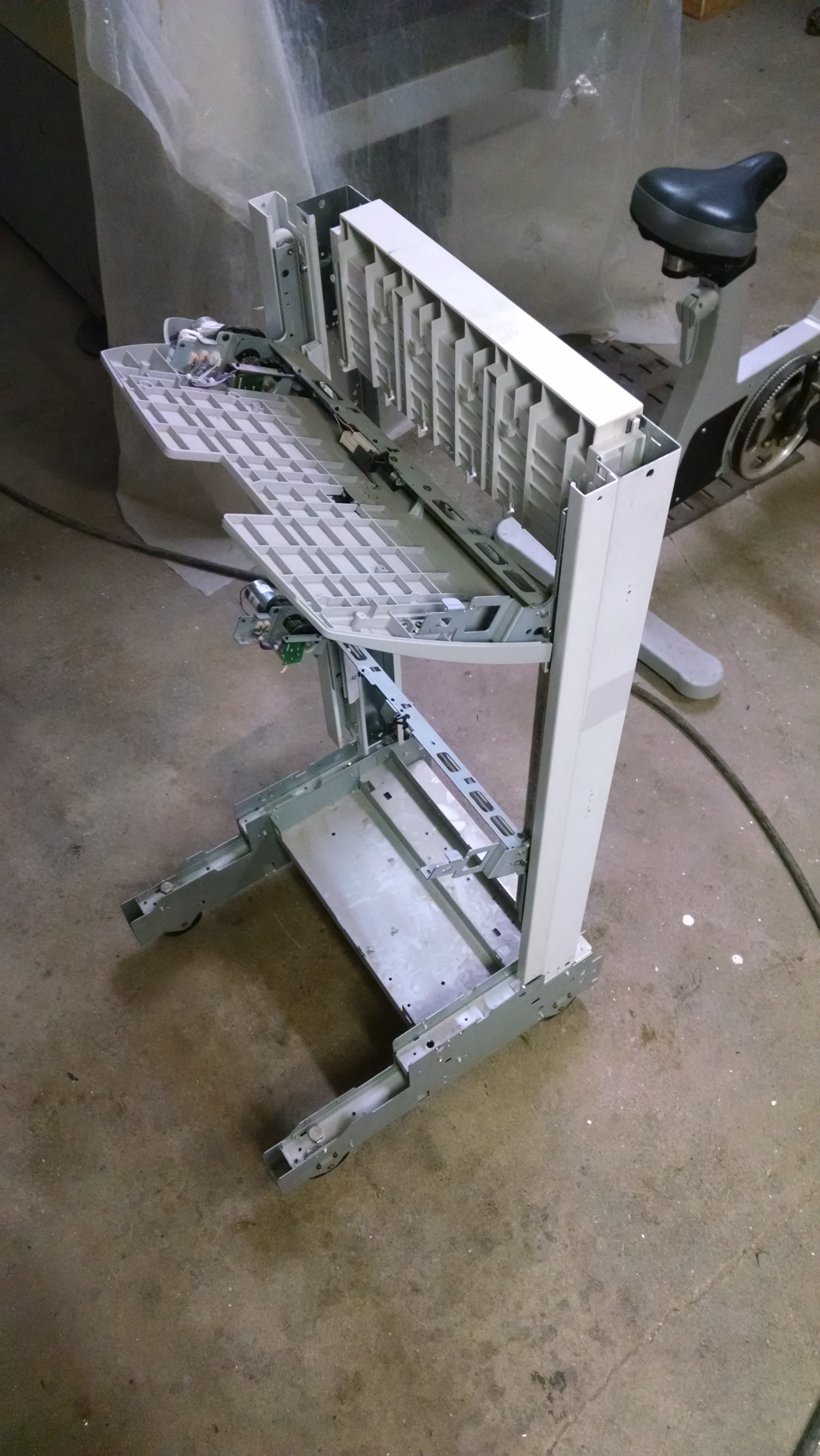
  2. Looking at the stripped printer/copier parts I have on hand, I am leaning towards using a copy machine scanner bed as the y axis, a stepper driven printer as the x axis and a copy machine paper selection tray as the z axis (which uses a rack and pinion). This would be a mix match of parts, but it would give me more travel than the prior hardware option.
    1. Y axis
      1. Copier Scanner bed carriage is in progress
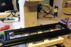
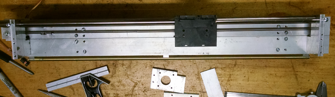
    2. X Axis
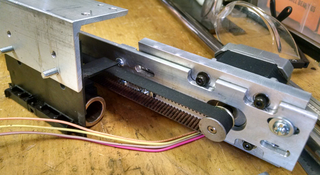
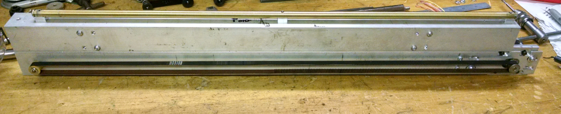
      1. Using same style of industrial printer that was used for claw machine. This is longer than is needed, but everything else I had would not be long enough.
    3. Z Axis
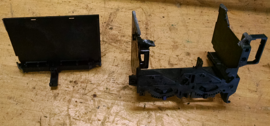
      1. The paper selector has been chosen, but nothing more has been done.

Printer extruder. Intentions are to build one.

Extruder design options:

  1. http://www.3ders.org/articles/20131231-all-metal-next-gen-3d-printer-extruder-from-micron.html
    1. Removable Nozzles
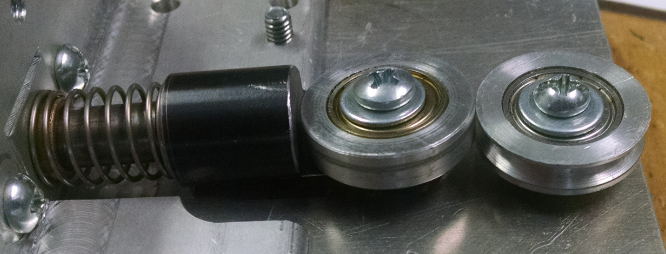
    2. Spring loaded tensioner for clamping onto plastic wire
  2. MB Plus RepRap Hot End (on Thinigverse)
  3. http://reprap.org/wiki/Geared_extruder_nozzle
  4. http://reprap.org/wiki/Extruder_Nozzle_Variation
  5. http://reprap.org/wiki/Hot_End_Comparison

Extruder wants. (keep in mind I have no experience in 3D printing):

  1. Be able to switch between 3mm and 1.75mm
  2. Removable nozzles to switch between different sizes

  • X Axis Motion

    willbaden09/22/2015 at 11:34 1 comment

  • X Axis part 2

    willbaden09/22/2015 at 03:41 0 comments

    Now that the upper guide is mounted, the lower guide and upper bearings can be added. The lower guide is mounted with a couple of aluminum pcs. These mounts were bored out for a snug with with the lower guide:

    The mounts were then relieved to allow for the belt to pass under. This allows the mounts to attach on the upper part.

    These were then mounted to the x axis. The lower guide was ran through the holes and fastened using screws to fasten them.

    Next the plate that mounts to the old printer ink carriage was made. This will connect the upper right angle bracket to the old printer ink carriage. The holes were center drilled in the mill/drill and then opened up using a drill press.

    The plate was mounted with the upper aluminum right angle. This was mocked up using some clamps to hold it in place and get measurements for the bearings that will be used.

    One of the bearings will be movable to allow for any irregularities of the upper shaft to be absorbed. This will use a plunger style of action, but will need to be kept from rotating around the plunger axially. The tension will be kept with a spring that was found in the parts bin from old copy machines and printers.

    The bearings were made to have v grooves machined into them to capture the upper guide. The outer section was made from aluminum and were pressed onto the bearings.

    Here is a picture of the plunger with the v groove bearing installed:

    The movable bearing needed to rest in a bushing block. This was a small piece that had two mount holes on the outside and a center counterbored hole that the bushing was pressed into.

    Mounting the bushing block and allowing the plunger to be mounted, the upper right angle needed to have relief slot cut into it:

    Mocking up the parts that were made showed that the bushing block needed some relief to allow for more tension on the spring that was used.

    To mount the rigid bearing, a flat plate with a slot was made. The slot will be used to keep the plunger aligned, preventing it from rotating. The relief allows for the plunger to move back and forth freely.

    Here is an assembly view of the plunger riding against the solid bearing. The upper guide rides between these.

    With it all assembled, the x axis carriage moves back and forth freely. Hopefully with the weight of extruders on the front, the rigid bearing will maintain contact with the upper guide. Now to mount the x axis to the z axis movement. . .

  • X Axis Build Part 1

    willbaden07/05/2015 at 04:58 0 comments

    Moving on to the X Axis. This axis will use the same printer/mechanism that was used for the claw machine build. It did start with the intentions of using the complete assembly, but later morphed into using only the carriage, belt, and motor combination. This is how the axis began life:

    The carriage will still be used and was modified to allow for an aluminum angle to be mounted to it. The carriage (printer head) had the cartridge holder removed. This was done with a hack saw.

    The leftover material from the cut was then milled down. This allowed an aluminum bracket to be mounted to it. The picture below shows the first location of the angle. This will have to be moved in the final assembly.

    Instead of using the original steel assembly, aluminum angles were opted to be used. They will sit one on top of each other. Starting with the lower angle, it will maintain the belt, motor, pulley moving mechanism.

    There will be a motor mount attached to one side of the angle. To aide belt tension adjustment, the motor mount fasteners holes were slotted. Further back from the end mill below are a couple of center drilled holes that will be used for the belt tensioner block.

    The motor mount that attaches to the angle, has a pocket CNC machined to accept the original motor. While in the CNC milll, the holes were also center drilled. After the CNC was finished, the holes were opened up to accept the fasteners.

    To allow for the motor pulley to sit in the center of the angle (top to bottom), the motor mount had a notch machined into the side.

    The screws that mount the stepper motor to the stepper mount required the aluminum angle to have slots for relief. First, holes were drilled out.

    Then the slots were finished out on the mill.

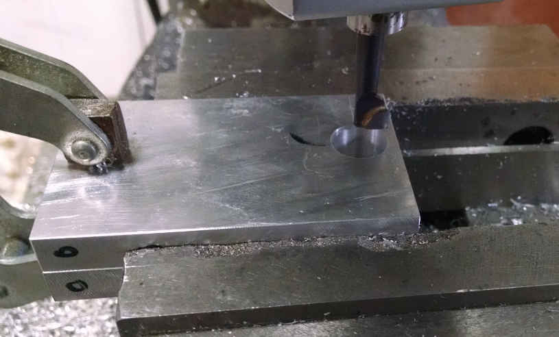
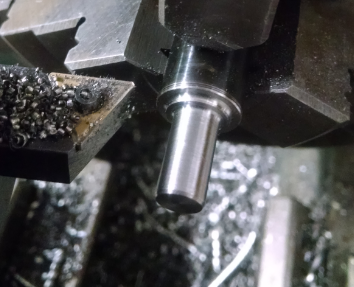
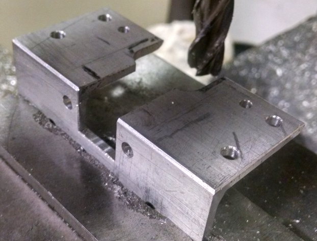
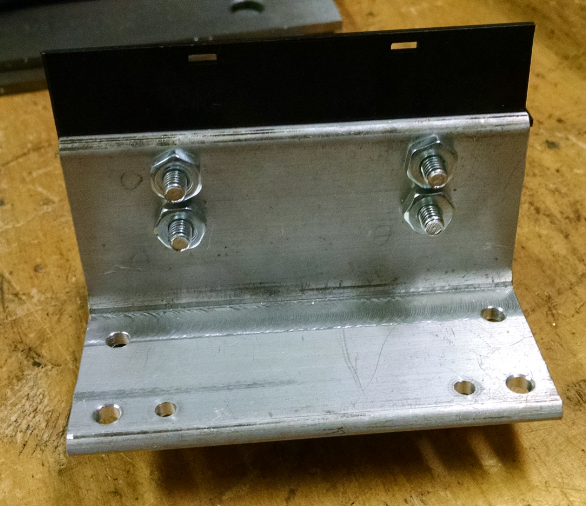
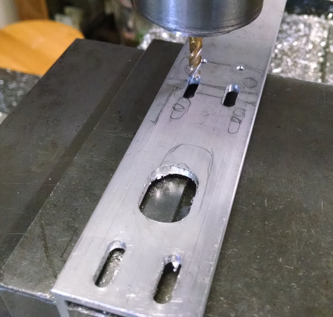
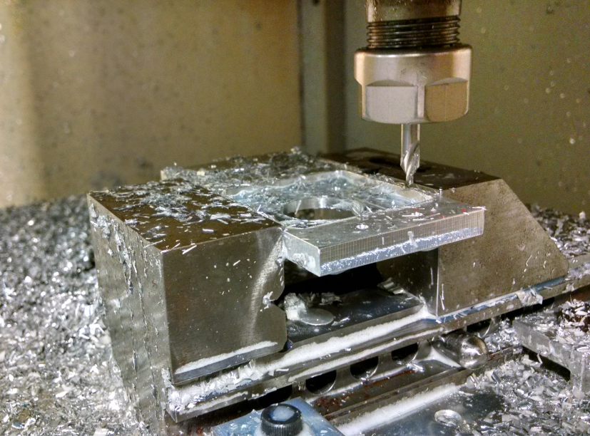
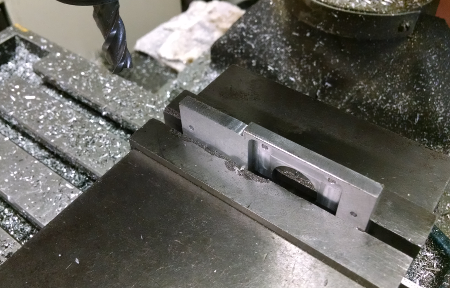
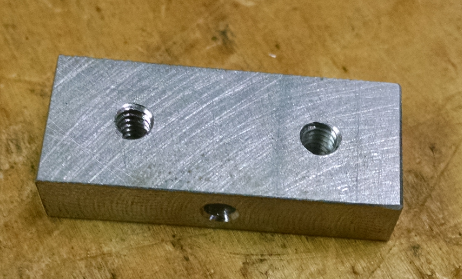
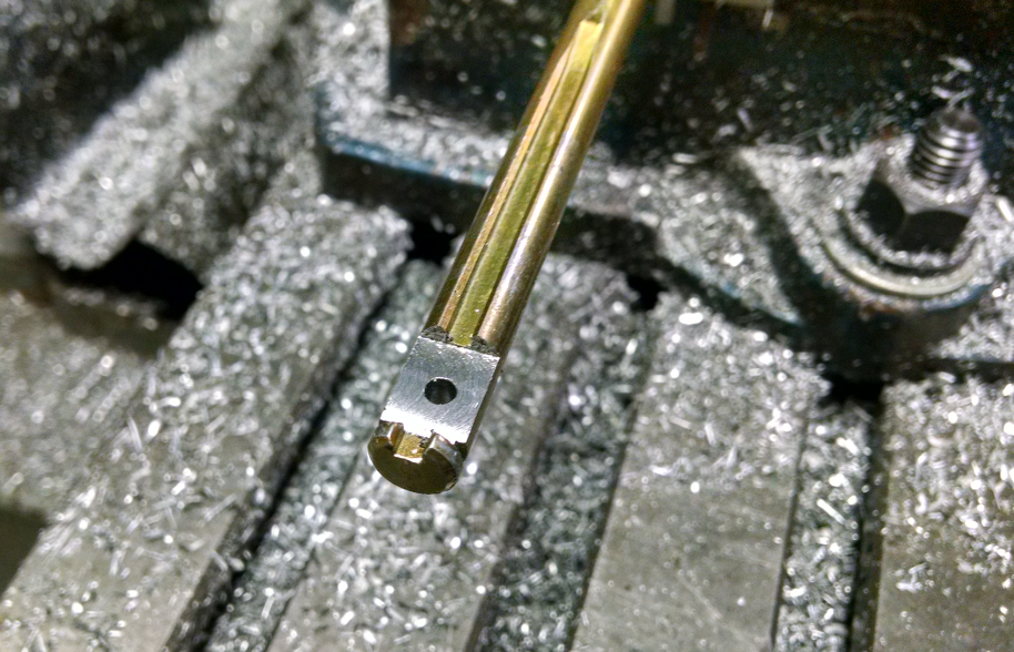
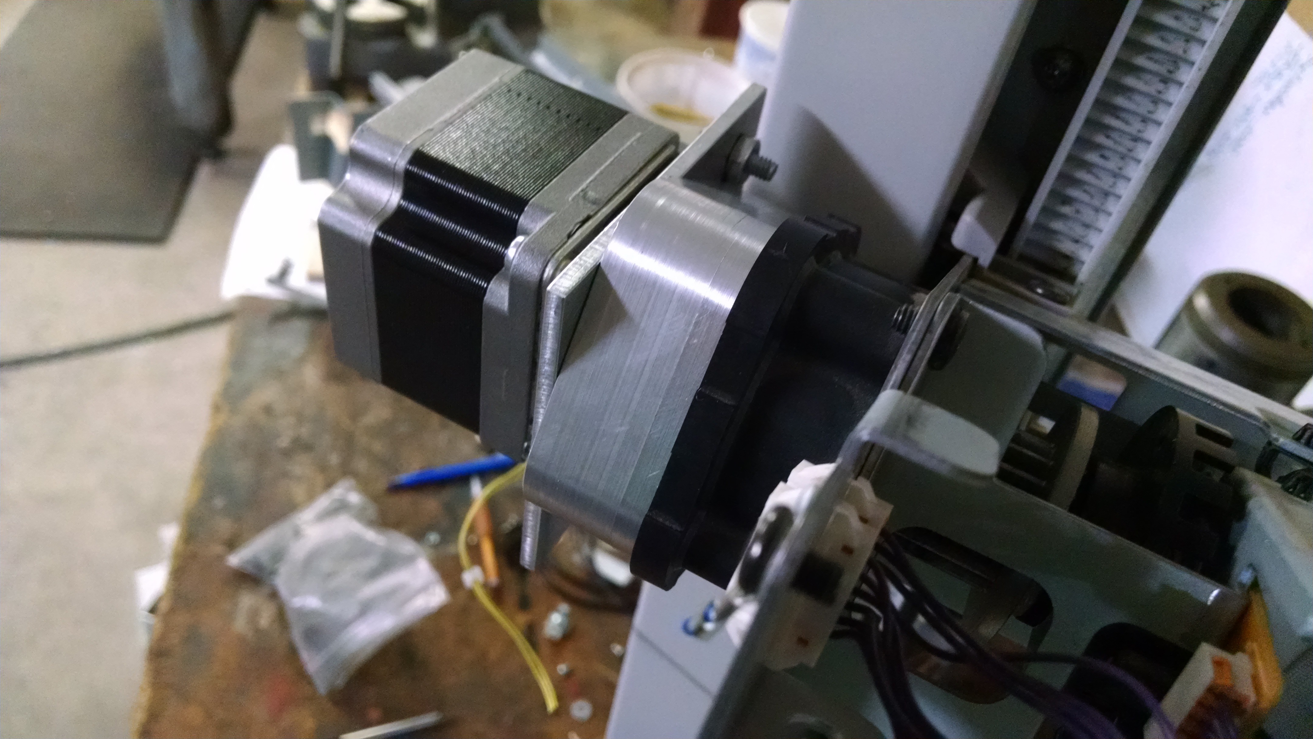
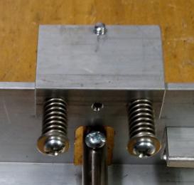
    The motor mount also required relief for the fastener washers. Using an end mill the counterbores were machined.

    Using a small piece of aluminum, the belt tensioner was machined. This had a cross hole drilled and tapped.

    The assembly was mocked up for fit. Note that the aluminum angle attached to the carriage is now mounted differently. This will allow a place to mount the upper bearings of the X axis.

    The upper aluminum bracket was then machined to length. It will be used to hold the upper steel shaft.

    The steel shaft had 3 flats milled with one drill and tapped hole in the center of each.

    These flats accepted aluminum spacers that allow for only 3 points of contact for the shaft.

    The upper and lower angles are mounted together using 2 shorter lengths of angle fastened with 8 screws per angle. They will be the center holes in the picture below.

    The next step is to make the brackets hat hold onto the lower shaft.

  • Z Axis Motion

    willbaden06/12/2015 at 18:07 2 comments

  • Y axis Motion

    willbaden06/12/2015 at 16:53 0 comments

  • UNO Stepper Tester

    willbaden06/12/2015 at 10:56 0 comments

    Since the axis are coming together, I wanted to be able to test the capability of the stepper motors without attaching a computer. The first test of the y axis included using Repetier host and an UNO using Teacup, which required hooking up the computer and sending G code to the UNO. Instead I wanted a pot to adjust the speed and direction of the movement. Here is what I came up with:

    /*
    Stepper Motor Control with Speed Direction outputs
    
    This program will send step pulses out to a step/dir driver board 
    for testing
    
    It is controlled by a potentiometer that will change the speed as it
    changes from 2.5V.  Below 2.5V is CCW: 0V is max speed, above 2.5V is CW:
    5V is max speed
    
    */
    
    //The lower the number the faster the speed
    // stepMaxSpeed = 15 is 15 uS delay between step pulses
    int stepMaxSpeed = 250;
      
    //The higher the number the slower the speed
    // stepMinSpeed = 100 is 100 uS delay between step pulses
    int stepMinSpeed = 1000;
      
    //Set pins for output to step/dir driver board
    int stepPin = 2;  //13 can be used for the LED
    int stepDirection = 3;
    int analogMotorControlPin = A0;
    
    //Analog value Read
    int MotorControlValue = 0;
    
    void setup() {
      // put your setup code here, to run once:
      pinMode(stepPin, OUTPUT);
      pinMode(stepDirection, OUTPUT);
    }
    
    void loop() {
      // put your main code here, to run repeatedly:
      int stepDelay = 0;
      MotorControlValue = analogRead(analogMotorControlPin);
      
      //Set direction and speed using the analog input
      // This has a dead band between 500-524.  Here the motor will not move
      if (MotorControlValue > 524) {
        digitalWrite(stepDirection, 1);
        stepDelay = map(MotorControlValue, 524, 1023, stepMinSpeed, stepMaxSpeed);
      }else if (MotorControlValue < 500) {
        digitalWrite(stepDirection, 0);
        stepDelay = map(MotorControlValue, 0, 500, stepMaxSpeed, stepMinSpeed);
      }else {
        //if analog input is in deadband, don't allow for pulses to be sent out
        stepDelay = 0;
      }
      
      if (stepDelay != 0) {
        delayMicroseconds(stepDelay);
        digitalWrite(stepPin,1); //step driver board
      }  
      
      //Delay microseconds for the driver board to recognize change
      // may need to be altered for the driver boarxd selected.
      delayMicroseconds(5);
      digitalWrite(stepPin,0);
    } 

  • Z Axis Modifications

    willbaden06/09/2015 at 02:51 0 comments

    The Z axis uses a tray selection option that was available for printers. It has two tray selection devices that could select where which slot the papers came out of. It uses two rack and pinions, one located on each upright. The location of the uprights was towards the center of the bottom cart.

    This was shifted towards what is now considered to be the back of the cart.

    The motors that were mounted to the tray selectors were DC motors. Instead of reusing them, stepper motors will be used. To mount them took a little bit of work. The gearbox is a planetary gearbox. This will allow or some good torque and the cogging of the stepper motor will keep the z axis in one location even if power is taken away from it.

    The original plan was to use the old dc motor mount, but the holes for adapting the motor weren't lining up as well as I had hoped.

    Instead a new aluminum cover was milled out from some scrap aluminum. Using CamBam to create the G code made life a little easier. The part was squared up with .020" per side oversize. This allowed for some cleanup and can be seen on the first side after being machined.

    Notice the square bottom. This was the part that was squared up and gave the vise something easy to hold onto. The holes that needed locating were just center drilled to allow for a drill operation on a drill press. The second side was then machined. This side just needed the 3 holes for the adapter plate located, the face machined flat and the outside profiled. If one would look at the lower half of the outside of the part, it can be seen that the top and bottom did not match up perfectly.

    And here is a view of the completed part. The center hole is used as a bearing for the center gear of the planetary gears. This bushing was from the idler shaft that was used in the DC motor design. It was pressed into the center of the housing and drilled out just large enough for the shaft to ride in.

    This was then mounted to the planetary gearbox.

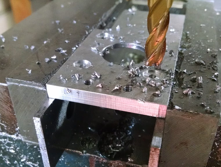
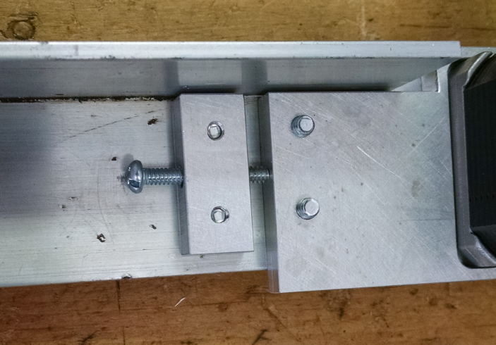
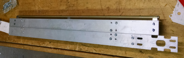
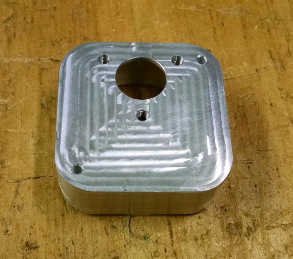
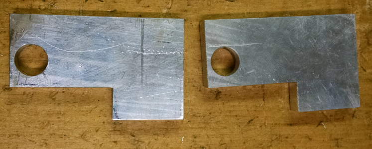
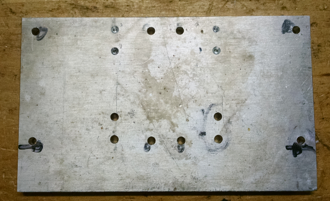
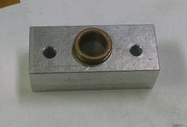
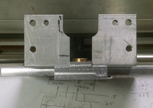
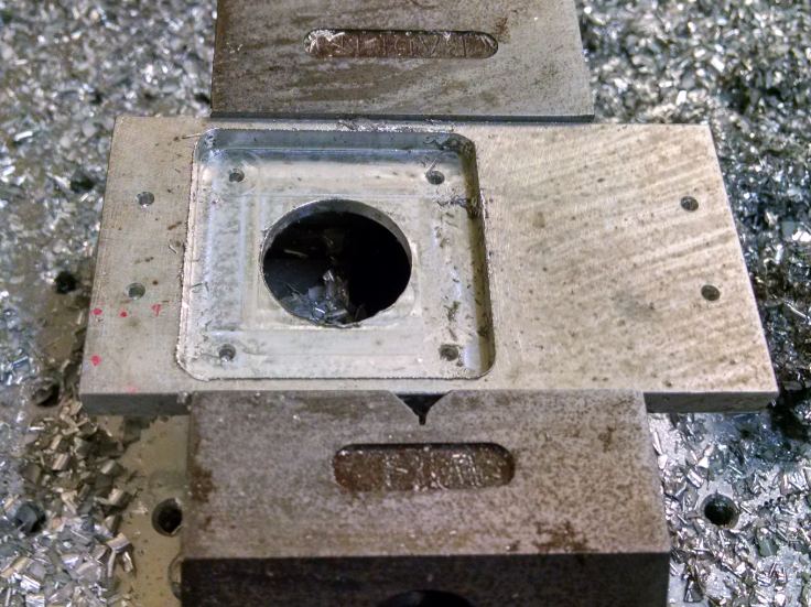
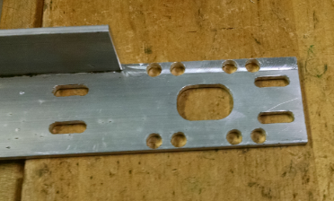
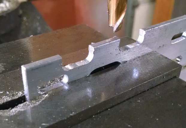
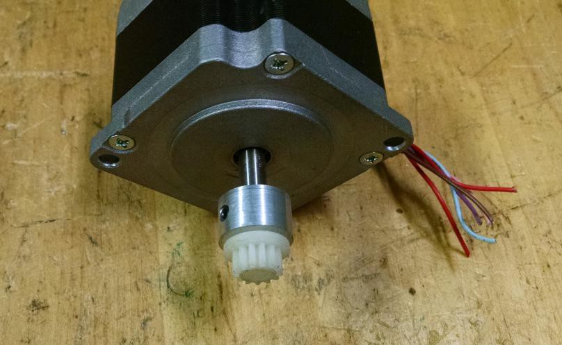
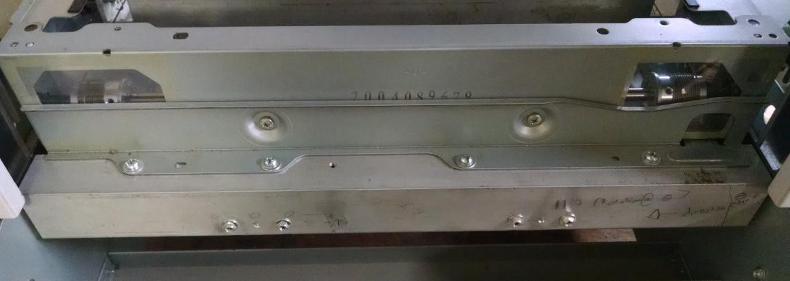
    Between the housing and the stepper motor, an adapter plate was required. This allowed for a larger motor mounting bolt hole pattern. Not as good looking as the housing but it got the job down with a few speed holes.

    Prior to mounting the stepper motor to the plate, the gear that engages the center planetary gear needed to have extra material added to it to allow for a setscrew to be used. Along with the set screw, the gear also had a slight press fit onto the shaft of the stepper.

    The motor was then attached to the planetary gear.

    The next step is to test the z axis and verify operation. The plan is to use a simple UNO program that can send a variety of speeds and duration to the motor. This will be a different way to test the axis compared to the Y axis test that used Repetier Host for the testing.

  • Y axis Mounted

    willbaden06/09/2015 at 01:54 0 comments

    The Y axis has been finished to the point of being mounted onto the paper tray dispenser that will become the Z axis. The up and down movement of the Y axis is limited by the spring loaded shaft that runs along the X axis. The shaft shown in the middle of the picture below is spring loaded with a bearing attached and will push up on the lip that the upper bearings ride on.

    This shaft extends to the other side with another bearing and spring to produce the same effect.

    To keep the y axis located left and right, there is a single spring loaded bearing that pushes the two bearings on the other sides steel wall. (as seen in the picture above). Below is an outer view of the spring loaded left/right tensioner. Followed by an inside view showing the springs on the shafts that maintain the springs.

    On the underside of the y axis is a flag for the opto sensor. This will sense the minimum y axis location. Sensing the home position.

    And the opto sensor.

    This was all mounted to the paper tray. The back was mounted to an existing cross brace with an aluminum angle. The existing hole locations were measured and reused.

    The front required a couple of uprights with some holes added to the paper tray. A horizontal angle was then mounted across the top. The upper holes were slotted, so it could be fine tuned to be parallel with the X axis that is yet to be mounted.

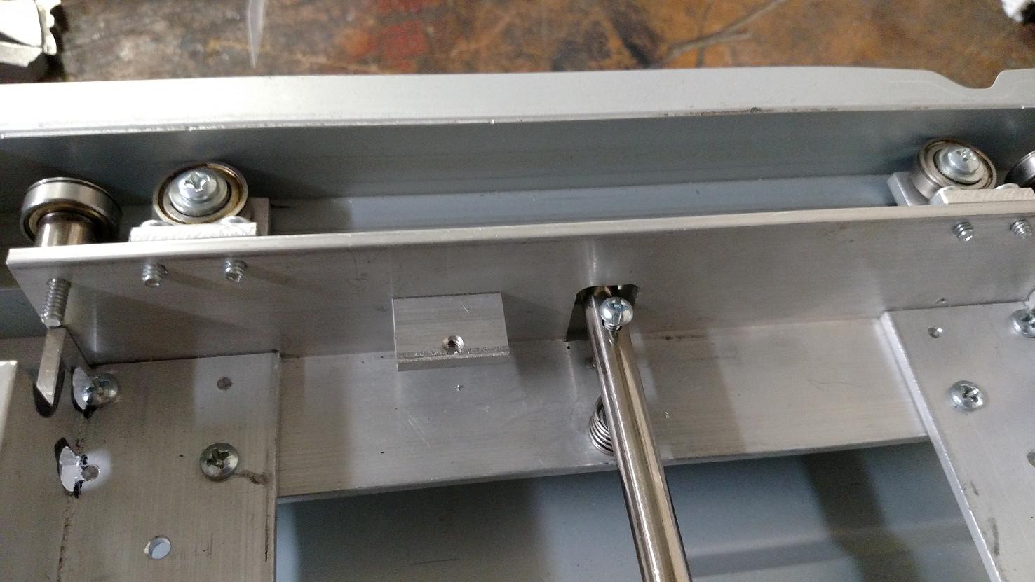
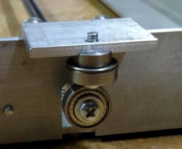
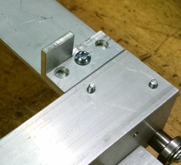
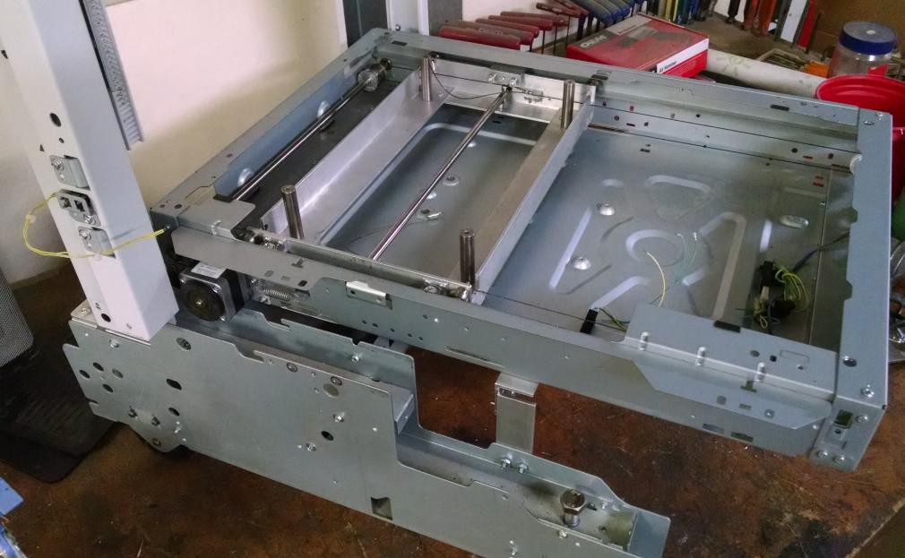
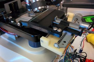
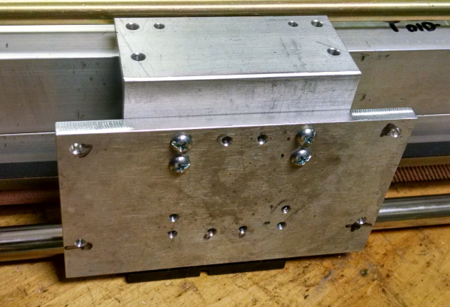
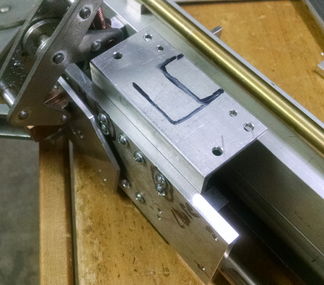
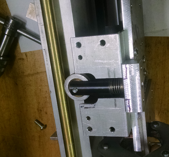
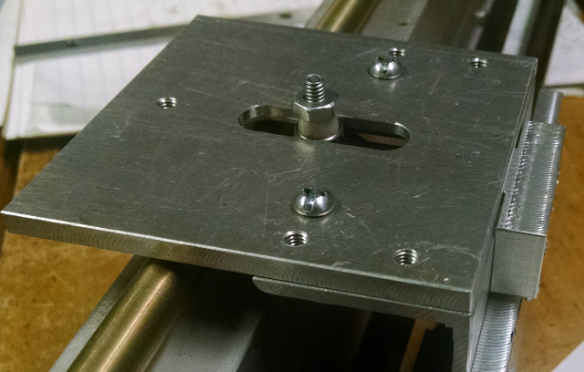
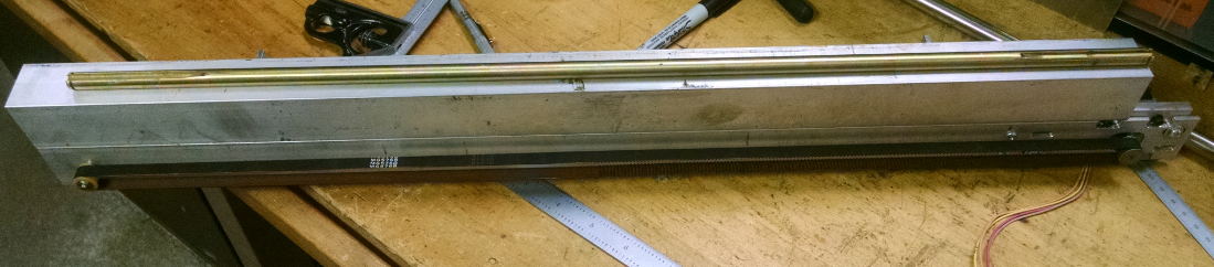
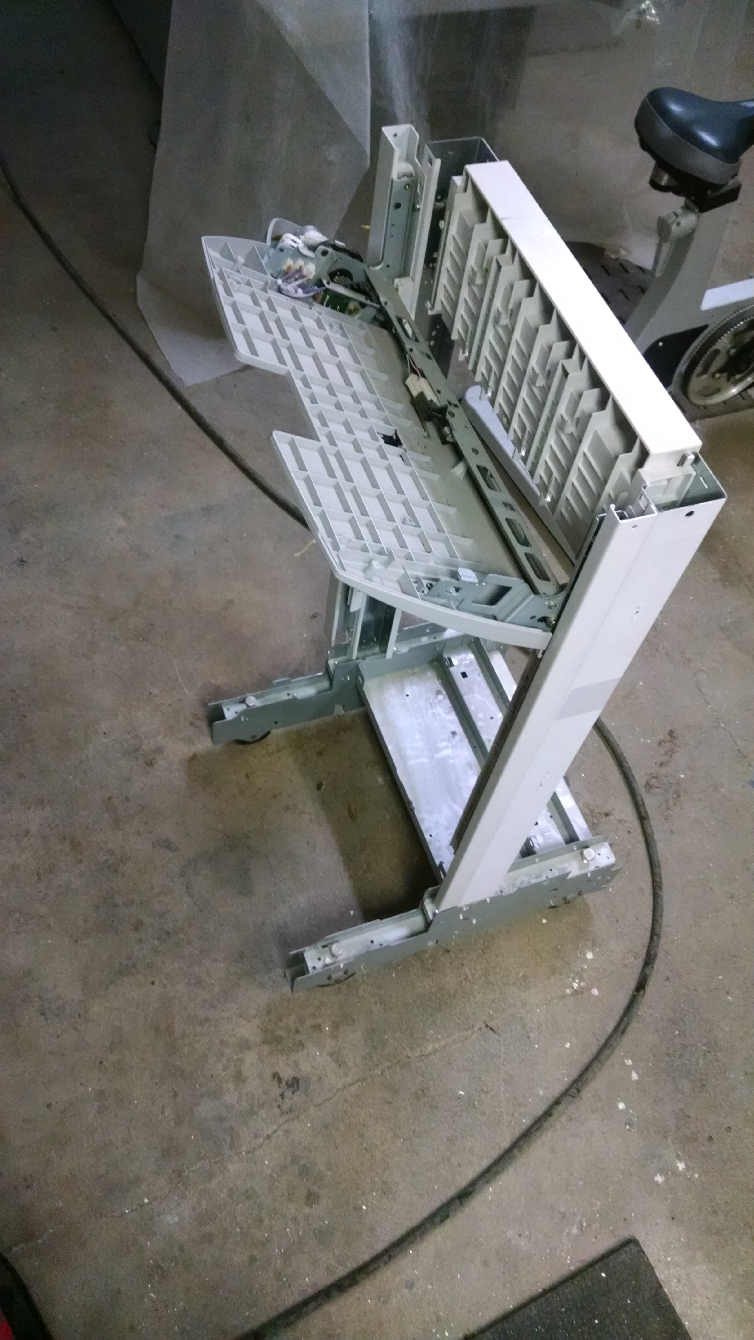
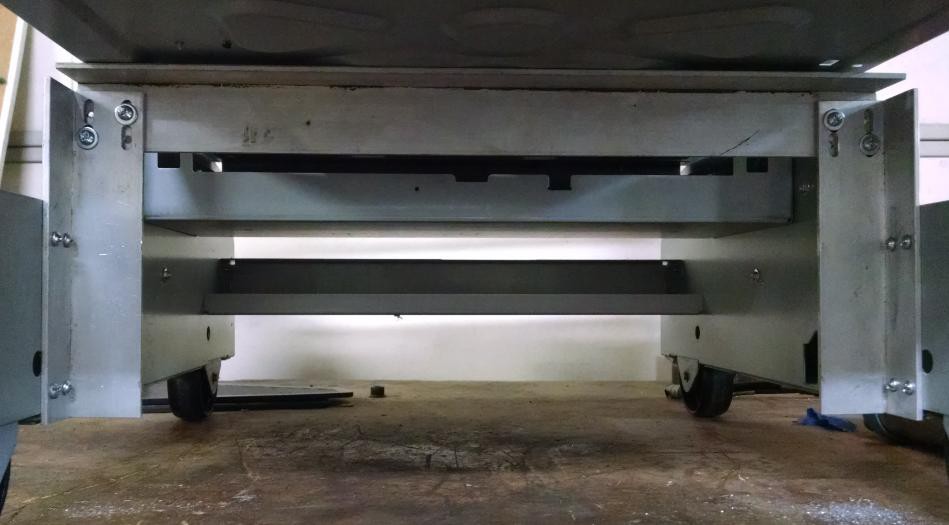
    And here is a 3/4 view of the completed Y axis mounting. In this picture, pay notice to the upright shafts that stick off of the bottom of the angles. These will eventually support the table.


  • Y Axis Carriage

    willbaden02/04/2015 at 11:33 0 comments

    The Y axis carriage is almost complete. It still needs a spring loaded bearing to contain it from side to side, possibly add a dowel or shouldered 6-32 screw to allow for a smoother guide for the up/down containment bearing shaft, and to test the new cable layout. Here is a quick overview of what I have:

  • Y Axis Mechanical Test

    willbaden01/31/2015 at 11:41 2 comments

    Before I could dedicate myself to using the selected scanner bed for the Y axis, I wanted to verify that the motor and mechanism was going to work. Here is a test of the Y axis.

    This proved it out, now to change the layout of the bed. Currently the bed can flop around up and down and slide for side to side perpendicular to the axis movement. This should be able to be remedied by using bearings on the top and the bottom of the bearing track to capture any vertical movement. And also adding bearings to press up against the side walls to prevent side to side movement.

View all 11 project logs

Enjoy this project?

Share

Discussions

Similar Projects

Does this project spark your interest?

Become a member to follow this project and never miss any updates