 willbaden
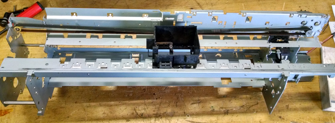
Moving on to the X Axis. This axis will use the same printer/mechanism that was used for the claw machine build. It did start with the intentions of using the complete assembly, but later morphed into using only the carriage, belt, and motor combination. This is how the axis began life:
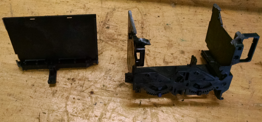
The carriage will still be used and was modified to allow for an aluminum angle to be mounted to it. The carriage (printer head) had the cartridge holder removed. This was done with a hack saw.
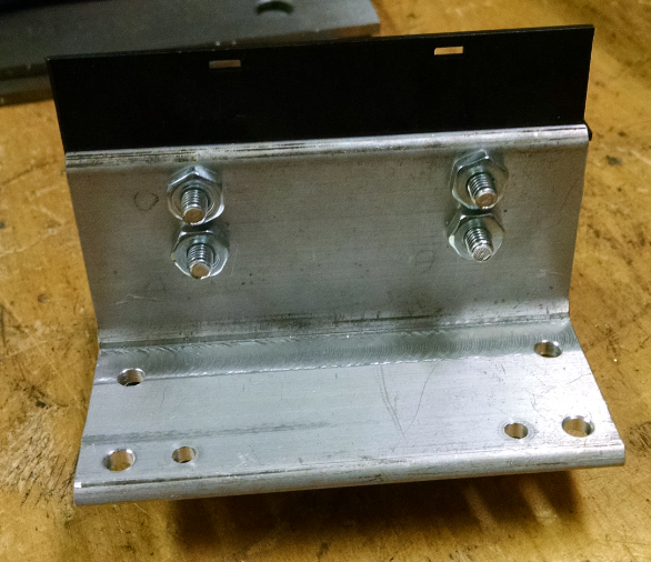
The leftover material from the cut was then milled down. This allowed an aluminum bracket to be mounted to it. The picture below shows the first location of the angle. This will have to be moved in the final assembly.
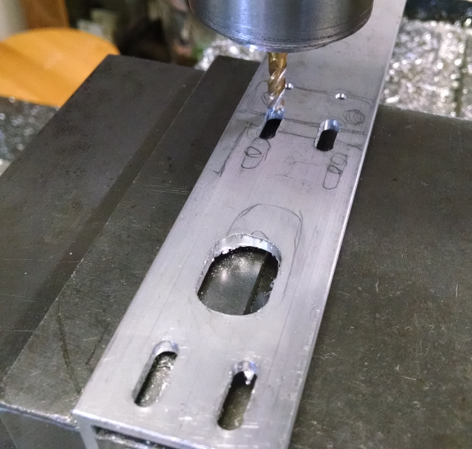
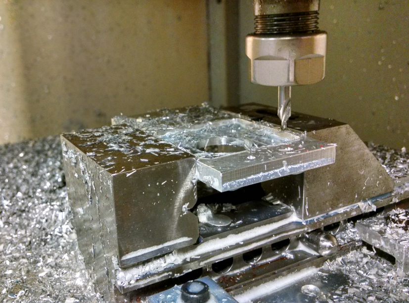
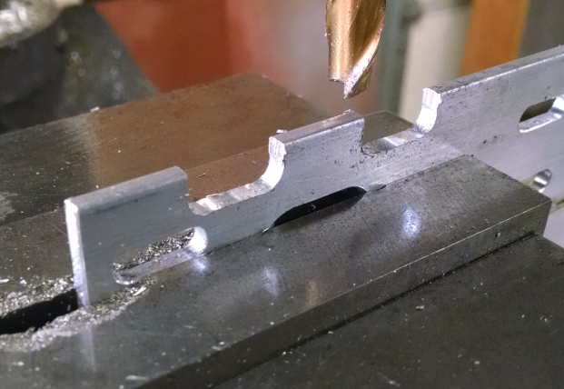
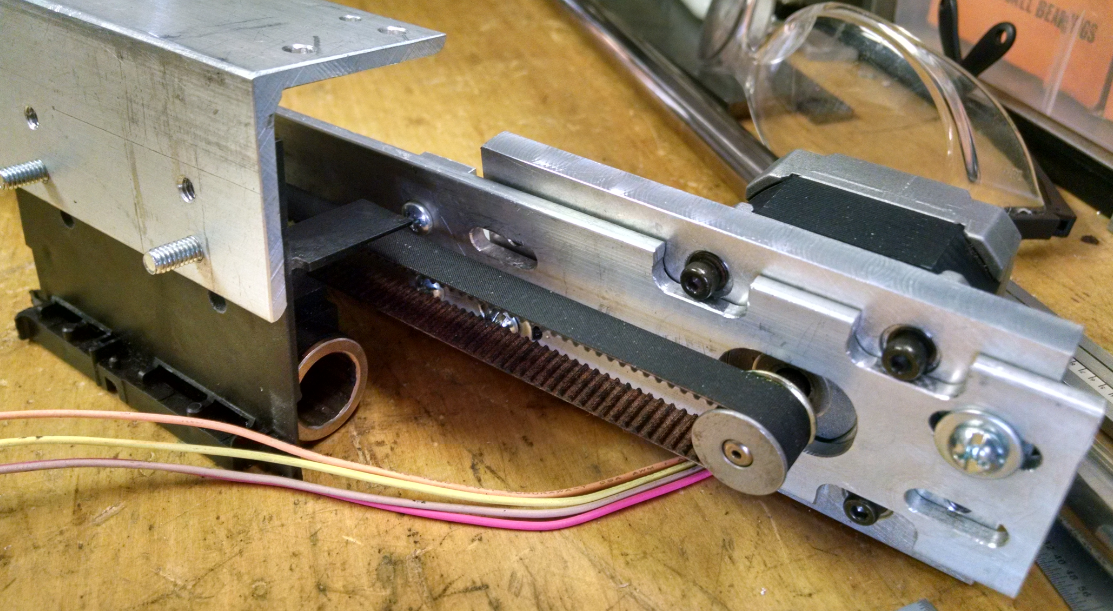
There will be a motor mount attached to one side of the angle. To aide belt tension adjustment, the motor mount fasteners holes were slotted. Further back from the end mill below are a couple of center drilled holes that will be used for the belt tensioner block.
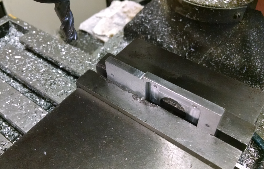
To allow for the motor pulley to sit in the center of the angle (top to bottom), the motor mount had a notch machined into the side.
 The screws that mount the stepper motor to the stepper mount required the aluminum angle to have slots for relief. First, holes were drilled out.
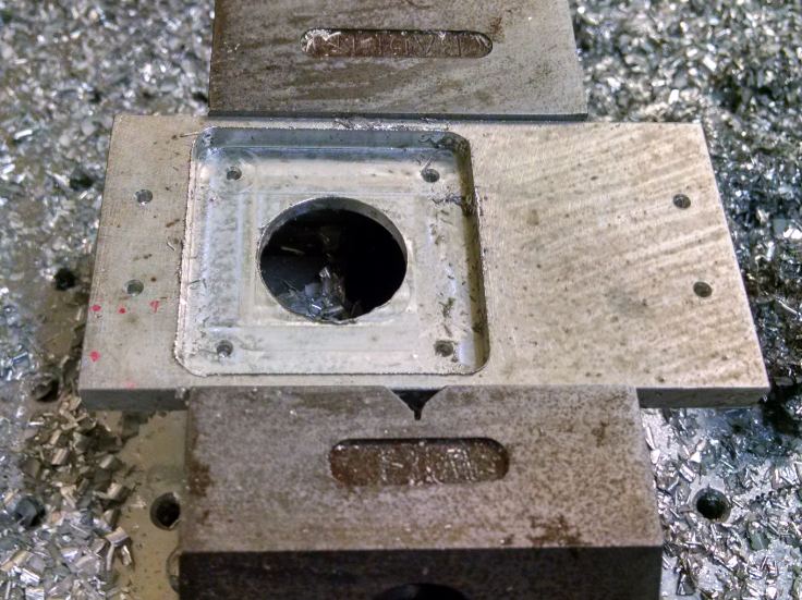
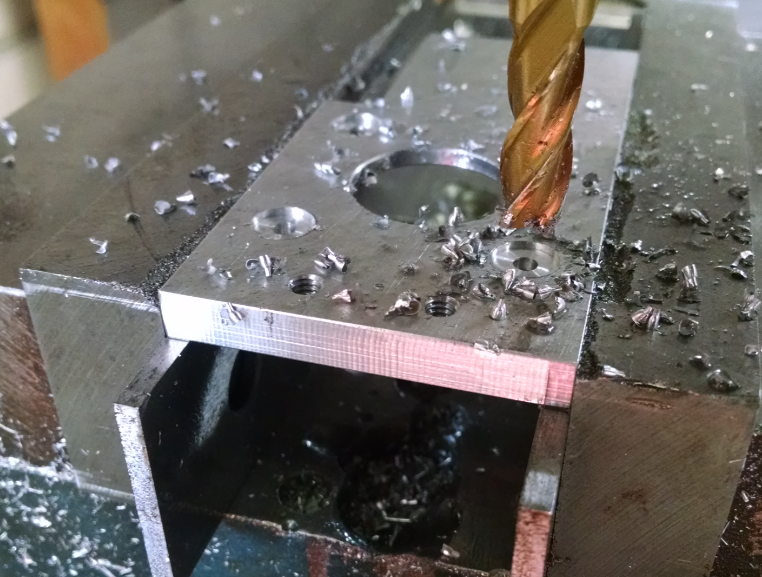
 The motor mount also required relief for the fastener washers. Using an end mill the counterbores were machined.
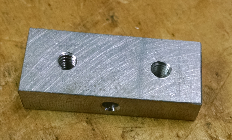
 Using a small piece of aluminum, the belt tensioner was machined. This had a cross hole drilled and tapped.
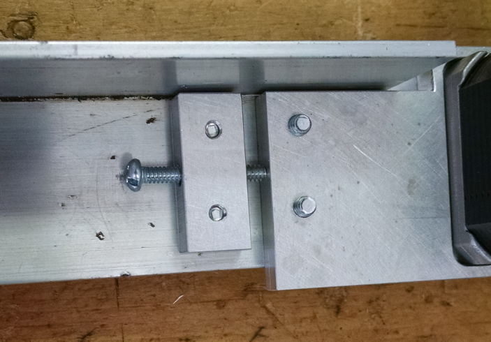 The assembly was mocked up for fit. Note that the aluminum angle attached to the carriage is now mounted differently. This will allow a place to mount the upper bearings of the X axis.
 The upper aluminum bracket was then machined to length. It will be used to hold the upper steel shaft.
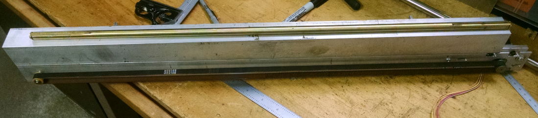
The steel shaft had 3 flats milled with one drill and tapped hole in the center of each.
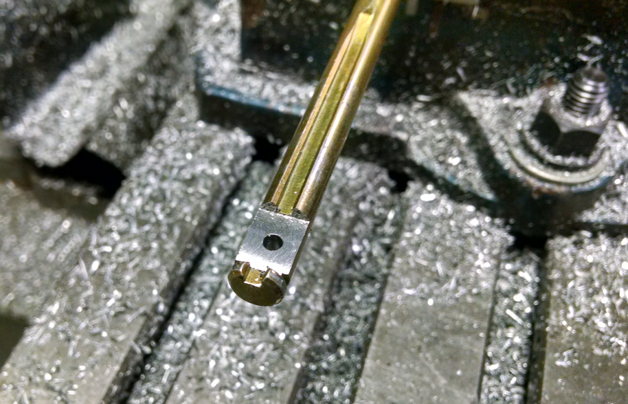 These flats accepted aluminum spacers that allow for only 3 points of contact for the shaft.
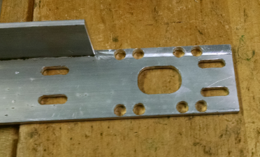
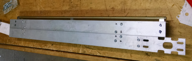
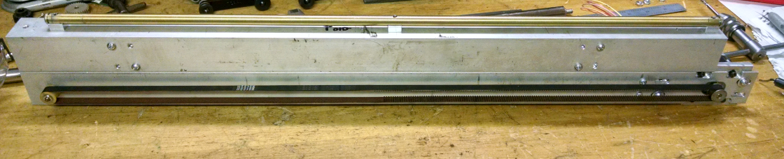 The upper and lower angles are mounted together using 2 shorter lengths of angle fastened with 8 screws per angle. They will be the center holes in the picture below.
 The next step is to make the brackets hat hold onto the lower shaft.
Discussions
Become a Hackaday.io Member
Create an account to leave a comment. Already have an account? Log In.