Hardware Hacking of Accu-Chek Performa Insight
There is a great insulin pump Accu-Chek Insight for Type 1 Diabetes patients. It has a remote control called Accu-Chek Performa Insight communicating with the pump via bluetooth. But still there is no smartphone application available today. So let's go make some steps towards it and make some hardware hacking today!
1. Disassembling
When you open the remote control up and unscrew some tiny torx screws, you can notice some basic things:
- There is a 3.7V Li-Ion battery, so we can guess that operating voltage might be standard 3.3V
- There is a Windows CE 6.0 label informing us about used operating system
Further we can scan all big chips on the board and search for their datasheets. The most important are these:
- iMX233 - the heart of the device (SoC)
- NW164 - NAND flash (at least 512MB)
- 2 x D9LQQ - RAM modules
- 24A1025I - some EEPROM (128KB)
- 564RK - some other EEPROM (64KB)
Windows CE 6.0 + remote control firmware won't fit on SoC either on both EEPROMs, let's assume it's located inside the NAND flash, so NAND flash will be our primary target. But how to dump it easily ? The first option is to try careful unsoldering and reading it on some memory reader, but that's a quite expensive and risky way. And even if it succeeded the data might be encrypted by some unrecoverable key. The next option is to try some hardware debugging using JTAG which is easier way and that's why we are going to give it a chance first.
2. Getting the right equipment
Studying the iMX233's datasheet there is a chance that SJTAG (serial JTAG) will be used, so we must get prepared well. We'll be using this hardware tools:
- Some basic digital multimeter with voltmeter and ohmmeter
- Mini Saleae 16 Logic Analyzer USB (100M max sample rate)
- Olimex ARM-USB-TINY-H (hardware JTAG debugger connected by USB 2.0)
- Olimex iMX233-SJTAG (SJTAG to JTAG adapter specialized for iMX233 chips)
- Bus Pirate v3.6 or similar (for capturing possible UART communication)
We will need some software as well, so let's get
- OpenOCD 0.10.0 (for JTAG debugging)
- putty (for telnet and serial terminal sessions)
- Nkbintools (for extracting files from dumped ROM image)
- ILSpy (for reverse engineering extracted binaries)
3. Some basic findings
Our remote control is slightly disassembled (without battery and back cover) but it can still be powered on by USB charging port so let's do it. Remote is operating normally and that's fine. Now we can randomly measure voltage on many pins of the board and we get to maximum about +3.0V nearby the SoC. So it really looks like standard +3.3V and that's great because we will not probably need any voltage converters for our debugging hardware. So far so good so let's power it off again.
Looking at the board there are six greater pins than the others so let's concentrate on them and safely connect them to a breadboard. There is no need for soldering, six narrow wires and a small rubber band will do the work. One of the pins is quickly identified as GND (by using ohmmeter measurement). Now we can connect the remaining five pins to logic analyzer and start recording and powering the remote on again. Recording reveals that one another pin has some signal on it. Ok, it should be UART for example so now we connect it to Bus Pirate for example and set it up for UART communication (let's start with common baud rates 115200 or 9600). Bingo! We've got nice Windows CE bootloader log giving us some new clues.
These lines are most important:
INFO: Reading NK image from NAND (please wait)...
INFO: Loading image is 100% completed.
INFO: Loading of NK completed successfully.
INFO: Loading boot configuration from NAND
Download successful!  Jumping to image at 0x80200000 (physical 0x40200000)...
Now we know, that
- system image is definitely inside NAND flash
- during boot loading there is some image preparation (maybe decryption or just copying...

 Param Aggarwal
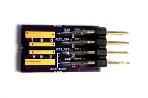
 ajlitt
 Ken Yap
Great work! There is open-source software (Sightremote) that allows driveing this pump but one needs service passwords to do so.
So... any chance of sharing thos service passwords? Maybe the're universal ;-)