 The Big One
The user interface is pretty simple:
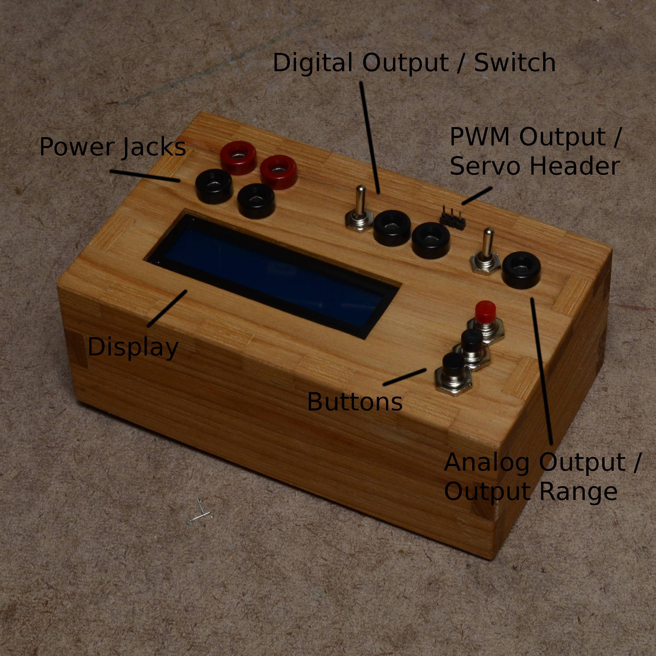
- There are four power jacks (to get the full range of +/- 5v output on the digital signal, you should run it with a dual supply of something between +/- 6v to +/- 12v). The second ground port allows you to chain to a breadboard in case your power supply does not have multiple ground ports (mine does not).
- There are three outputs: digital, PWM, and analog. The digital output is for the fast and slow square waves. The PWM output (and its accompanying servo header) are for the servo test mode (and eventually will be for the general PWM mode, when I get around to programming it). The analog output is for the various analog waveforms.
- There are two switches. The one beside the digital output enables or disables the opamp buffer for the digital signal. (At least with the op amp that I am using, you get a lot of slew if the frequency is faster than about 10kHz.) The switch beside the analog output changes the waveform range from 0 - 5v to -5 - 5v.
- The red button is 'Mode'. Use it to switch between the various waveform options. Hold it down to start waveform generation, and hold it down again to stop waveform generation. You cannot switch to another waveform while the current one is running.
- The other two buttons change the frequency up and down. Hold them down to go faster. You can change frequencies while the waveform is active, and the change takes effect immediately.
Discussions
Become a Hackaday.io Member
Create an account to leave a comment. Already have an account? Log In.