 HybridAir
DISCLAIMER: While this project is currently in an ever-changing state, the following details should be mostly accurate.
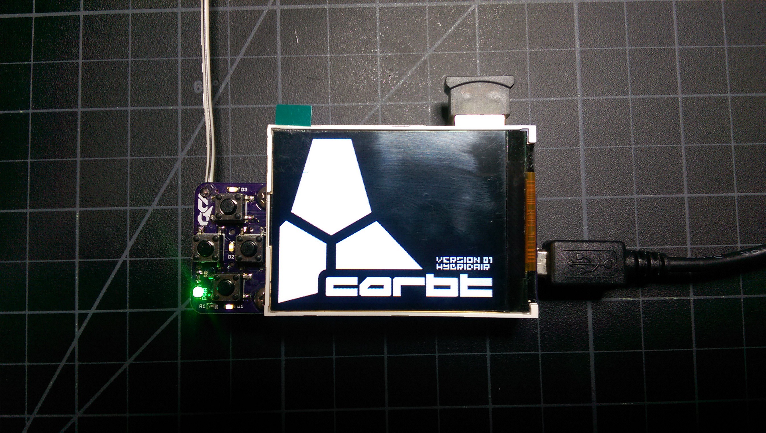
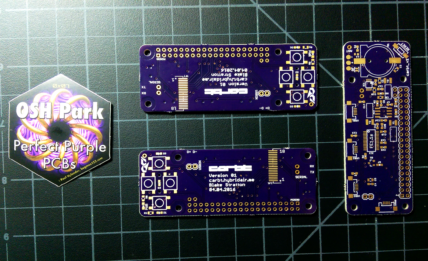
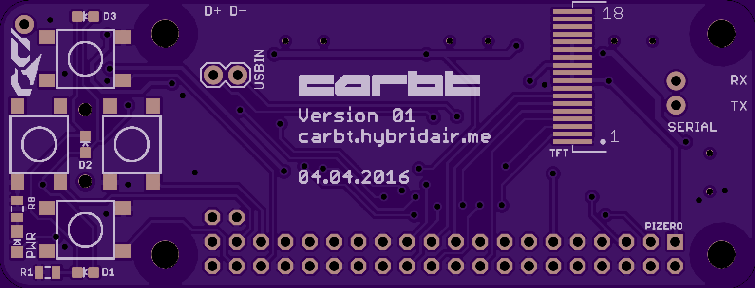
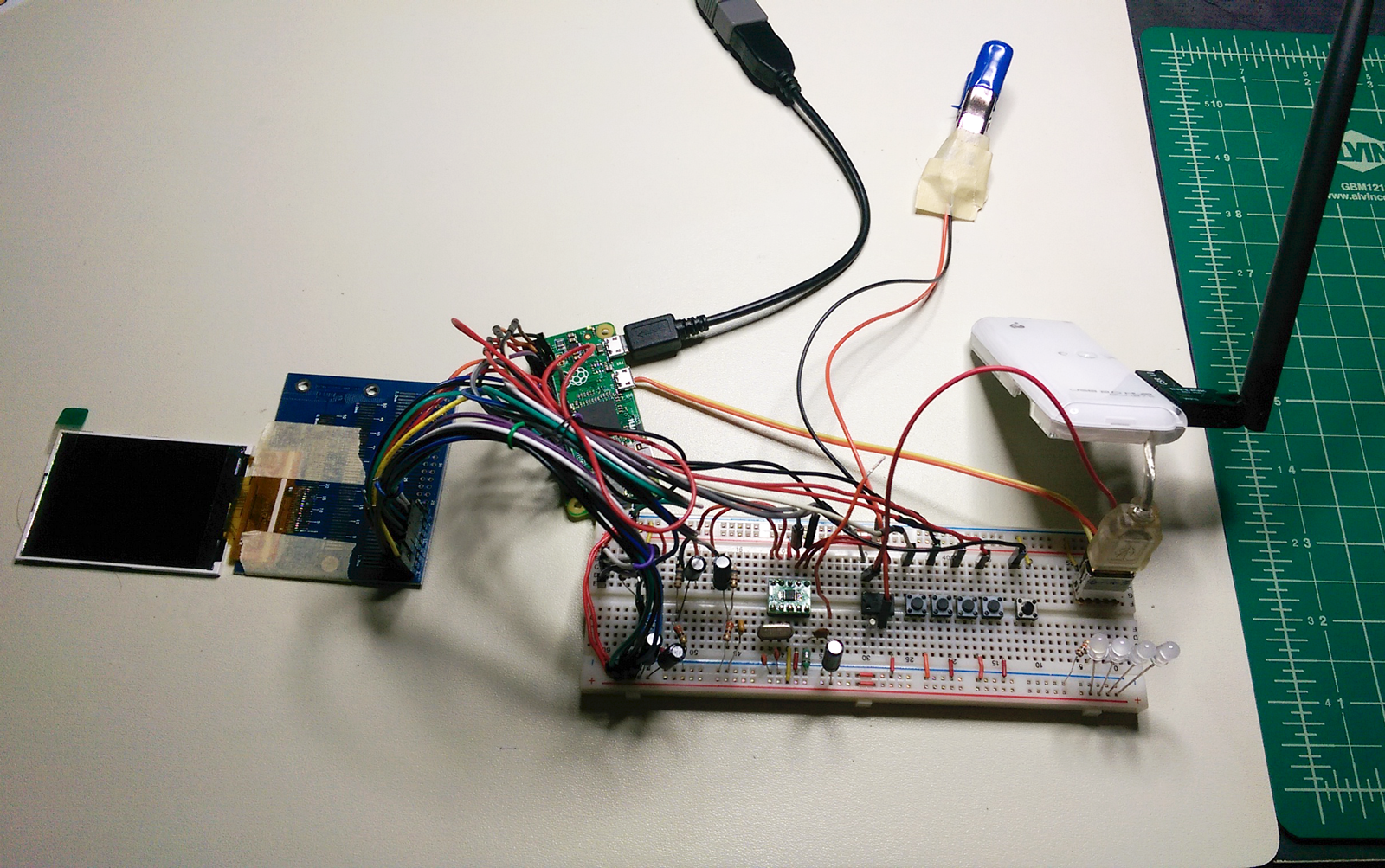
The carbt_v1 is the first ever iteration of my carbt project. This project's goal is to provide an inexpensive alternative to upgrading your car's stereo system, in order to easily play music from your phone in your car. The $5 Raspberry Pi Zero is the heart of the project.
Current features:
- Music sourcing and playback control from compliant devices over Bluetooth 4.0
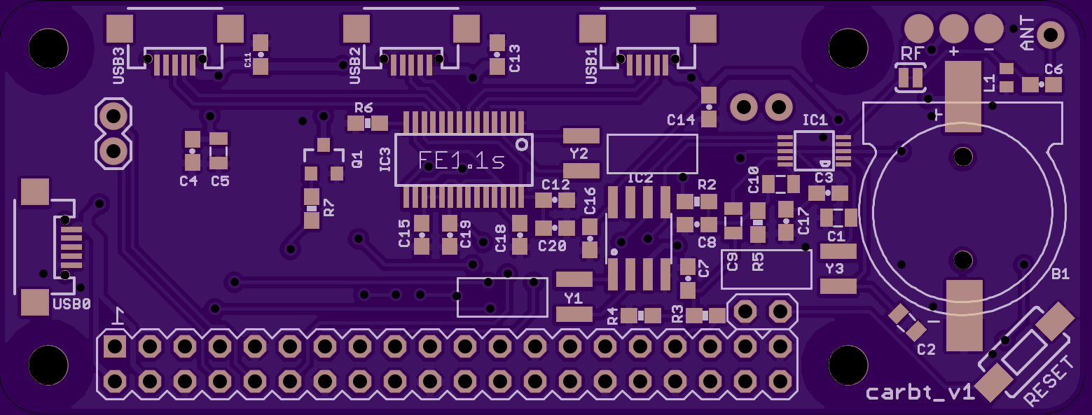
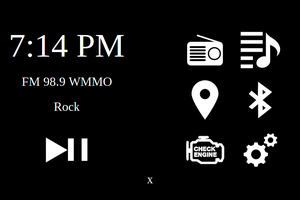
- Music playback wirelessly over FM radio
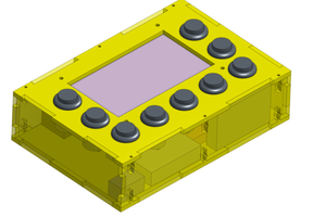
- TFT LCD for information display
- Bluetooth OBD2 adaptor support
- Powered entirely over USB
Planned features:
- OBD2 statistic logging
- 3.5 mm audio input and output alternatives to bluetooth and FM radio
- Onboard sensors like temperature or whatever maybe
- Custom USB device support (webcam used as a dashcam or timelapse camera, etc)

 Craig Hissett
 overflo
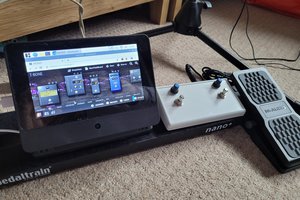
 pizzaMan5000
Hei, I love what you have done here. This transmitter look cool and I might to make one myself in the future. But right now I would like to try and make a simple fm transmitter with the QN8027 but I can't find any useful circut plans on the web. Could you help me with that? My goal is just to put two mics or an audio jack to the QN8027, an antenna, power supply and something to change frequencies. Do you have any schematics that could help me with that?