 Jared Sanson
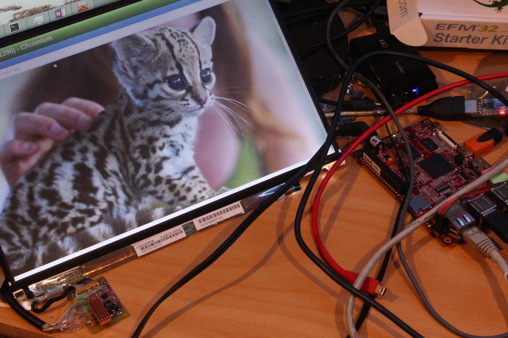
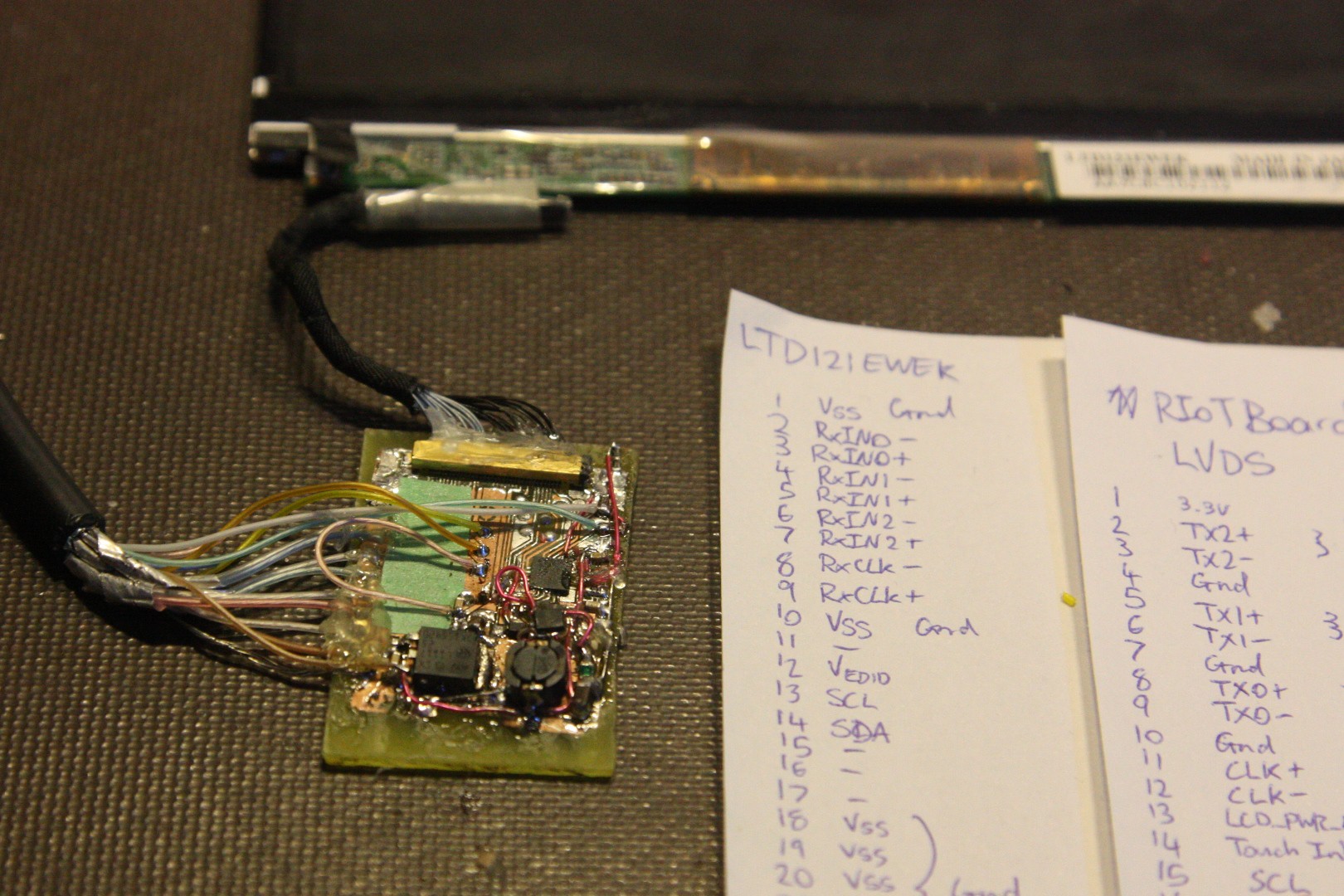
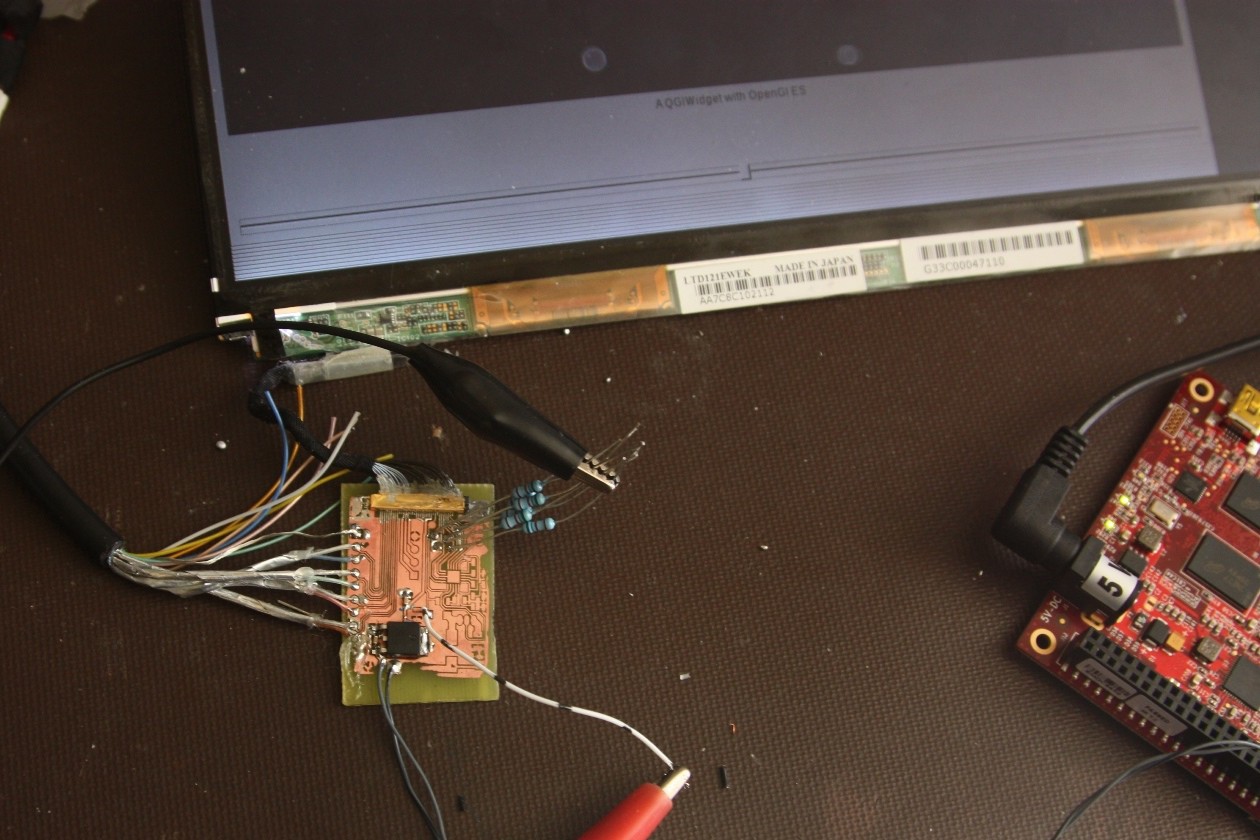
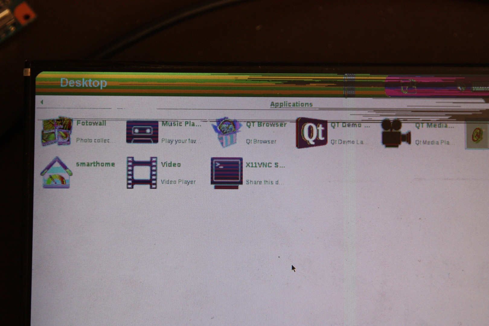
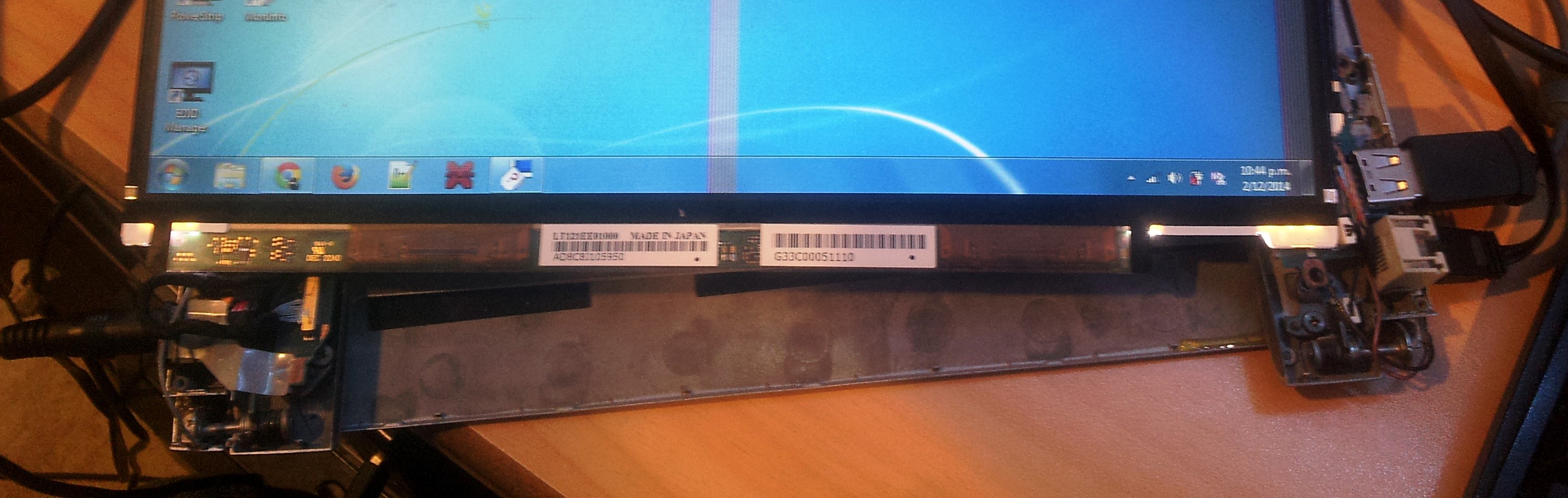
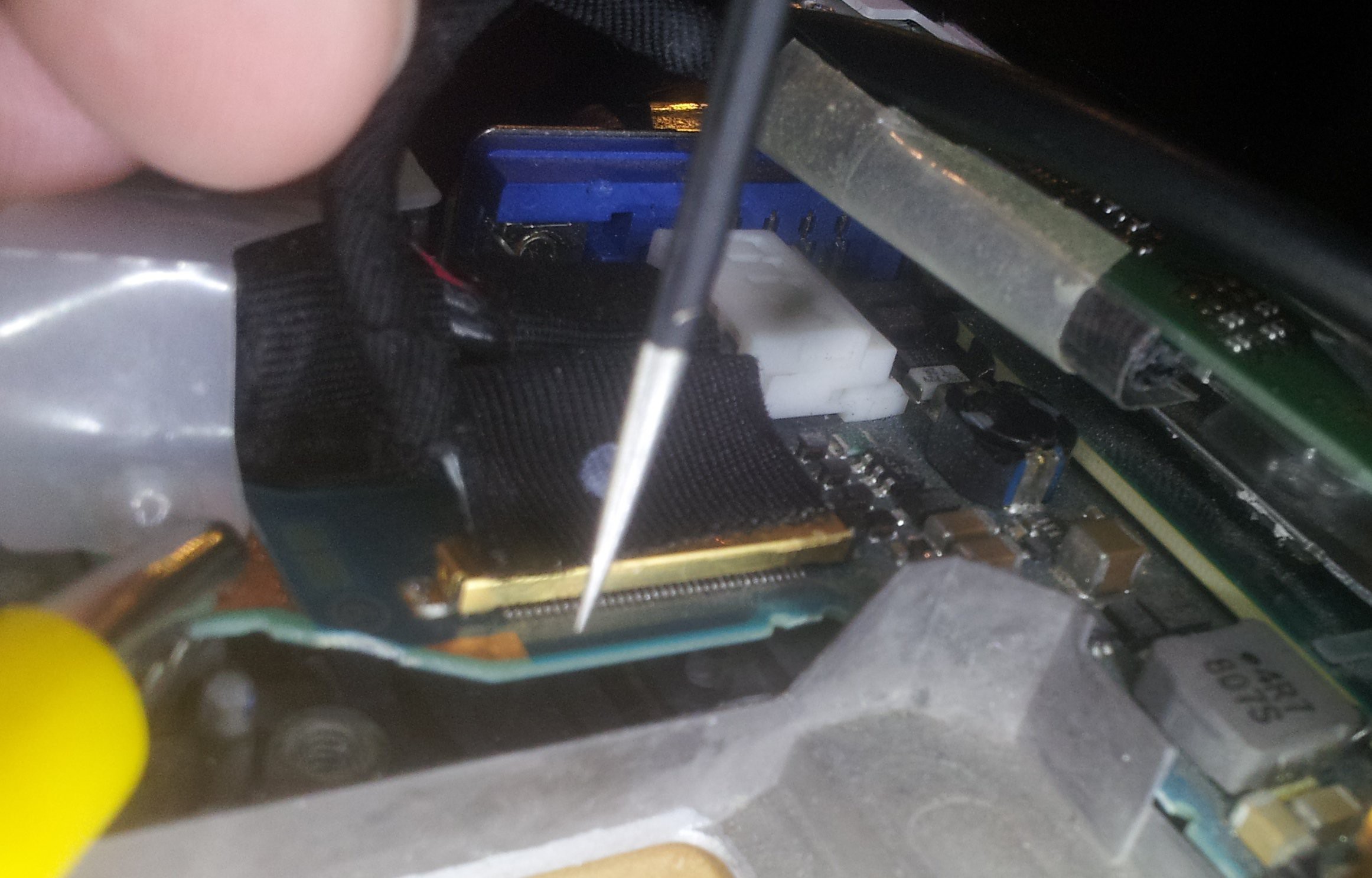
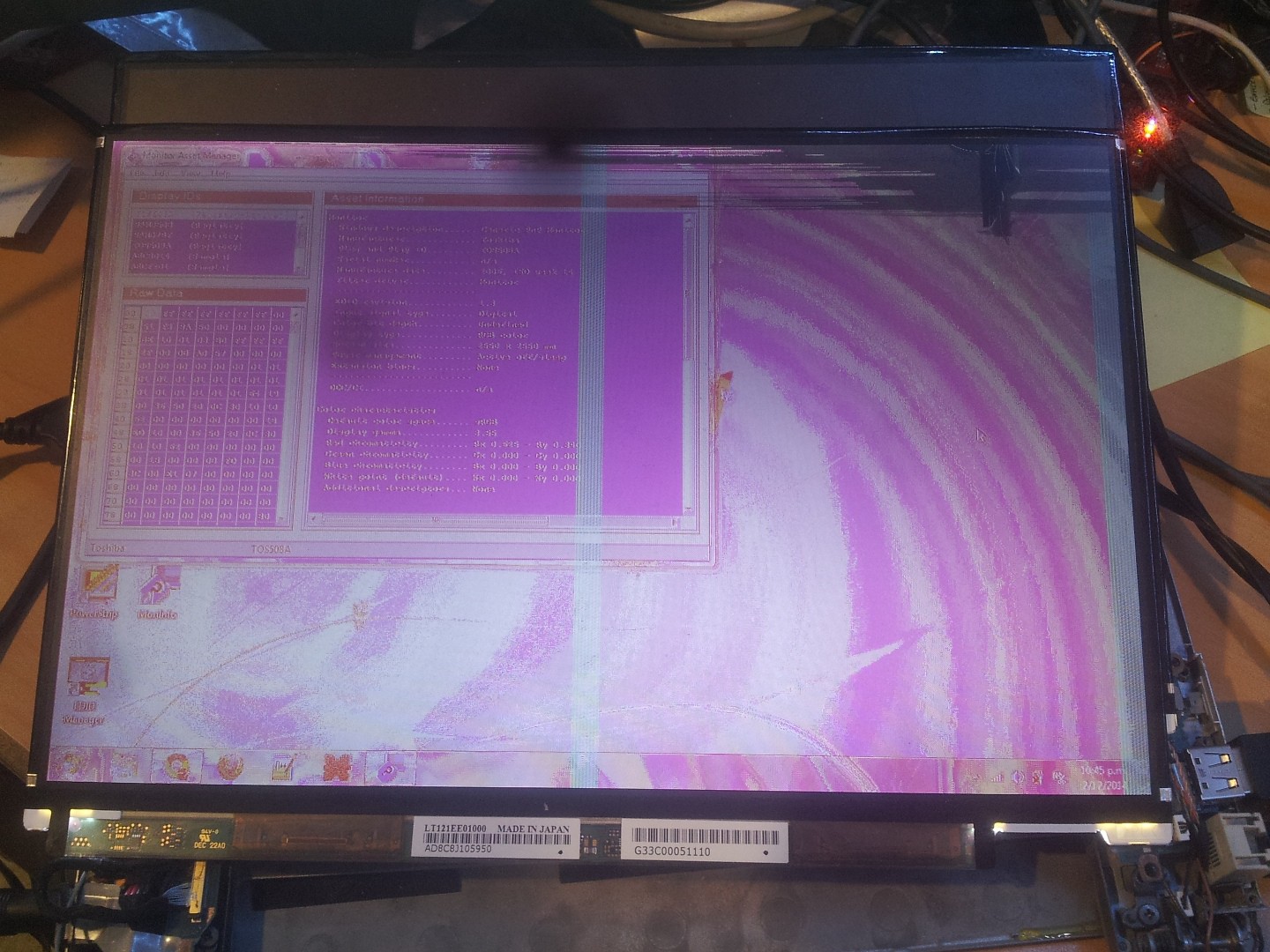
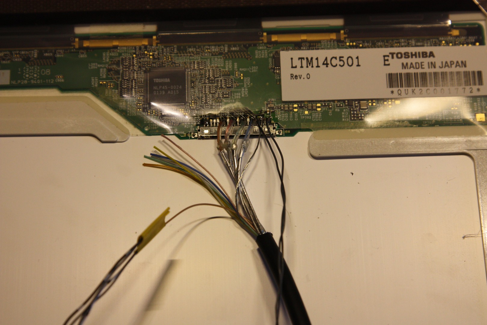
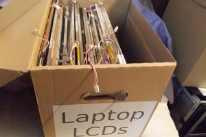
You might think that interfacing to a laptop LCD is not easily possible - laptop LCD panels do not provide an HDMI, DVI, or VGA interface, as they are intended to be wired directly into the laptop's graphics controller. However most laptop panels use the same interface: LVDS (Formally known as FPD-Link or FlatLink), and the protocol itself is very basic requiring no configuration of the panel, only requiring that the graphics controller is configured for the correct resolution!
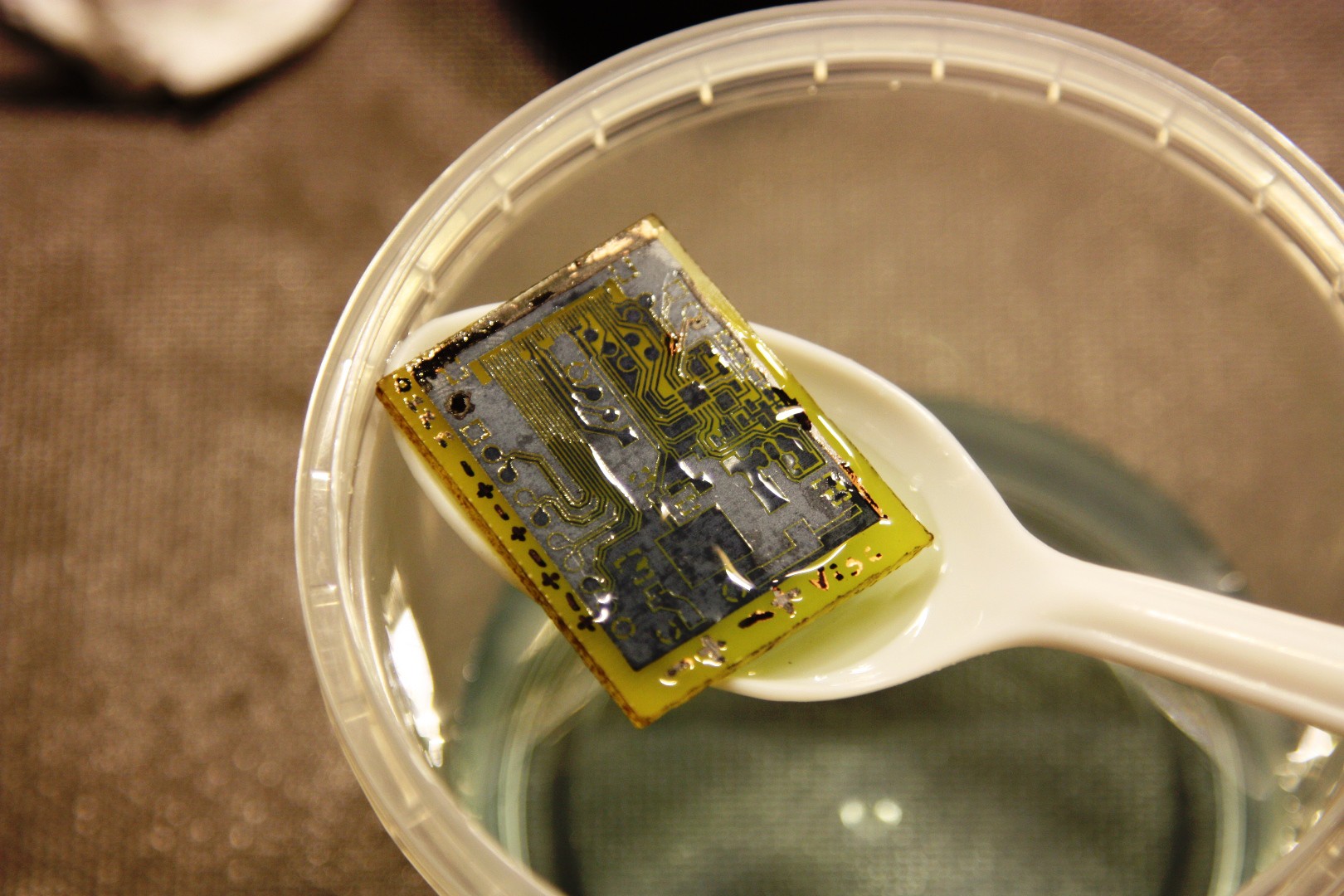
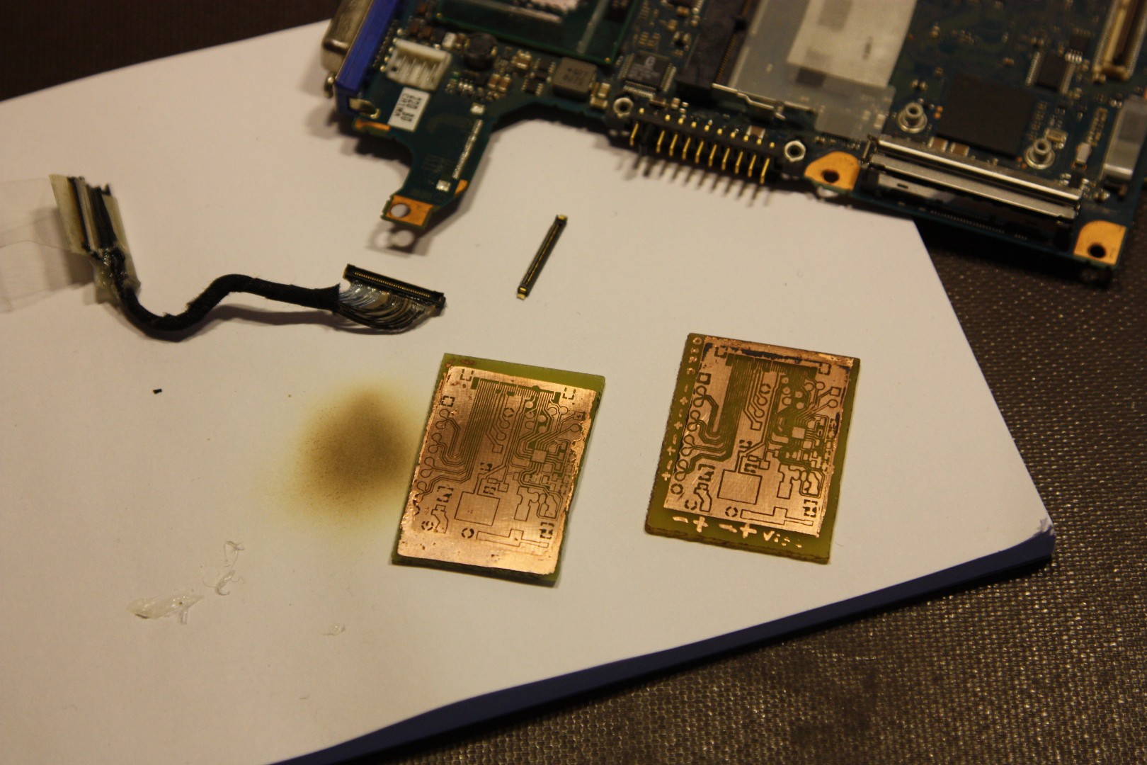
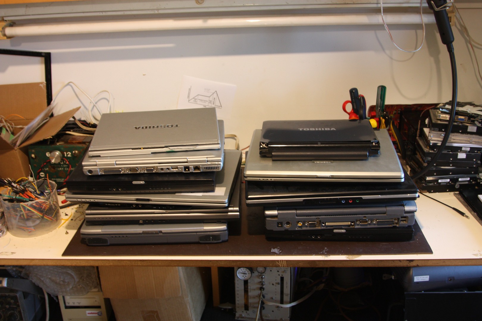
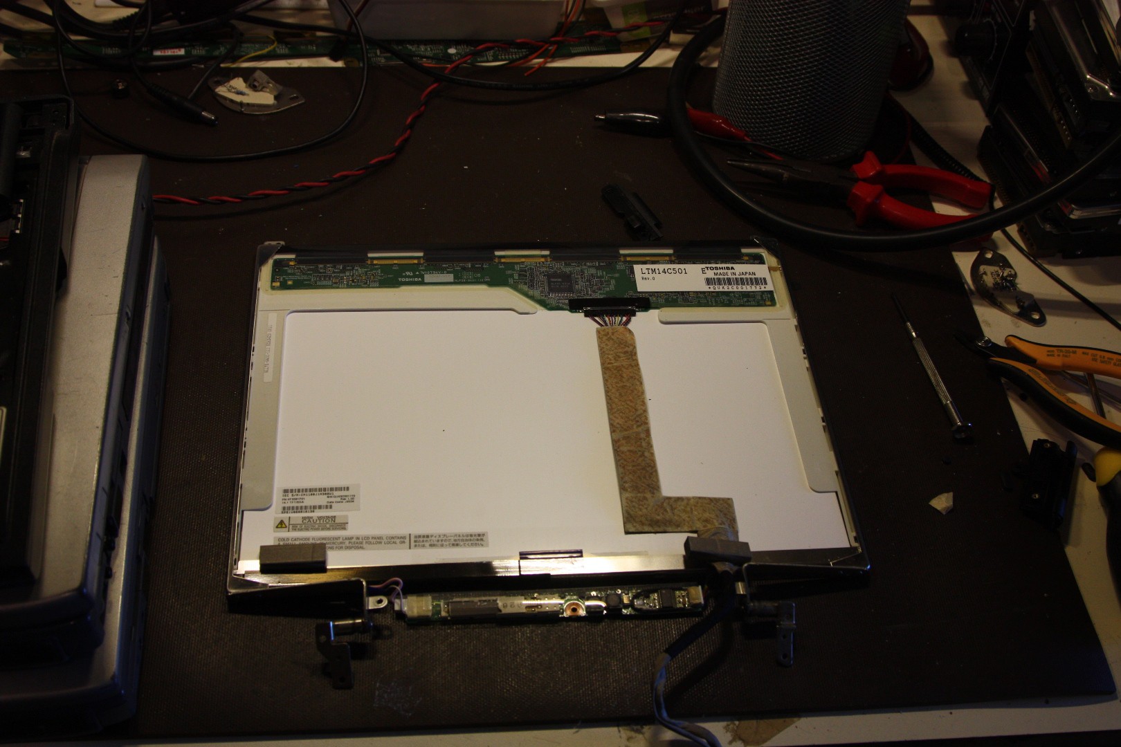
Here, I will document my experiments with various laptop LCD panels that I have.
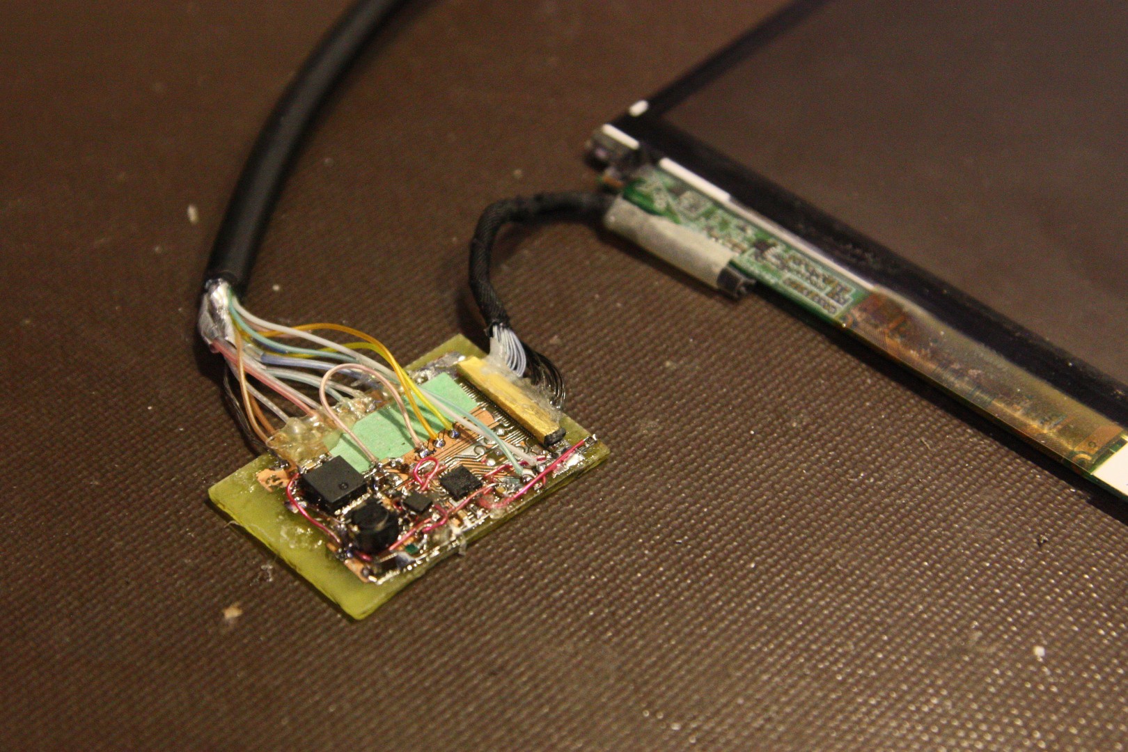
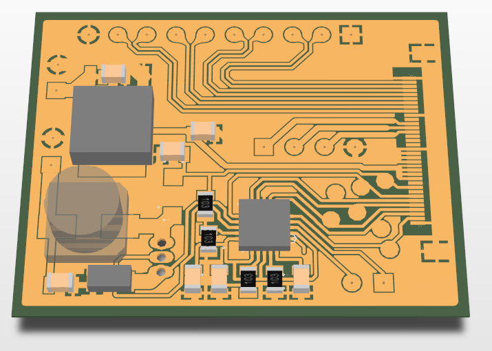
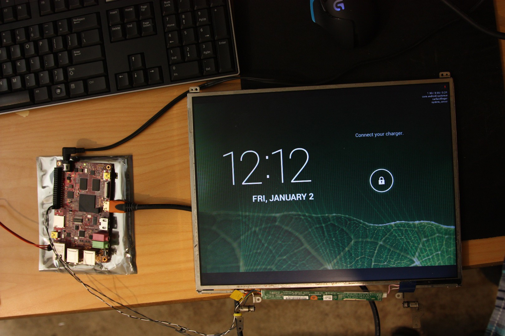
Instead of converting LVDS to a more usable protocol like HDMI/DVI, I am using a RIoT board which has a native LVDS connector, making it very easy to connect a panel!
Eventually I am thinking about writing an article documenting everything you need to know in order to re-purpose an old LCD panel. Let me know if you would be interested in this!


 Arya
Arya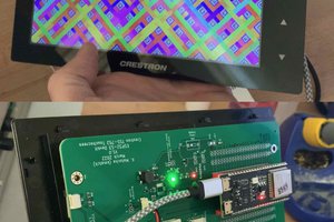
 kmatch98
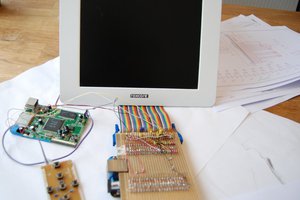
 charliex
Hello, do you know some device to register the signal going to laptop's screen or to check if it's right? On my old laptop Asus X55VD I had much eyestrain when using Linux, while it was ok with preinstalled Windows. The same occurs with my new Dell Inspiron 3559 (with preinstalled Linux Ubuntu). There must be some pulsation or dithering. Other people reported a similar problem, it prevents some people from using Linux.