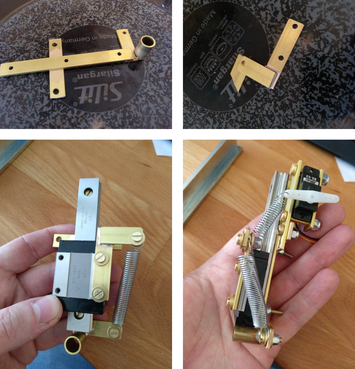
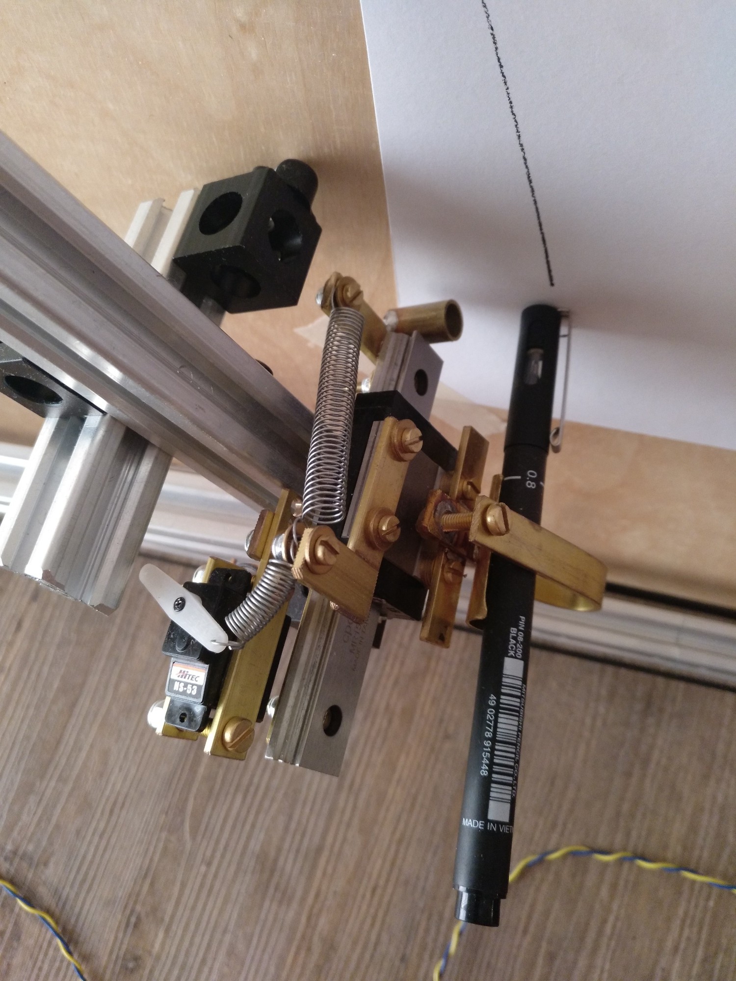
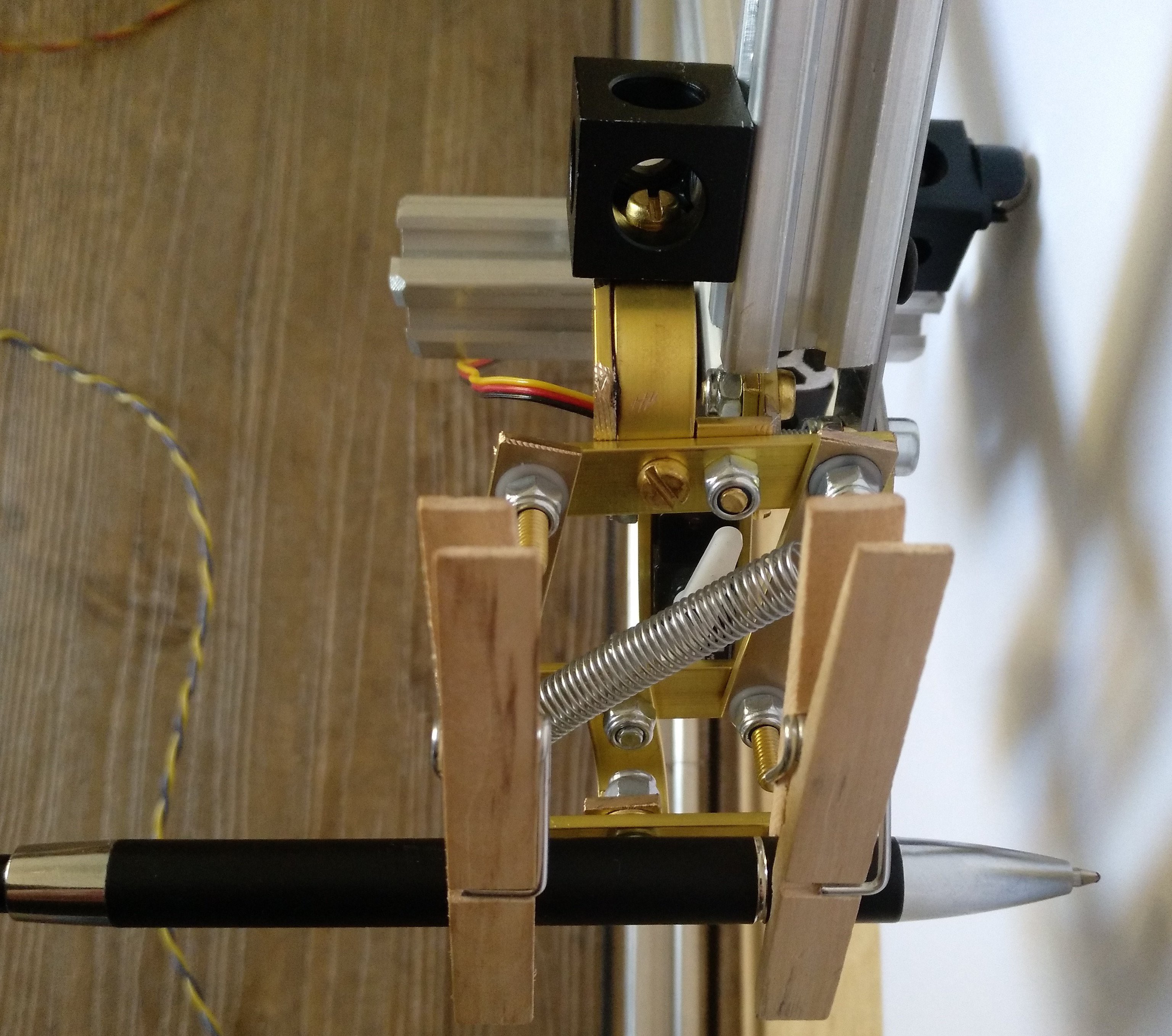
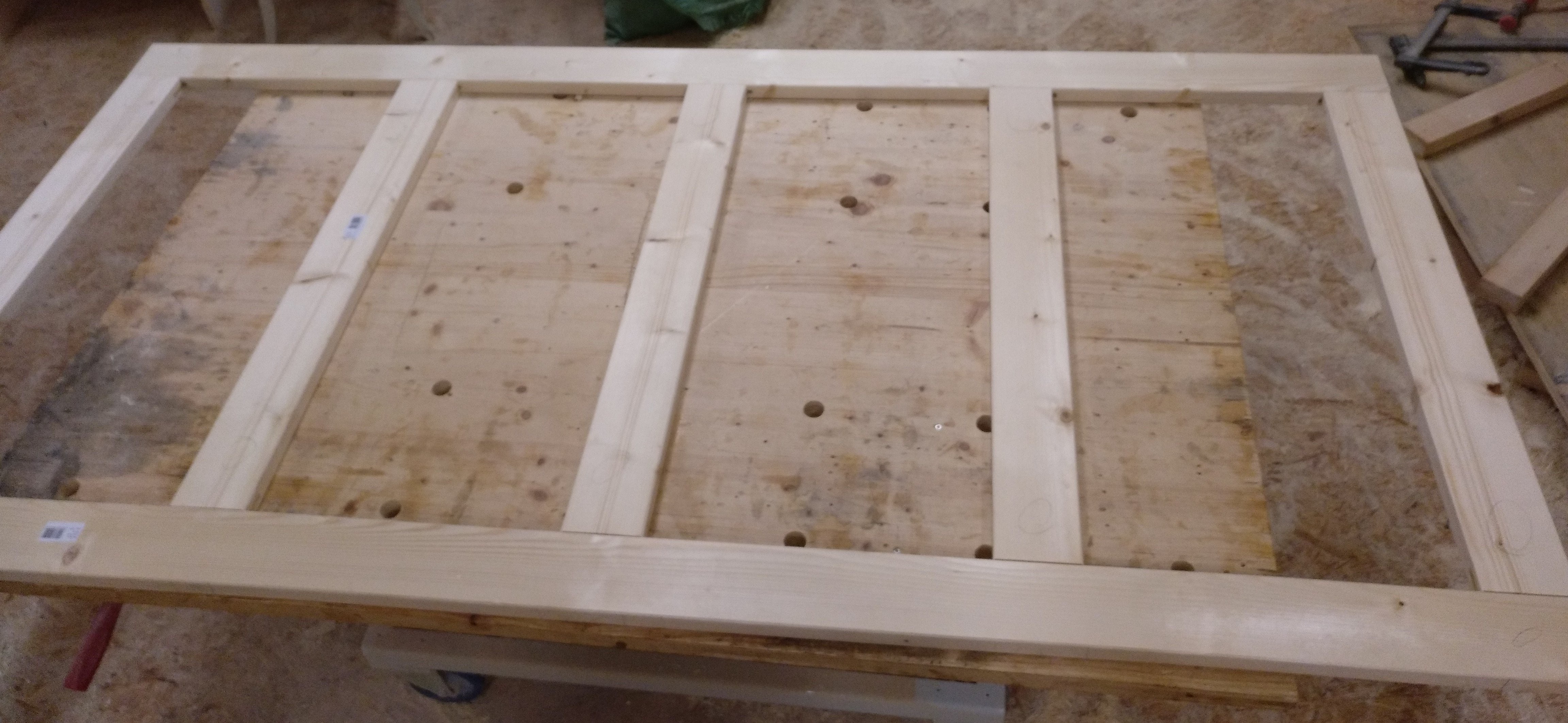
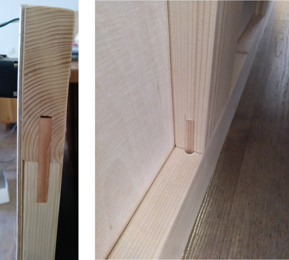
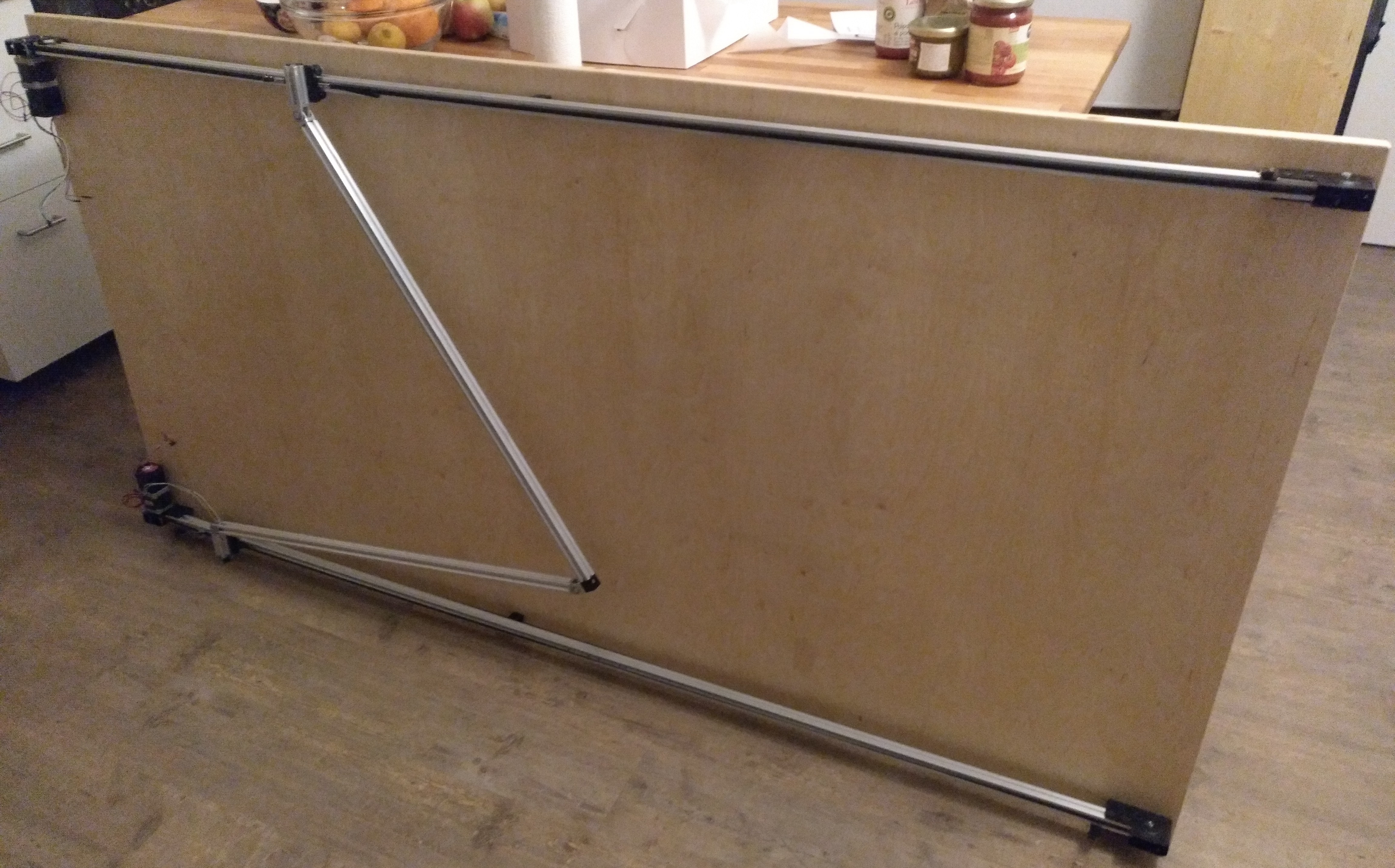
Close
0%
0%

plotbot

Plotting machine build to be hung from a wall. Uses a delta-arm design to save on parts and to improve elegance.

seisei
Similar projects worth following
I've got a big piece of wall in my apartment which is empty, and deciding what to put up there can be difficult (at least it is for me). The solution is to hang something there that is neither boring nor to blinky (first thought of LEDs but that would probably be annoying). The easiest way would be to just draw a picture myself or buy a good one but I can't draw and I usually waste my money on useless electronics so to kill two birds with one stone I had the idea to build a plotter which will paint me nice drawing directly while hanging on the wall..

The basic construction of the plotter consists of a thin wooden plate (3mm) which is glued onto a thicker wooden frame to increase the stability while being not too heavy.

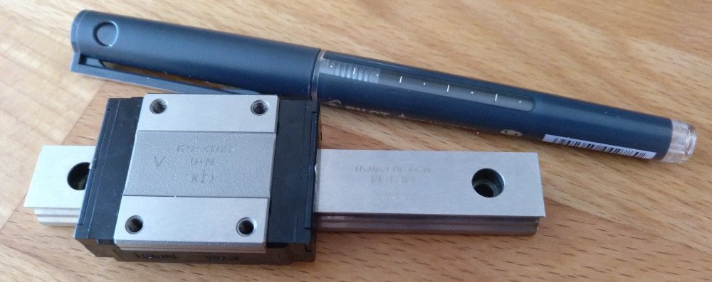
All the mechanic stuff is from http://openbuildspartstore.com/, it's not to expensive and even if it's IMHO not best quality it does a good job as far as I can judge. Also this saves on brain which is needed for the programming part.


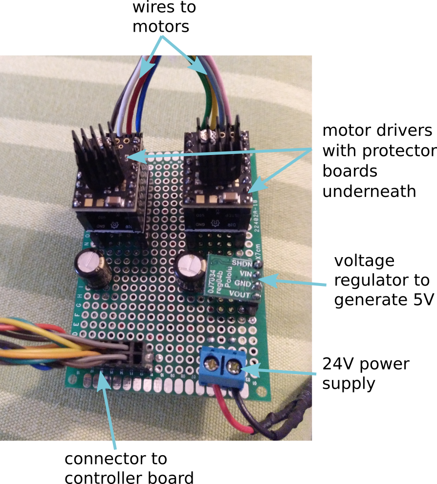
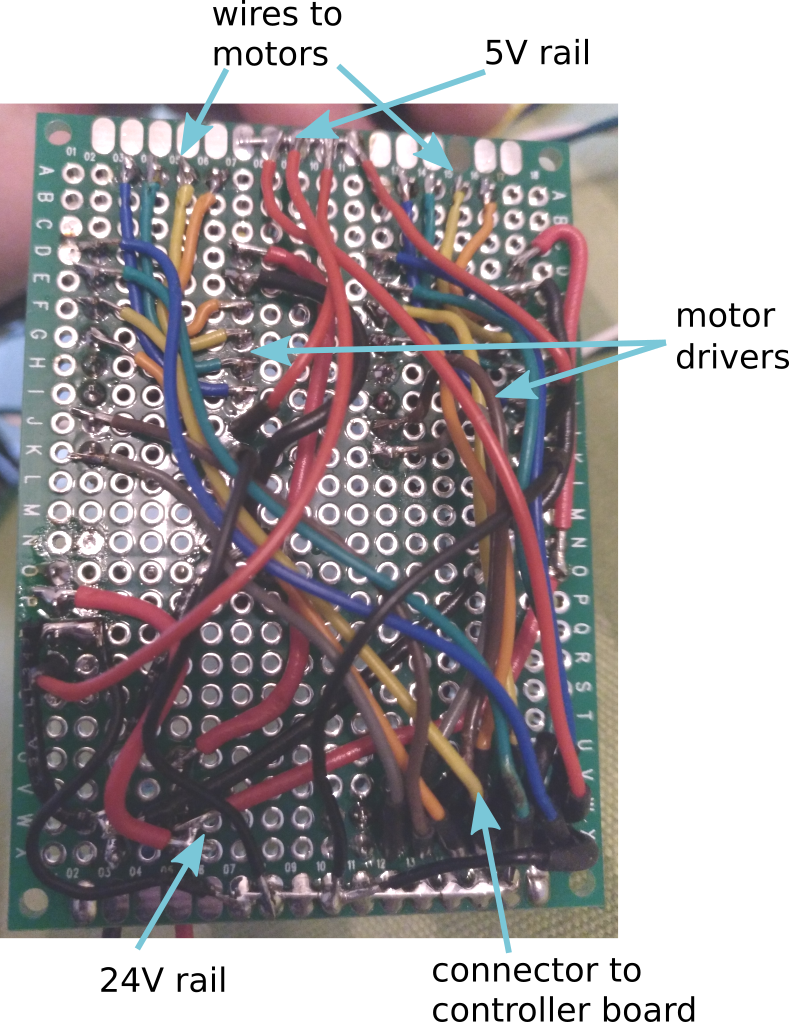
The electrics consist of a teensy and SilentStepStick TMC2209 drivers. I guess I'll need the raw power of the teensy because efficient programming is out of my league.

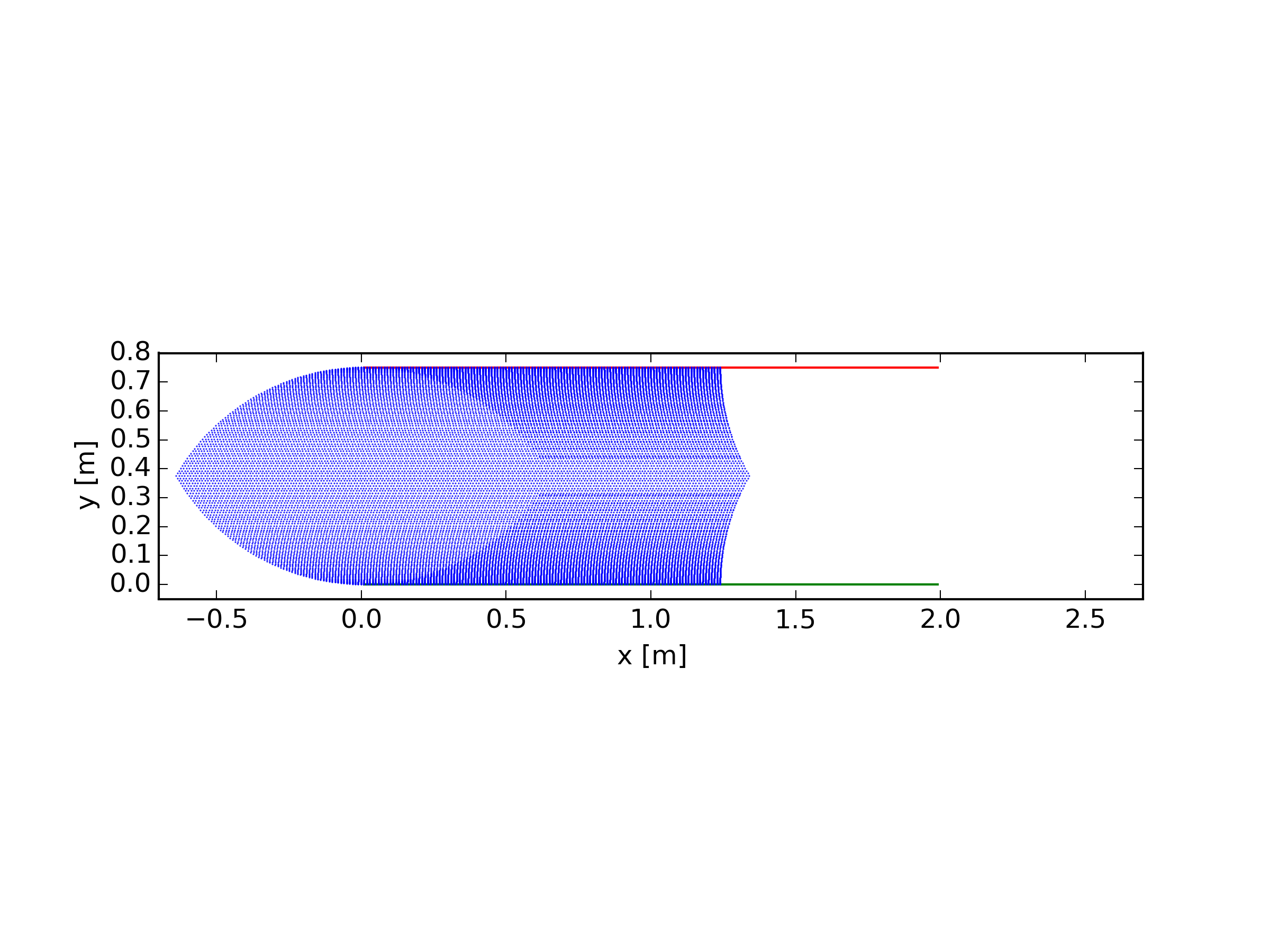
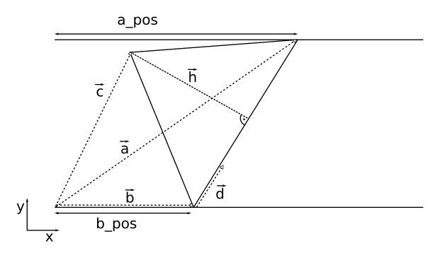
The initial alpha firmware can be found at github.


View all 20 components

  • Pen Holder v2

    sei05/28/2020 at 18:37 0 comments

    I got myself a nice little linear rail from smalltec.de for 50 bucks:

    This will now serve as the z-axis and also provide suspension so that the pen will have more or less constant pressure on the paper. The parts for attaching all the stuff were made from brass strips that I cut down to length, drilled and soldered together with a gas torch:


    The large soft spring is for giving the pen pressure on the paper while the small stronger spring is attached to a mini-servo for lifting the pen and was plasticly stretched to allow some movement upwards when the pen is on the paper.
    The finished assembly looks like this:

    It works great and is very stiff, so much in fact that I noticed how bendy the 1m long arms are, but nevertheless v2 is a big improvement.

  • Pen Holder v1

    sei04/04/2020 at 15:25 0 comments

    I made a simple pen holder out of brass strips, it is a parallelogram with plastic washers as bearings. A tension spring is used to ensure the pen has always contact with the paper, and a mini-servo is used to lift and lower the pen.

    While working okayish, unfortunately this design is very wobbly, so I'm making a version 2 based on miniature linear railing.

  • It has awakened

    sei03/21/2020 at 18:20 0 comments

    Motion demo of the plotbot is up and running, it filsl the buffers with timings that have a linear ramp (just a sawtooth-funtion) and moves the arms back and forth with varying speed. Timings for upper and lower stepper are phase-shifted by 180° so that they move in opposite directions. Now here's the video:

  • Firmware

    sei03/19/2020 at 19:52 0 comments

    Now that the basic firmware functionality is ready, I decided to make the github repo public, so feel free to take a look (if you are not afraid of ugly code).

    What works:

    • Homing
    • Jogging
    • Filling the buffers
    • Readout information (buffer size, position)
    • Make movements from the buffers (need to finish the demo code -> video incoming)
    • Basic gui


    If you want to try it on hardware, I advise you to just use free spinning motors, because any error in filling the buffers can cause the motors to spin indefinitely.

  • Electronics

    sei03/17/2020 at 17:37 0 comments

    I decided to pack the electronics on two different boards, one for the microcontroller and one for the motor drivers. Turns out this was a wise move, because I recently switched the motor drivers from A4988's to TMC2209's, specificly SilentStepSticks from Watterott and they are awesome! They are much quieter and I'm quite happy with the stepping speed they offer. I use them in conjunction with Protector Boards, because the power-on is a bit complicated without them.

    The controller board looks like this:

    There is one big connector to connect the microcontroller with the driver board, and several small connectors for the endswitches.

    The driver board looks like this:

    The motor drivers get fed by a 24V power supply. A voltage regular is used to generate 5V from the power supply and feed the driver logic and the teensy. The capacitors are necessary to smooth the voltage from the spikes generated by the motors.

  • Communication Concept

    sei03/16/2020 at 18:49 0 comments

    As I wrote in the description, I want to write as little code on the microcontroller as possible. Since I learned coding in Python, programming in C/C++ just feels tedious and I want to minimize it. So the idea was to do all complicated calculations in language that I like more, like Python or Nim (which is awesome!).

    As far as my understanding goes, usually gcode is sent to the microcontroller, which uses some variation of Bresenhams algorithm to calculate the timings for the stepper motors.

    My Idea is to instead calculate all the timings on the computer and send them to the microcontroller which stores them in a buffer and uses a timer to step the motors. For this, one needs fast serial connection and this is one reason why I chose to use a teensy for this project.

    The communication protocol for filling the buffer of the microcontroller with n timings looks like this:

    size

    function

    example/description

    byte
    command
    'b' , for filling the 'b'uffer
    byteaxis'a' , for the upper stepper
    float
    timing 0
    0.0001 seconds
    byteaction 0
    'd',  lowering the pen
    ......
    floattiming n0.0005 seconds
    byteaction n
    'u',  lifting the pen


    So there are two buffers, one for either stepper, that get filled independently. And the buffers hold the time in seconds until the next step should be done and some action that should be done at that point in time.

  • On coordinate transformations

    sei03/15/2020 at 15:20 0 comments

    The unusual geometry of plotbot means that one has to find a way to map the Cartesian coordinates of what shall be drawn to the coordinates of the steppers in a way that the tip of the triangle that is formed by the arms will follow the Cartesian coordinates of the drawing. In the first Log I made a python script that shows how to do that transformation if you want to go from stepper coordinates to drawing/tip coordinates. But to drive the steppers one has to calculate the transformation the other way around, which has given me some headaches but in the following I'll show how I solved that problem.

    First some definitions:

    • x and y denote coordinates in tip/drawing space, meaning x and y are the coordinates of a point in the plane of the drawing
    • a and b denote coordinates in stepper space, meaning that a and b are coordinates in a hypothetical plane which is defined by the steps of the stepper motors, but they can easily be expressed in tip space:

    With d being the distance between the rails.


    I could not  figure out how to go the reverse way from what I did in the first Log but there is another way to calculate the tip position from the stepper coordinates:


    So if we want to calculate the position of the tip we can simply calculate the position of the tip we can simply calculate the intersections of the the two circles centered at position (a, d) and (b, 0) with a radius that equals the length of the arms and choose the rightmost intersection as the solution.

    Now this is easily reversed:

    If we know the position of the tip (x,y) we can calculate the intersections of the circle centered at (x,y) with a radius that equals the length of the arms and the lines defined by the upper and lower rail. Now we choose the leftmost solutions and have our coordinates a and b, that define a point in stepper space (a,b).


    So that is pretty neat, but there is one more thing to know: These transformations are far from linear, that means they can't be reproduced just by a set of simple translations, rotations or a squeezing/unsqueezing of the length-scales.

    This haunted me while programming the control-software, and I will show the implications of this in a later log.

  • Still alive - Frame and Assembly update

    sei03/15/2020 at 13:40 0 comments

    Now that the Project has successfully ripened, it is time to make some progress!

    So I made a simple frame from wood (2.5cm x 9cm):

    The frame is just glued using simple tongue and groove joints:

    The grooves were cut with a router, and the tongues were cut with a band-saw. Then I just glued a 3mm three-layer-board on top.

    Next I assembled all the parts that gathered dust for the last years:

    The frame is 2m x 1m, which I realize now is a bit over the top, but you've got to give your megalomania a treat sometimes I guess.

    Right now I'm working on the software and I probably there will be more updates in the next weeks.

  • Calculation of usable area

    sei02/04/2015 at 21:16 2 comments

    To check if the geometry is ok I wrote a little python script to calculate the area which the plotter arms can acces:

    import math
    import matplotlib.pyplot as plt
    from matplotlib.patches import Rectangle
    from planar import Vec2
    
    al = 0.75 #arm length [m]
    f = 0.75 #position of rail a [m] 
    
    apos = [2 * x * 0.005 for x in range(1, 200)]
    bpos = [2 * x * 0.005 for x in range(1, 200)]
    
    cx = []
    cy = []
    
    for x_a in apos:
        for x_b in bpos:
            a = Vec2(x_a,f) # vector to position on arm a
            b = Vec2(x_b,0) # vector to position on arm b
    
            cl = (b-a).length #distance between a and b
    
            #calculate height of triangle which is spanned by the arms
            hl = 2*((al**2)*(al**2)+(al**2)*(cl**2)+(cl**2)*(al**2))-(al**4+al**4+cl**4)
    
            if hl > 0:
                # finish calculation of height
                hl = math.sqrt(hl)/(2*cl)
    
                #vector from a to b
                d = (b-a)
                d = d/d.length
    
                # turn d around by 90°, h points to tip of triangle
                h = Vec2(d.y,-d.x)
    
                # normalize h
                h = h/h.length
    
                # calculate distance to tip set as length of d
                d *= math.sqrt(al ** 2 - hl ** 2)
    
                # vector which points to the tip of the triangle
                c = a+d+h*hl
    
                #save coordinates of tip
                cx.append(c.x)
                cy.append(c.y)
    
    plt.plot([min(apos),max(apos)],[f,f],'r')
    plt.plot([min(bpos),max(bpos)],[0,0],'g')
    ax = plt.gca()
    
    points = plt.plot(cx,cy,'o')
    plt.setp(points,'color', 'b', 'marker', '.', 'markersize', 0.5)
    
    plt.axes().set_aspect('equal')
    
    plt.xlim([-0.7,2.7])
    plt.ylim([-0.05,0.8])
    plt.xlabel('x [m]')
    plt.ylabel('y [m]')
    plt.show()

    Running the script gives the following plot:

    The blue area is what the plotter can reach, the density of the dots is a measure for the resolution. Luckily the density is pretty homogenious, so the resolution of the plotter will be more or less constant over the whole drawin area.

    Also one might wonder what with the empty space on the right, I'll show that in a follow up.

    Here's also a little sketch which shows what the calculations in the script are based on:

View all 9 project logs

Enjoy this project?

Share

Discussions

Sven Jungclaus wrote 10/16/2016 at 14:11 point

you should have a look at this website...
https://www.blackstripes.nl/de/products/drawbot/BOTMK2/

  Are you sure? yes | no

sei wrote 03/15/2020 at 13:15 point

Hi Sven, thanks for tip! They have a really nice algorithm that I gotta check out.

  Are you sure? yes | no

Jarrett wrote 02/07/2015 at 01:05 point

Assuming you can travel the full length of the rails, wouldn't you get far more usable area by having shorter arms?

  Are you sure? yes | no

sei wrote 02/08/2015 at 18:38 point

There is always a tradeoff between height and width, for shorter arms
you will gain more width but also the accessible height will be
smaller. So far I couldn't think of any design that will beat a
cartesian bot/plotter when it comes to "spacial efficency". I choose the
length of the arms to be the same as the distance of the rails so that
the tip of the triangle will be able to reach from one rail to another.
This way I should be able to use a commercial paper format (75x100cm)
and fully cover it.
But there's also a little trick, it should be
possible to fold the arms in the other direction by letting the tip
point upwards and then moving the sledges as far form each other as
possible, this way the tip will fold inwards and now one can access the
space on the right side. So in principle one would be able to draw two
seperate pictures with this geometry. We'll see when the arms are up and
running if that works :)

  Are you sure? yes | no

Similar Projects

Does this project spark your interest?

Become a member to follow this project and never miss any updates