Smartphones include amazing technology. Unfortunately, a lot of it never gets exposed to users, mostly due to form factor considerations (my guess), and possibly due to “consumers don’t need it”.
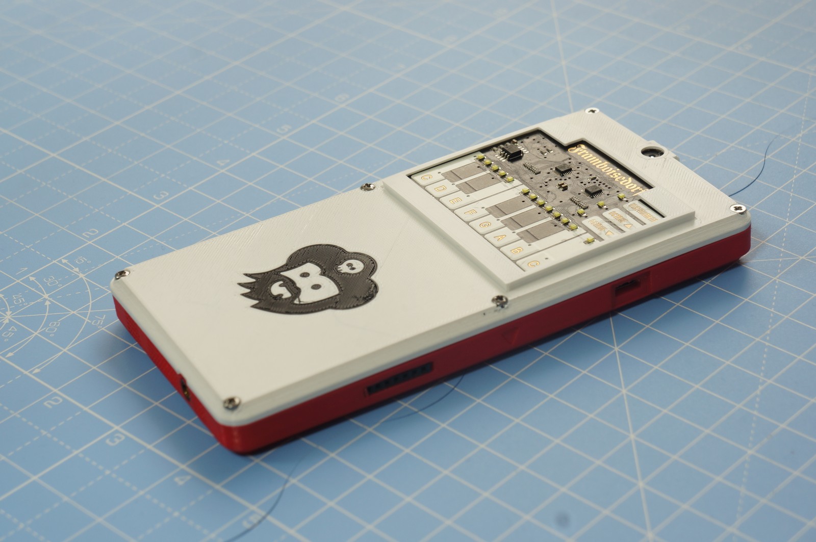
What do we have for this post? Let’s make some music with Kite… And not just any music – let’s make it LOUD. The speaker in Kite is fine for personal use, but that’s not something that showmen would fancy. To motivate you to read the rest of the post, here’s the PianoPhone:
For reference, the files required for this build are in piano-phone-v01.zip.
The centerpiece of the Piano Phone, is Pimoroni’s Piano HAT. This includes one octave implemented with capacitive buttons. It has LEDs for feedback - could possibly be used a learning aid too. Plus octave & instrument keys. To top it off – it’s a joy to behold.
Wiring this up is a bit more work than wiring up our name badge, though. Nothing too difficult. Let’s open the back cover & see for ourselves. Looks a bit of a mess, but hey we need quite a few wires. The Piano HAT is sensitive to exactly which wires you connect, though. At first try, we wired up the other 3.3V pin, which the Piano HAT just didn’t like. To cut a long story short, here is wiring:
That bit of tape ensures that we don't end up with accidental shorts. An essential safety mechanism...
The wiring looks a bit messier than what it is. Reason for that is I have cheated a bit & wired the I2S and power lines that we will need a bit later in this post (all the wires going over the pogo pins). I am documenting this at the end - after putting everything together - too lazy right now to tear up a beautifully built up unit for documentation.
Coming to the software : Kite runs Android, and that means that you need a tiny bit of effort to get Raspberry Pi HATs to work. Not too much work , mind you – but things may not work out of the box completely.
One of the things I like about the stuff from Pimoroni are their decent Python libraries. The chroot linux environment on Kite is the best way to get started (for a background on this, do have a look at the Name Badge post). The Piano HAT has two capacitive touch controller chips. The Piano-HAT library talks to it over I2C. The LEDs are connected to the same chips – making them very easy to control from the code. Each touch controller has an “Alert” GPIO associated with it. This is monitored by the python library.
Now, if there’s anything that Arduino has taught me (and the world) – it is this: interrupts are evil. Don’t do interrupts when… when you can just poll. The Piano-HAT library relies on RPi.GPIO, getting which to work with the same semantics on Kite would have been a serious pain; not something I was keen on. I wanted to make music, not war. So, I went to poll. I did. Luckily for me, Piano-HAT already had code to help me poll. Set the alert pin to -1 to unlock the magic. I wrote a silly wrapper for RPi.GPIO to ensure I don’t change code unless absolutely required. In case you are wondering what “poll” means in this context... it’s a while loop that executes in a separate thread, and periodically checks the capacitive touch sensing chips over I2C for events (checkout piano-phone-v01/kite-chroot-pianophone for all the gory details!)
--- a/Piano-HAT/library/pianohat.py
+++ b/Piano-HAT/library/pianohat.py
@@ -191,11 +191,11 @@ def setup():
         return True

     # Keys C, C#, D, D#, E, F, F# and G
-    _piano_ctog = cap1xxx.Cap1188(i2c_addr=0x28, alert_pin=4)
+    _piano_ctog = cap1xxx.Cap1188(i2c_addr=0x28) #, alert_pin=4)
     _setup_cap(_piano_ctog)

     # Keys G#, A, A#, B, C, Instrument, Octave -, Octave +
-    _piano_atoc = cap1xxx.Cap1188(i2c_addr=0x2b, alert_pin=27)
+    _piano_atoc = cap1xxx.Cap1188(i2c_addr=0x2b) #, alert_pin=27)
     _setup_cap(_piano_atoc)

     for x in range(0,8):
With this, I got simple-piano.py (in the Piano HAT codebase) to report the keystrokes. However, to get to this stage, I had spent a couple of hours. I was desperate for music. So, I thought: wouldn’t it be nice if Kite could just double up as a keystroke “server” of sorts? Tunnel the keystrokes to my Linux Laptop. Offload the music part on the Laptop… beats programming in Android Java for me any day.
I created piano-server.py (inside kite-chroot-pianophone) for this purpose. It starts a TCP socket server (port 1501), and reports the piano-strokes to a single connected TCP socket client. Then, using ADB forwarding, port 1501 of my Linux laptop is connected to port 1501 of my android device:
The second line starts the client - that connects to the piano-stroke server on port 1501 (code for simple-piano.py is in piano-phone-v01/laptop-client/, btw). Now, we can play some music:
With that bit of instant gratification out of the way, it was time for some serious work. Time to get rid of those wires. To make that happen, those key events need to go to Android – to the app domain. Java is good for network programming – wasn’t that how it became a smashing success in the first place? So, I fired up that Android Studio, and reluctantly started writing some Java code. Yeah, had to start doing some hard work, starting from io.kite.android.PackageNameWithCamelCaseAndAllImportsInOrderWithGoogleAsYourFriend
Okay Google, I give it to you – Android App programming is not so hard, and StackOverflow is my friend in my quest to make that simple sounding app. A couple of hours, and many crashes later, my app was ready. It was now able to make just the right noises when my fingers struggled to hit the right tune. So far, so good. The complete code of the app is available in android-app/SimplePiano in piano-phone-v01.zip.
The next problem? The small speaker on Kite is nice, but not something that I would use to announce to all my colleagues passing by – “here, it’s ready”. One of the nice things about the Raspberry Pi compatible header is that … it also gets me I2S audio. Route that over an amplifier to a big speaker, and get ready for some serious showtime. Luckily, I got just the right tools for this – an Adafruit MAX98357 I2S 3W Class D Amplifier, and that large 3W speaker from Google’s AIY Kit (PiMag subscriber, I am).
Android’s audio routing is a bit of a strange beast – again, it does what consumers want. And where exactly do consumers use I2S on a mobile phone? So sorry, no API for you. Hacks rule. I ended up changing the Android audio routing policy file to get my speakers blaring. Basically, we need to change /system/etc/mixer_paths.xml - with an important change, highlighted below:
The final part of the Piano Phone consisted of modifying the case so that everything sits nicely and looks like a phone. That took some work, but was immensely rewarding.
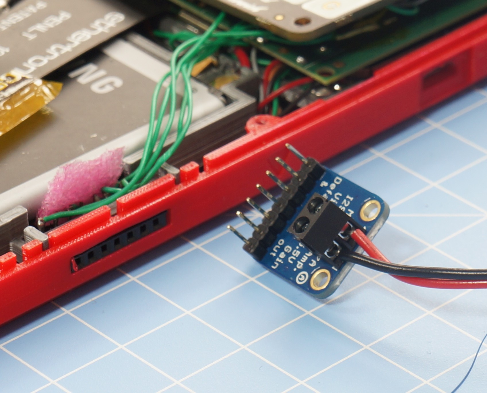
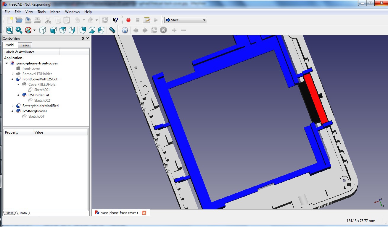
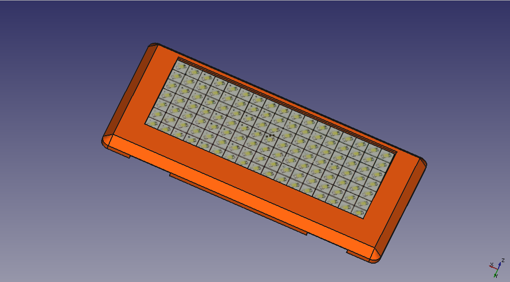
I ended up cutting a slot in the front case, designed to hold a 7 pin 0.1” female header for the I2S amp.
The 3W Adafruit Class D Amplifier plugs into the female header. The front cover modifications are best shown in the below picture:
I cut the battery holder a bit to ensure that the header can easily be inserted into place. The red piece is a small U shaped part that I ended up gluing to the header for positioning it tight.
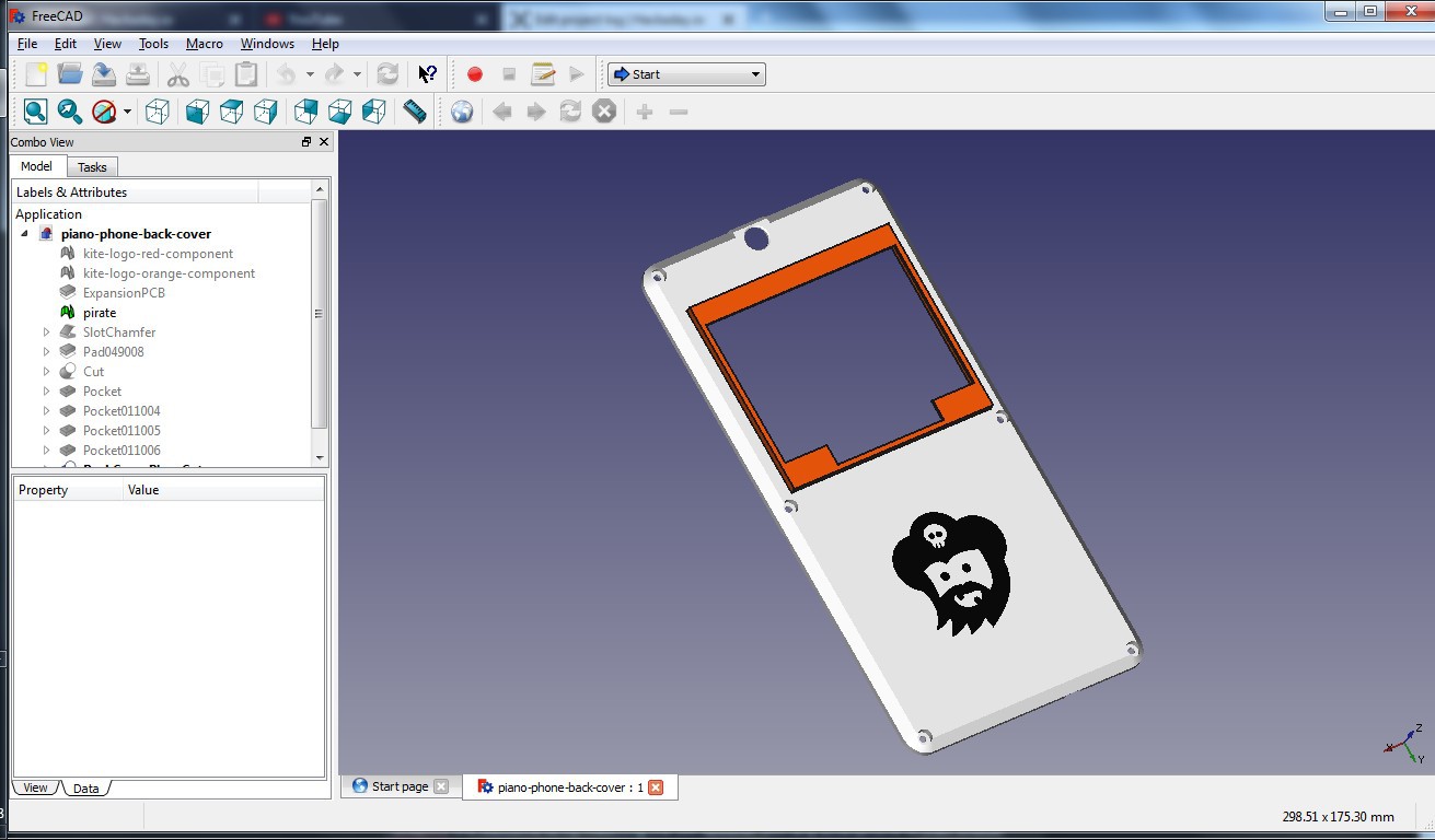
The Piano HAT needs a holder to seat it. The back case needs modifications too.
Note that the Piano HAT is modelled upside down - not a problem due to the rectangular geometry of the HAT.
Everything looks really neat at this stage. The case is a joy to use. Two more pictures, ere we end. Side view to show how less the Piano HAT jets out:
And one with the I2S amplifier plugged in:
The music pumped out by that speakers is quite LOUD too. Sceptics are welcome to try matching the 3W speaker with any smartphone of their choice. The audio folks would appreciate the I2S output coming right at them on the 0.1" header.
All done? Almost. One last bit remains - starting the piano server at boot. The piano server runs in the chroot environment. We need to start it on boot. For that, Kite has a hook – a script /system/bin/hwsetup.sh is run with root permissions on boot. That’s a great place to start the piano server. We do that by making a change in hwsetup.sh:
# Start Linux chroot environment
start chroot
sleep3 # Wait for the servertostart
# Start the piano serveron boot
env PATH=/bin:/usr/bin /system/xbin/chroot /data/local/linux /bin/bash /home/kite/piano/server.sh
After changing the script, we need a reboot. And then we are ready. To rock & roll.
First came the desktop. Then came the laptop. And the netbook. And the smartphone. There was talk of “convergence”. That somehow didn’t go well as planned.
With KiteBoard, we did plan for convergence. To that end, we kept the display connector reasonably generic – generic enough so that we could support a variety of actual displays by creating a new “display interface board”. The following possibilities can be supported with an appropriate interface board:
a standard display + capacitive touch module (these are used in common smartphones)
HDMI with audio output
LVDS displays, with or without a touch panel
RGB displays, with or without a touch panel
DisplayPort
VGA!?
That should pretty much cover all display technologies that one would want to reasonably use with Kite.
Kite’s display connector includes a bunch of MIPI DSI signals (4 data+1 clock– all of them differential pairs), PWM, I2C, I2S, a few GPIOs, and power. All these make it possible to connect KiteBoard to any display. Up until now, we have only shown the 5” phone display connected to the phone… with an intermediate display board. That worked well till now.
When I call Kite a “smartphone” kit, people start thinking in a restrictive manner. Fair enough – given the state of today’s smartphones. However, Kite is more like a “swiss army knife” of mobile computing. To demonstrate that, in this post, I show how you can connect the KitePhone to a HDMI display.
To make that happen, we have created a compact HDMI board, pictured below.
The display flex (that we used with the display board) is used to connect this to the KiteBoard. The below animation shows how this works.
The HDMI board converts the MIPI signals to HDMI using a “bridge” chip – ADV7535. This bridge chip takes audio input over the I2S lines, and renders the audio output over HDMI. The bridge chip is configured and controlled using I2C – through a kernel driver. Those interested in the hardware details of the HDMI board are requested to refer to the schematic.
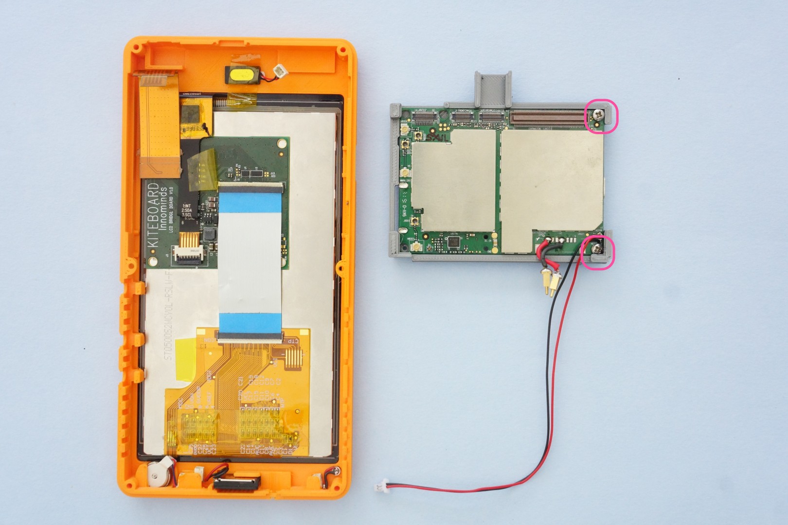
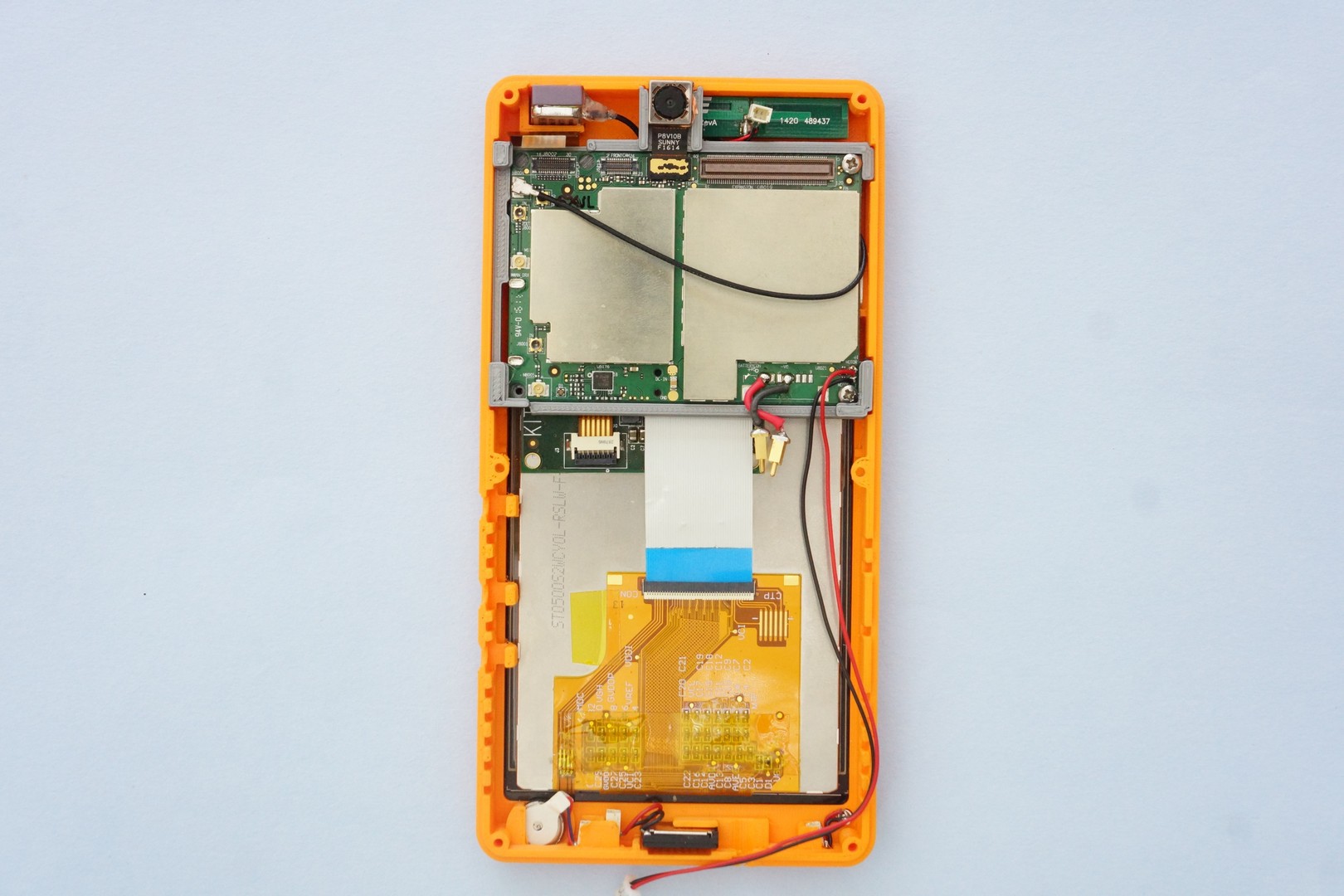
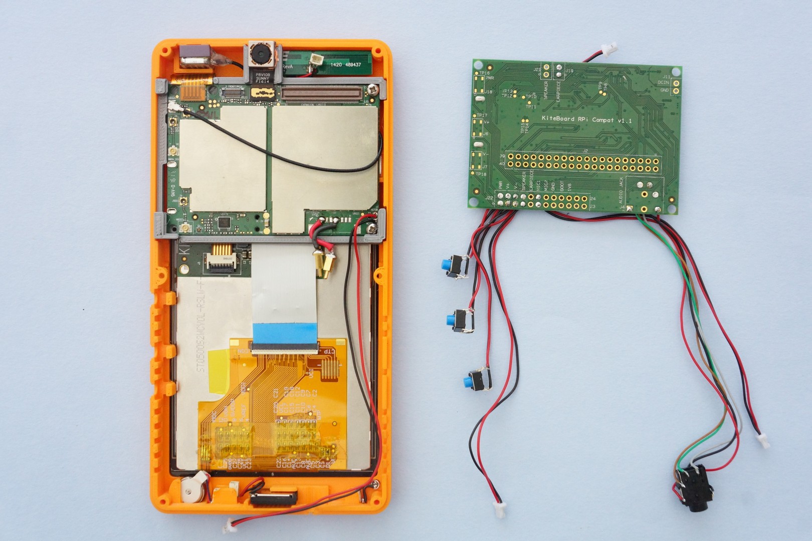
How do we make this work with the phone, though? The casing does not have any provision for HDMI, so we will have to open the phone. Using the screwdriver, we open the back cover of the phone. Then, gently disconnect the earpiece connector. Unplug the expansion board. The display connector is now accessible. Disconnect the display panel. Connect the HDMI board in place of the display panel. Connect the HDMI board to a HDMI monitor. Ensure that the monitor is powered on. Next, connect the expansion board back in its position. Turn ON the device by pressing the power button. Keep the Volume Up button pressed.
The vibration motor will announce that the device powered on, but you won’t see anything on the display. and you will now be in the bootloader mode. After a few seconds, you will see images on the HDMI screen – the familiar “android” boot animation.
How did this work? If you are familiar with Android, you know that pressing the volume UP key while turning on the phone takes you to Android “recovery”. The “recovery” mode generally invokes a kernel & a set of userspace utilities which handle the recovery aspect.
In my case, I replaced the recovery with a copy of my kernel boot image, with one difference: the recovery image is configured to use HDMI in place of the default 5” display panel. Due to this implementation, you do not not see the splash screen (the bootloader is responsible for the splash screen –it did not change – the HDMI monitor complains at this point about bad timing). As soon as the kernel boots and Android is up, you start seeing images on the HDMI monitor.
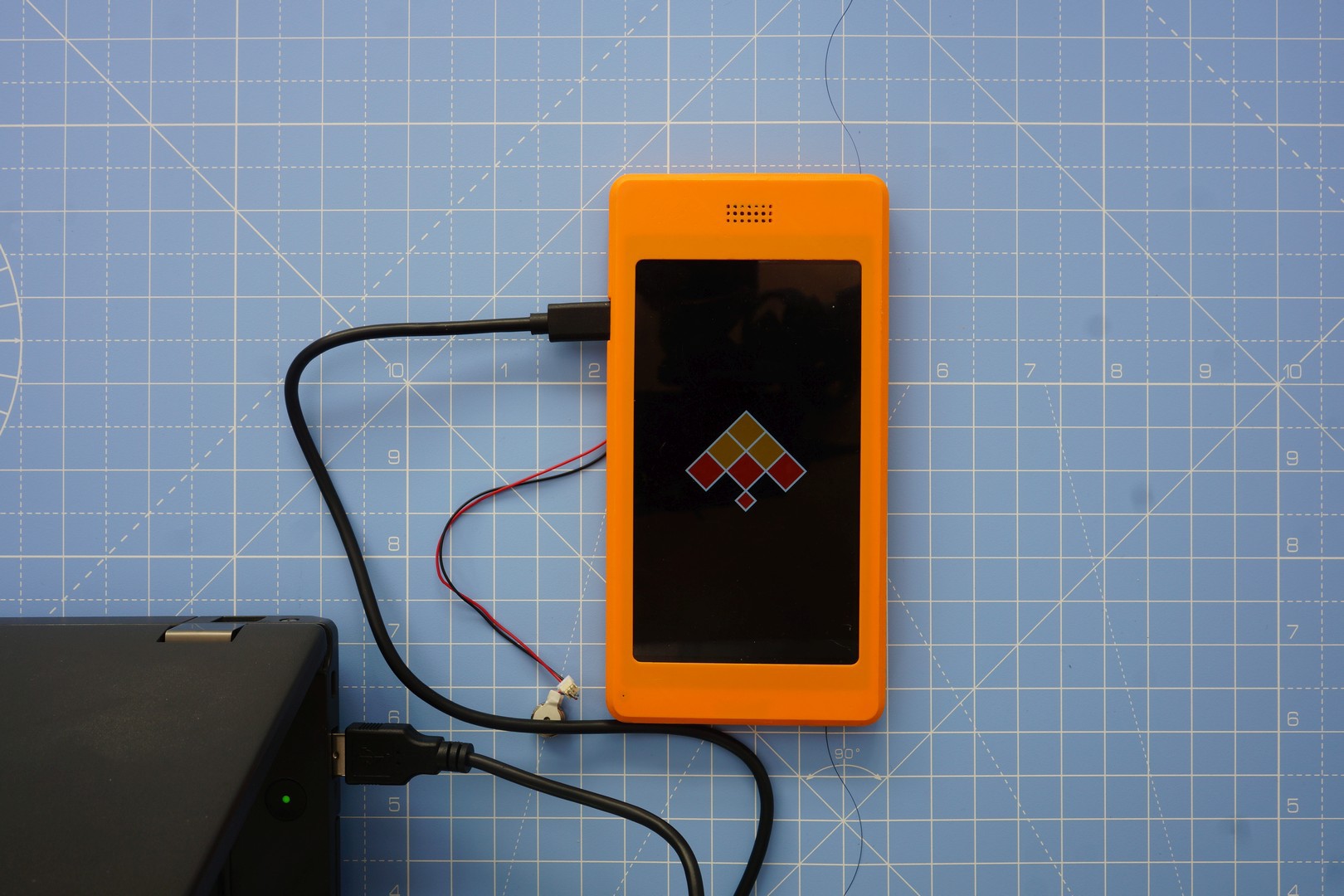
It's a simple three step process to configure recovery in this way. Use a USB cable to connect Kite to your laptop, and then punching some commands in that shell:
The last command boots the device to recovery – i.e. with HDMI enabled, in this case.
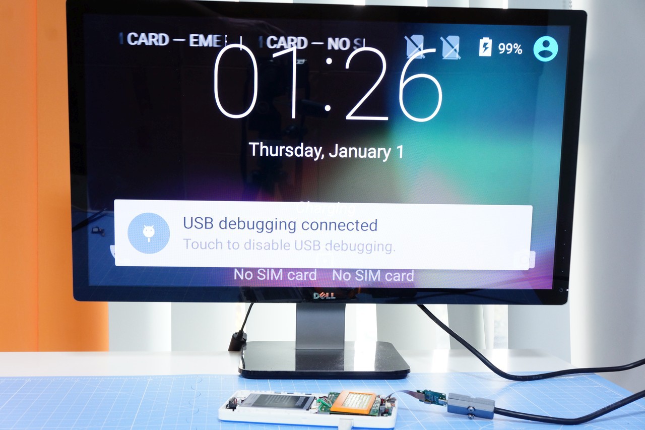
After the android boot animation, in a few seconds, we see the lock screen. Nice! But wait it’s all jumbled up?
Android still thinks that it's a phone screen. Not to worry - that's easy to fix using adb
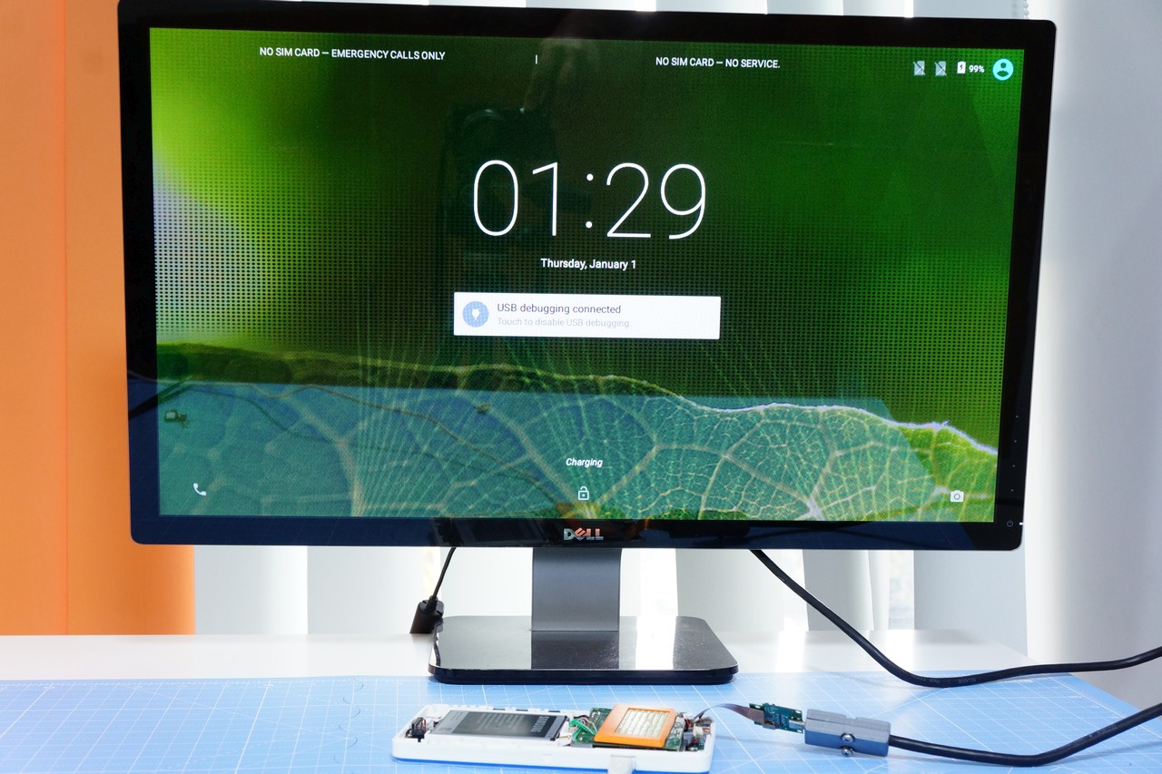
$ adb shell wm density 160$ adb reboot
After the device reboots, the desktop will now seem natural.
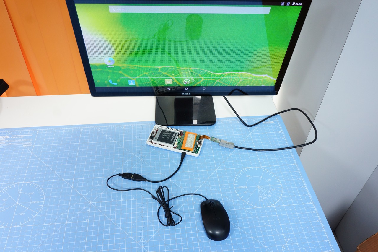
So, what do we do now? In a short while, the screen will turn off & go to sleep. If you press the power button, it will come back. There is no touch screen, so we need a mouse to interact with the screen.
KiteBoard has a single OTG port. You may connect the USB mouse to the OTG port & get started. Unlock the screen & move around in Android. The navigation bar is still on-screen, so you can use the “back” button from there. The camera works too. And the other things as well.
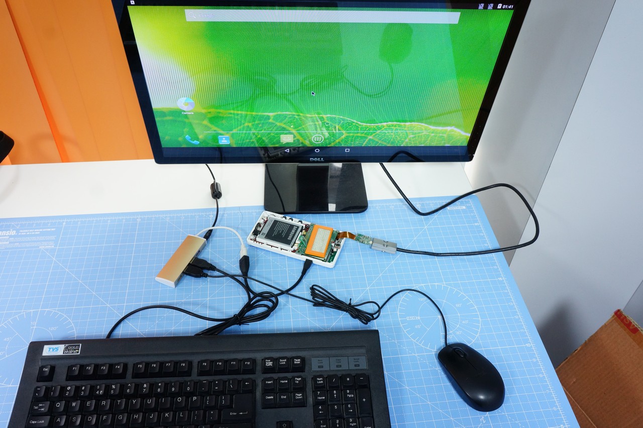
HDMI is all about productivity. That possibly means a keyboard too, right? Put that powered USB hub to good use. Use a keyboard & a mouse. You can now do some email in comfort, and maybe spreadsheets… Having a keyboard simplified a lot of things. You'll also find that the ESC button is equivalent to the BACK button in Android!
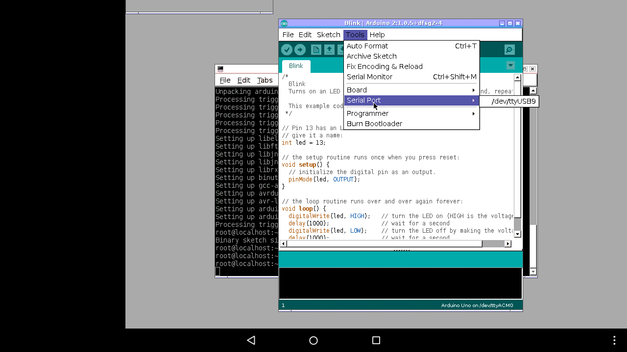
How about something more interesting? Like, say, programming that Arduino sitting on your desk? Yes, there are “apps” to do that. However, wouldn’t it be nice if would could just use the standard Arduino IDE on the device. KiteBoard can run a Debian chroot environment when needed, with SSH enabled. In the chroot environment, we could run an X server. The Arduino IDE can then be run inside that environment.
To start the chroot environment, you could do:
$adb root
$ adb shell start chroot
That will do this once - but won't work across reboots. So, you could edit /system/bin/hwsetup.sh. This is the hardware setup script that the KiteBoard runs at boot.
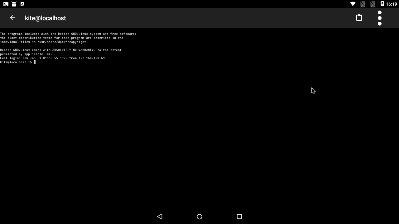
Let’s SSH into the chroot environment. The ConnectBot app is your friend. Host localhost, username kite, and password 123 will get you in. (Yeah, security risk, I know.)
Now, you can install the AndroidVNC client (It’s ancient, but it works) using FDroid. The server is localhost:5901, that’s all you need to know. After the VNC client connects, you may use the X desktop. The X environment can is functional, but can take a bit of getting used to. In any case, you can double click on the desktop & start a terminal.
Inside the terminal, install the Arduino IDE.
$ sudo apt-get install Arduino$ arduino
Connect the Arduino to the USB hub. The Arduino shows up as /dev/ttyACM0 .Load the sketch, like you always do...
And blink that LED !
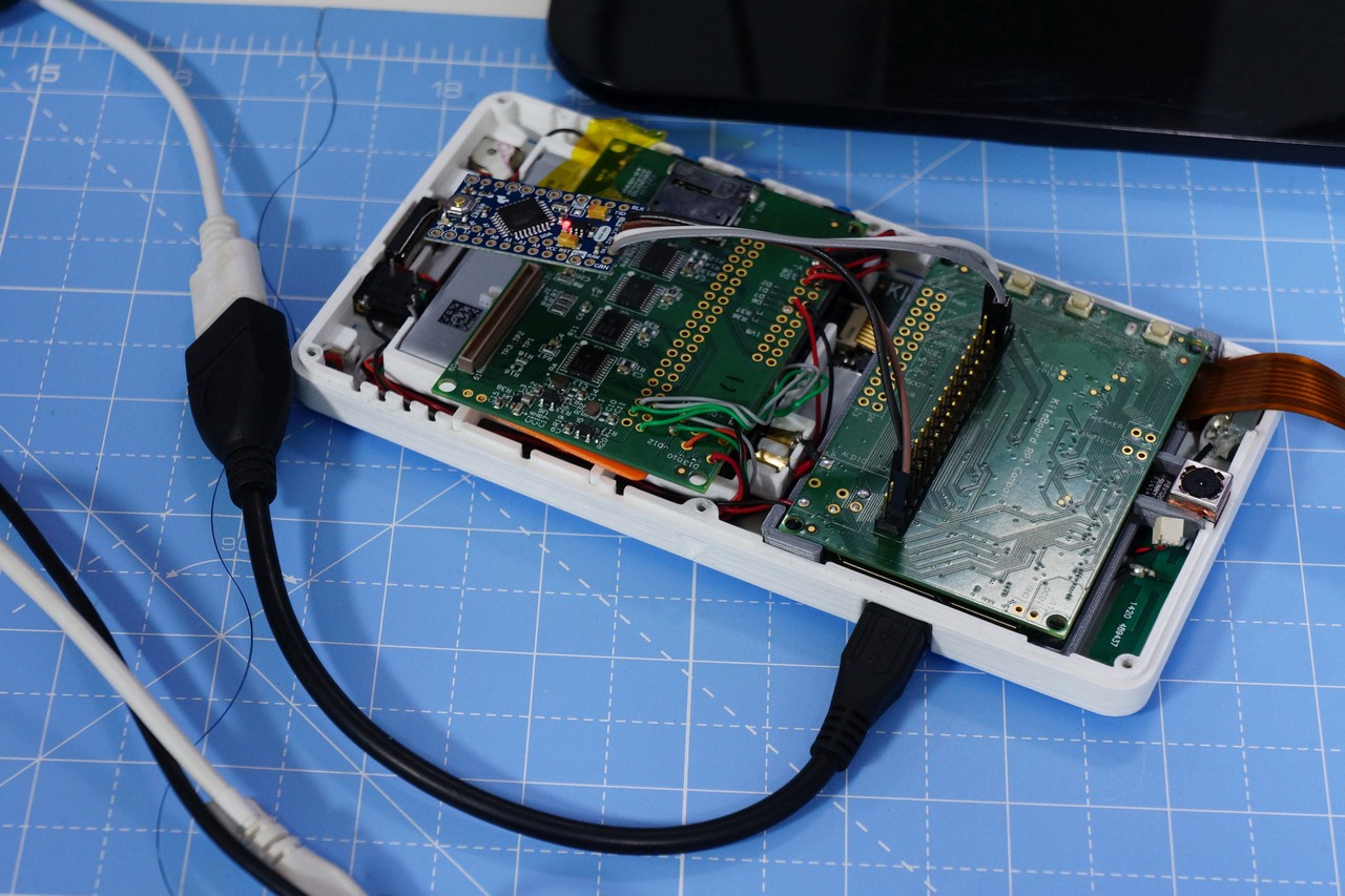
Excited already? But wait, we can make life a little more interesting. Wouldn’t it be cooler if you could just use an Arduino Pro Mini instead of that large Arduino? That would make good use of the Raspberry Pi compatibility on the expansion board.
The expansion board has the 40 pin HAT compatible footprint. We could connect an Adafruit Arduino Pro Mini (3.3V version) to that connector, and power it with the 3.3V output. To make my life easier, I took an extra expansion board & soldered a 40 pin header on it. The expansion board has a provision for SMD standard buttons – which I have populated on this expansion board. At this point, I thought that I was ready to use the Arduino IDE to blink that LED on the 3.3V Arduino Pro Mini.
Not so fast. Turned out that Arduino just wouldn’t detect the serial port… There are two serial ports on KiteBoard – the system debug port (this can be disabled when required - /dev/ttyHSL0), and a second serial port /dev/ttyHS0. Both of them aren’t recognized/detected by the Arduino IDE. As always, google and stack exchange had the required workarounds.
I ended up adding the following line to hwsetup.sh to create workaround this problem – basically symlink /dev/ttyUSB9 to /dev/ttyHS0:
ln -s /dev/ttyHS0 /dev/ttyUSB9
Now, Arduino knows ttyUSB9 !
After this change, I am able to program the Arduino Pro Mini from Arduino, running inside the chroot environment, accessible via VNC inside the Android desktop. And I amin controlwith my keyboard & mouse.
At this point, my phone is effectively my lab-in-the-pocket… Close to convergence ? What do you think ?
After you are done with HDMI -- how do you get back to using the phone screen ? Well - disconnect the HDMI, connect back the phone screen, close the cover & boot the phone as usual ! Oh yeah, the UI will appear a bit jumbled; that can be fixed by changing the screen density to 320:
$ adb shell wm density 320
As you might guess, there are "apps" to do this last step as well !
Before I end, let me say that the software isn’t in a “plug & play” state right now. In our current implementation, we have a functional HDMI display output that looks works like a “display panel”. In technical terms, the resolution is hard-coded in the kernel. In a complete HDMI implementation, the actual connected display must be queried, and EDID data must be used to setup the resolution. Apart from that, everything works...
The current KiteBoard has a single display connector - that results in a bit of ugliness. With KiteBoard v2, we will have two display connectors. Potentially, we could have both the HDMI and the "phone" screen active at the same time... or two HDMI displays powered by a single Kite v2. I am eagerly awaiting that day...
The best way to learn, apparently, is by teaching. In my case, the best way to understand what I am doing has been by explaining it to others. For, that requires me to structure things such that they are easy to understand. The best explanations are the ones that need no jargon.
Ever since I made the intro video of Kite, I have had the desire to take a short intro session for students. I was sharing the video with everyone. One of my friends, Channa Bankapur, watched the video. He's a brilliant chap (an ex-googler, in case you want a quick intro). He asked me if I would be interested in involving students. It took us quite some time to arrange a session. Channa teaches at PES University, a top-tier engineering college in Bangalore. Big thanks to him for making this happen!
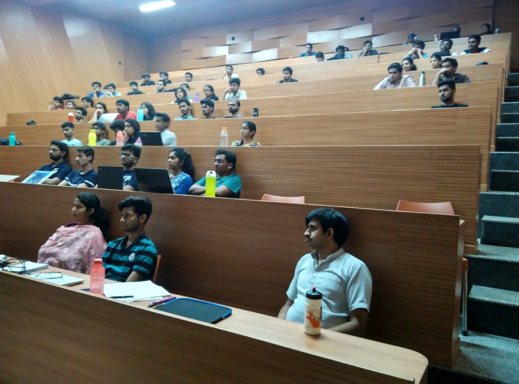
Given the multi-disciplinary nature of Kite, I had asked him to invite students from at-least a few departments - Computer Science, Electronics and Mechanical. 300 students said they'd come. 70 actually showed up. Due to another technical fest that happened to run at the same time, there was a bit of a last minute change of plans. My session got moved from morning to afternoon. That possibly caused a bit of a dip in the turn-out.
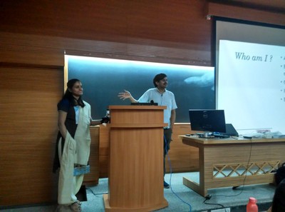
The 70 students were almost split 60:40 between computer science, and electronics students. I had prepared a reasonable presentation deck. Along with me, from my team, I took Shalini & Saravana to help with the presentation.
Interestingly, I found that most students own phones in the price range 10k-20k INR. Only 2 among them had actually used a 3D printer. A lot of them had used Arduino & the Pi. As expected, most of them use a smartphone as a consumer device. It's powerful enough for programming, they get that - but the display is too small to do anything serious.
I had a good time explaining the motivation behind making the Kite kit. To spice things up, I had requested that a student make a presentation about "here's how smartphones work". Priya Nayak from PESU made the presentation - to my surprise she had dug up one of my favourite quotes by Alan Kay.
People who are really serious about software should make their own hardware
It also kind of proved my point - that Android is a black-box even to students who are into technical education. In any case, I was happy to continue my preset story line.
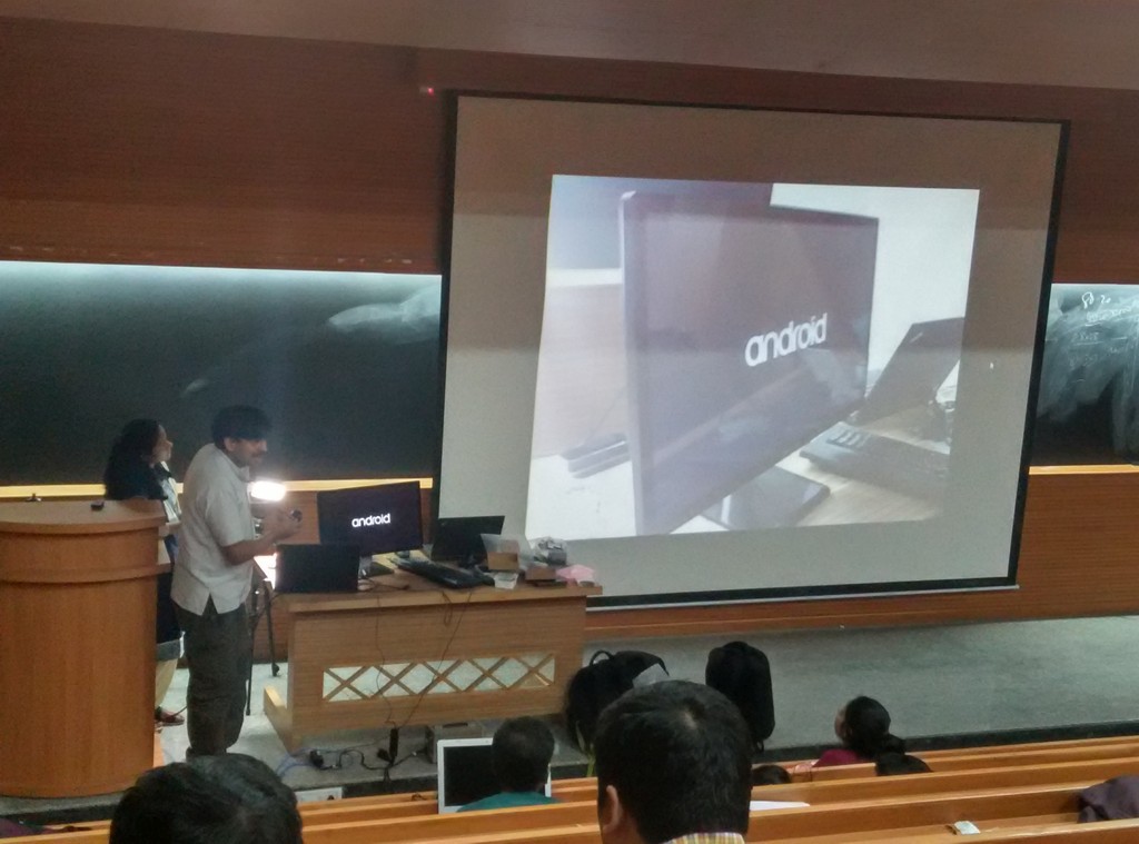
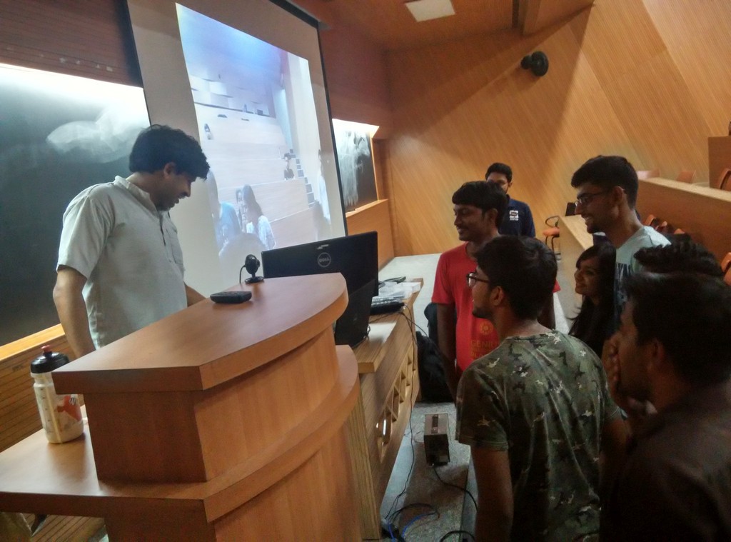
I showed many prototypes - including my new Piano Phone. For the first time, I also showed off the HDMI capability of Kite. Both of these blew away the students, I thought. I also did obligatory screwdriver tear-downs of Kite. There was a hearty applause at the end of the presentation, and many questions from the students. One question about a Satellite phone popped up, and I was happy to show some work-in-progress too. Post presentation, I had a detailed discussion with a couple of students. They seemed interested to do some VR - and I pointed out the upcoming two display support in KiteBoard v2. I also explained the community angle in Kite, and the open interfaces(e.g. display). All in all, that went better than I expected...
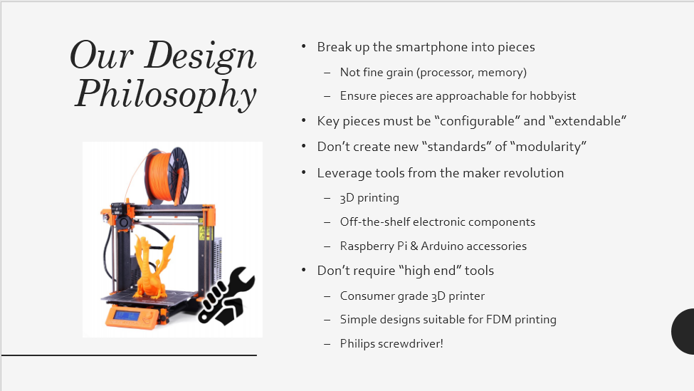
I have uploaded the slides for the session to SlideShare . I expect to refine my presentation next time... teaching truly is the best way to learn & understand.
Here are my favourite three slides from the presentation. Smartphone vs PC:
"who is impacted":
and the "design philosophy" behind Kite:
A few pictures from Channa's shaky camera... Introducing the speakers...
The HDMI moment - at the end of the demo. That was worth all the wait... at the end of the phones.
That looks less than 70 .. ? Students having a closer look at the protos + Q&A:
I have plans of starting a Kickstarter campaign for this kit - real soon. We have plans to upgrade KiteBoard to v2.0 - a supercharged upgrade, if I may say so. The new board will have powerful specs like a Octa-core 2GHz processor, 2GB RAM, 16 GB of storage, powerful GPU, WiFI a/c, two displays (both MIPI @1080p), 2 cameras, 4K video encode/decode, WiFi ac, USB 3.0, fast battery charging, plus a modem of course...
These are fairly top high end specs, but then we are thinking: let's take this to the next level. I am seriously considering to make the next version an Open Hardware design. If you look at all the files I have released till now, you find find files for side boards and flex cables. The main board, however, is not open at this time. This is set to change.
This could have some rather far reaching impact for various category of folks. I am not aware of any compact board that is so powerful, integrates a modem, is feature rich & allows the design of a compact, battery operated device. I am guessing that this will be heaven for students, startups, research folks, entrepreneurs, ... in short, anyone whose idea needs a mobile platform for their idea.
So -- hackaday, I ask you : how would you like the idea of an Open Hardware Android Phone ? ("mobile platform" would be more accurate, rather than "phone", really, if you see our design... )
Also, do weigh in on what you believe would be expectations from such a design - hopefully your dreams & maybe even rants.
After we built Poorna, our base model, we had a bit of a problem. We had engineered a lot of flexibility into our design. Folks asked us, “what can you do with this?”. My typical response, invariably, would be “a lot – anything, in fact”. It took me a while to figure out that this was not working…. “anything” is “nothing” unless shown to be “something”. After that realization, I set about building some demos.
Explaining a new idea (and certainly something with wide possibilities like Kite) to folks is a lot of work. In today’s world, getting attention & creating a first impression is very important. After racking my brains for a while, I hit upon the idea of adding a name badge to my phone. This is the same model that’s shown in my pocket in our intro video:
We call this model “Minchu”, meaning “Lightning” in the Kannada language (spoken in Karnataka state in India; Bengaluru/Bangalore is the capital city, and also our base). The idea behind this name will be explained towards the end of this post.
I have visited Shenzhen, in China, a couple of times. Each time, I have come back impressed with the bewildering variety of stuff sold at Huaqiangbei, all at shocking prices of course. My favorite trinkets, purchased there four years ago, were a few scrolling LED badges. Back then, I had not seen these online, but now Aliexpress seems to have a lot of choices. These badges feature bright LEDs of a single color – red (cheapest), green, blue and white(30% more expensive than red). They pack a lot of SMD LEDs, worked off a battery, the whole thing was programmable with a USB cable, and included a rechargeable battery plus a magnetic clip at the back. In any case, I was hooked - I must have purchased 10 pieces, at-least, at bargain prices! They were a big hit in my office as well. I sold a few (at cost) to a few lucky colleagues. Walking around, with one pinned to my shirt pocket, was a surefire way of grabbing attention at conferences. A great conversation starter!
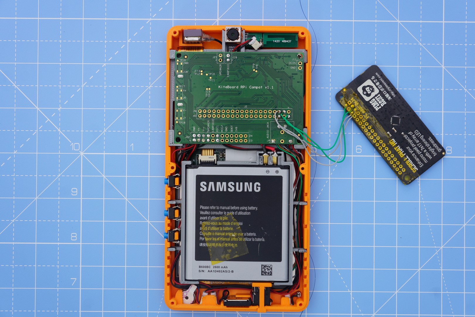
These commercial name badge is programmed via a USB cable. The badge uses a PL2303 serial to USB converter. I could have used the same name badge itself, with a bit of reverse engineering. However, I was more interested in showing off the Raspberry Pi compatibility that we had built. So, I chose to add the Pimoroni Scroll pHAT HD to Poorna.
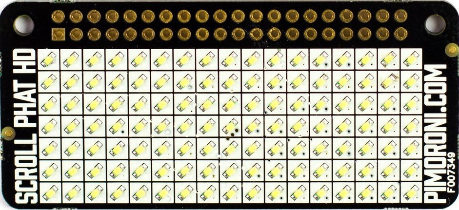
The Pimoroni Scroll pHAT HD features 17x7 LEDs. It is based on the IS31FL3731 LED matrix driver chip. Prior to ordering, I had a look at the datasheet of the IS31FL3731. A couple of features grabbed my attention:
Picture mode and animation mode
8 frames memory for animations
Would it be possible to use these features to animate my name on the pHAT while my phone is in sleep? Kite is a phone platform. It features very low power consumption (<5mA) even when connected to the cellular network. If I could configure the pHAT in “animation mode” & then send the phone to sleep, then the animation would be visible when the phone is in sleep, without any additional CPU usage.
Being the lazy types, I searched online to see if folks were using the animation feature. Nothing relevant turned up. That kind of made sense. Most folks use a Scroll pHAT HD with a Raspberry Pi, on Linux. Animation is typically implemented by repeated draw calls, followed by calls to update(). Generally, folks don’t put the Raspberry Pi to sleep while expecting it to do something useful….
To accommodate the Scroll pHAT HD inside Poorna, we need to modify the back cover. But before we do that, let’s get the electronics to work, shall we? My last update covered Kite, and mechanical assembly of Poorna. However, I didn't say anything about software and interfacing electronics. Most of this post will cover those aspects. All the files referenced in this post are available in minchu-v01.zip.
Information required to interface the Scroll pHAT HD is available at pinout.xyz. Basically, the pHAT is powered by 5V. I2C (two wires – SDA, SCL) is used for communication with the IS31FL3731 chip. The Scroll pHAT HD is generally used on a Raspberry Pi with the headers soldered. To make a compact case, these need to be removed.
With the back cover removed, Kite’s expansion board is visible. We use 4 wires to connect 5V, GND, SDA and SCL signals from the Raspberry pi compatibility connector on the expansion board to the Scroll pHAT HD. What could be simpler? (Note the 4 wires in the picture below)
We need to next verify that KiteBoard can “talk” to the Scroll pHAT HD, as well as implement the required software to get the whole thing to work. Pimoroni maintains a Python module for the Scroll pHAT HD – this works on the Raspberry Pi, running Linux. KiteBoard runs Android; Linux software won’t work directly in our environment. What are our options?
I could, of course port the python library to Android first. To start with, that’s way too much work. Also, after porting, if the thing doesn’t work – do I blame my port, or the hardware?
Fortunately, we have engineered an easy way out: we have a chroot environment, running right inside Android. The chroot environment has Debian Jessie, which can run Python – and so the pHAT examples, unmodified. Inside this chroot environment, you can now test the pHAT almost like you normally would… Could life be simpler? Here are the exact commands:
$ adb root # need root to start chroot environment
$ adb shell start chroot # this sets up somestuff, including SSH too, but we don’t use it below
$ adb shell # commands after this run on the device
# unset LD_PRELOAD
# chroot /data/local/linux /bin/bash
# export PATH=/bin:/usr/bin
# cd /opt/scroll-phat-hd/examples
# ./hello-world.py
Scroll pHAT HD: Hello World
Scrolls “Hello World” across the screen
In a 5x7 pixel large font.
Press Ctrl+C to exit!
Here's the output (Note the USB cable - that's exactly how you'd use adb on your Android phone): At this point, we have checked the hardware. It is fun to run the other examples too. I like swirl.py – it transports me to a magical time in my childhood – where we would eagerly wait for the TV programmes to begin; the TV would spring to life with Doordarshan’s Signature Tune.
Python is a fantastic, easy to use programming environment. The Pimoroni library does most of the work required for the pHAT. If we can figure out the appropriate register configuration for “animation mode”, then we can easily implement it in python. Page 9 of the datasheet has an overview of the relevant registers:
The Configuration Register, and Auto Play Configuration registers are described in detail in page 12. Basically, the chip can work in one of three modes:
Picture mode – default, used by most projects
Auto Frame Play mode – which is what we are trying to use
Audio Frame Play mode – apparently a mode where the LEDs are modulated by audio. This gives me some interesting project ideas... For now though, I will stick with our current quest – getting the auto frame play mode to work.
At this point, I should note that Scroll pHAT HD has relatively few LEDs (never mind the “HD” included in the name). 17x7 is not a lot of pixels to show any name completely. Even with a tiny font, like 3x5, the display can only show about 4 characters at a time. Scrolling will be required. The pHAT has 8 frames, so I can scroll one letter at a time. This way, I can show my full name, “Shree Kumar” in 8 frames. We can keep scrolling the name endlessly, with a bit of a delay between the frames.
The chip allows a configurable delay, in steps of 11 ms, with a maximum delay of 64*11=704 ms. The chip supports 8 frames – one of which can be displayed at a time. It also supports configurable start & end frames. For my name, we’ll have to use all frames.
The Scroll pHAT HD python library works in the following way:
Programs draw a complete frame, and then show() it.
Two frames (frame 0 and 1) are used, as a double buffering scheme. Frame 1 is drawn to, when frame 0 is visible on the pHAT, and vice-versa. The show() function manages this scheme.
I added a "specific_buffer" parameter to the show() function. specific_buffer can be used to , optionally draw the image to any frame (0 to 7), without showing it on the screen:
defshow(self, specific_buffer=None):"""Show the buffer contents on the display.
The buffer is copied, then scrolling, rotation and flip y/x
transforms applied before taking a 17x7 slice and displaying.
specific_buffer is a frame number from 0 to 7. If this value
is specified, then the image is drawn on the frame, without
changing the state of the display.
"""if specific_buffer:
next_frame = specific_buffer
else:
next_frame = 0if self._current_frame == 1else0
display_shape = self.get_shape()
display_buffer = self._grow_buffer(self.buf, display_shape)
for axis in [0,1]:
ifnot self._scroll[axis] == 0:
display_buffer = numpy.roll(display_buffer, -self._scroll[axis], axis=axis)
# Chop a width * height window out of the display buffer
display_buffer = display_buffer[:display_shape[0], :display_shape[1]]
if self._flipx:
display_buffer = numpy.flipud(display_buffer)
if self._flipy:
display_buffer = nuMpy.fliplr(display_buffer)
if self._rotate:
display_buffer = numpy.rot90(display_buffer, self._rotate)
output = [0for x in range(144)]
for x in range(self._width):
for y in range(self._height):
idx = self._pixel_addr(x, self._height-(y+1))
try:
output[idx] = self._gamma_table[int(display_buffer[x][y] * self._brightness)]
except IndexError:
output[idx] = 0
self._bank(next_frame)
offset = 0for chunk in self._chunk(output, 32):
#print(chunk)
self.i2c.write_i2c_block_data(self.address, _COLOR_OFFSET + offset, chunk)
offset += 32# Display the buffer only if a specific buffer wasn't specified.ifnot specific_buffer:
self._frame(next_frame)
del display_buffer
Plus, I implemented a play_animation() function (in is31fl3731.py), with a configurable delay.
defplay_animation(self, delay_steps=0):# enable all LEDs in all the banksfor i in range(8):
self._bank(i)
self.i2c.write_i2c_block_data(self.address, 0, [255]*17)
# Configure animation mode, with desired speed
self._register(_CONFIG_BANK, _AUTOPLAY1_REGISTER, 0)
self._register(_CONFIG_BANK, _AUTOPLAY2_REGISTER, delay_steps)
self._register(_CONFIG_BANK, _MODE_REGISTER, _AUTOPLAY_MODE)
After play_animation() finishes, the 8 frames are automatically rendered by the IS31FL3731 chip (and hence, by the pHAT), with the configured delay.
Here’s the script that actually does the top level work, name-badge.py:
#!/usr/bin/env pythonimport scrollphathd
from scrollphathd.fonts import font3x5
print("""
Scroll pHAT HD: Name Badge
""")
#Rotate text into orientation
scrollphathd.rotate(180)
#Set a more eye-friendly default brightness
scrollphathd.set_brightness(0.5)
name = 'Shree Kumar -'
scrollphathd.write_string(name, x=0, y=1, font=font3x5, brightness=0.5)
# Draw the animation frames
for i in range(8):
scrollphathd.show(i)
scrollphathd.scroll(4)
# Start the animation - and ensure it stays even after we exit!
scrollphathd.play_animation(50)
scrollphathd.set_clear_on_exit(False)
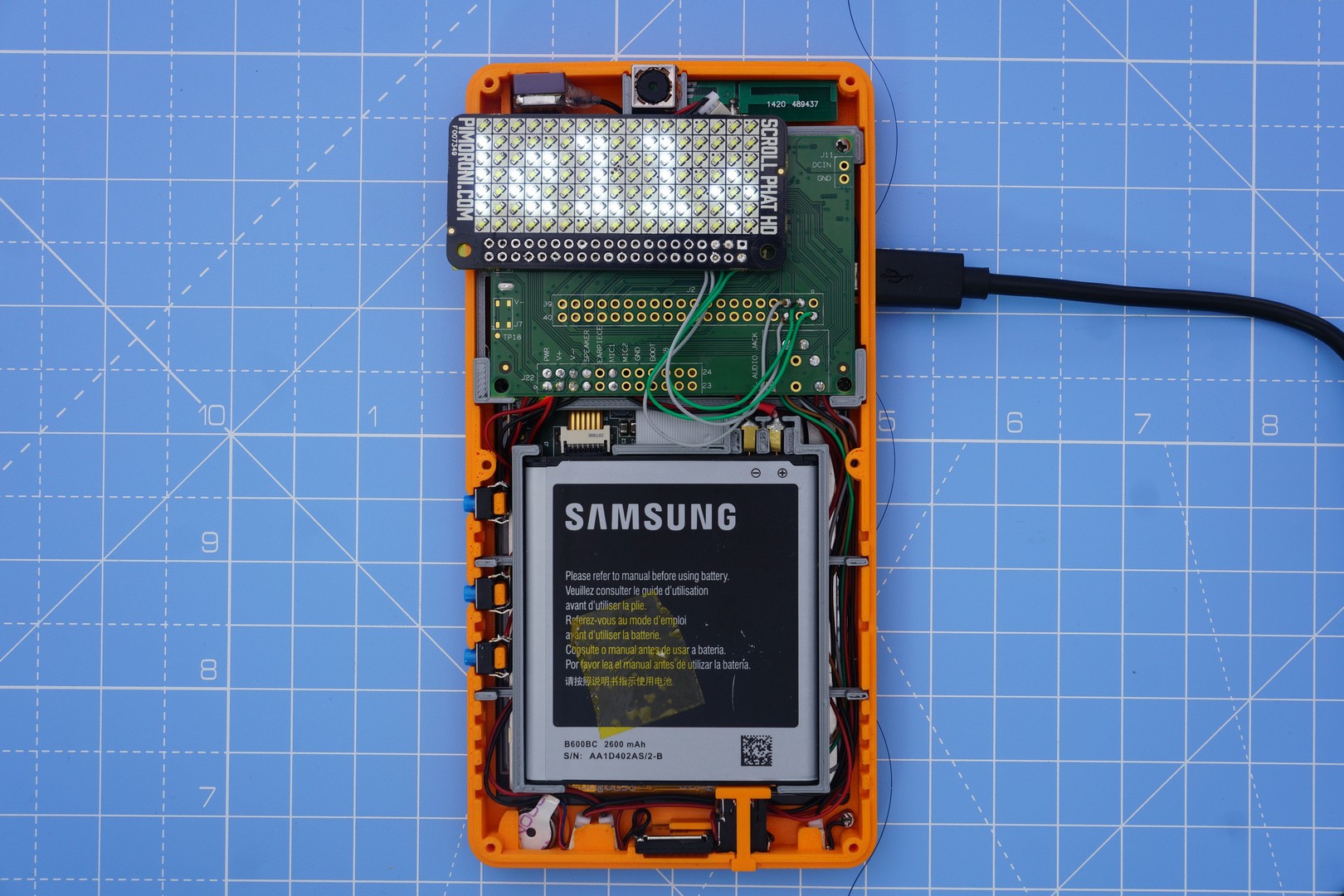
name-badge.py draws 8 frames of the name animation. With each step, the name is scrolled one letter to the left. Animation mode is activated next, with a delay of 50*11 = 550 ms (I like this speed). The script exits immediately after setting up animation mode. Normally, the library cleans up on exit – but in this case, we want the animation to keep running. The last line of code ensures the library does not clean up. When the script exits, we will see that animation keeps on running.
The expansion board (to which the pHAT is connected) supplies power to the pHAT, even when the phone is in sleep mode. I can send the device to sleep by disconnecting the USB cable, and pressing the power button (just like any Android device). The end result - the name animation keeps playing, even when the phone goes to sleep (note the screen is off). Mission accomplished?
Not quite. We need to get this scheme to work in Android, natively. We wouldn’t want to run a whole lot of other things (Linux userspace libraries, python,…) just to show a name on a badge – would we?
Android includes a large amount of software running over the Linux kernel. Android has an interesting security model that makes it close to impossible to access platform hardware directly. This makes sense – consumer hardware rarely has any pins available for usage. Typically, hardware access in Android happens through well-defined APIs. Most folks don’t add new hardware to Android – this generally requires the hardware to have some sort of mass market appeal/use case. That won’t work for us.
To make it easier for “hacks” like ours (and explaining stuff easily), we have disabled SELinux on our Android build. If we didn’t do that, we’d have to write at-least an additional layer of software to manage access to hardware.
An Android-ish solution would generally configure the badge from an application written in Java (using the Android APIs). There is no API to access I2C, so we’ll have to use C/C++ code to do that – and call that code using JNI. All hardware access in Android apps works more or less this way – but generally through an intermediary service (e.g. Camera). We follow the KISS principle, and because this badge is not for the world to use, we can directly communicate with the I2C device.
The I2C interface on KiteBoard is available as /dev/i2c-1, same as Raspberry Pi – to ensure that various pieces of software can run without modification. Luckily, the Linux kernel provides a userspace API - so we don't need to write messy kernel drivers for simple tasks. Using the userspace API, we can talk to the pHAT & get everything to work. It is time now to port the Pimoroni library (with our changes) to C/C++. I wrote a small C++ wrapper to make a decent library, plus a test program to check the display. (These files are in minchu-v01.zip - see directory android-source/kite/pimoroni-scroll-phat-hd after extracting the zip.)
I can build the code inside the device’s Android source tree; it could also be built with the NDK. The build inside the Android source tree requires a few steps:
$ cd <ANDROID_SOURCE_ROOT>
$ source build/envsetup.sh
$ lunch kite-userdebug
$ cd kite/pimoroni-scroll-phat-hd
$ mm
The “mm” command builds the targets inside the current directory. The executable binary is generated in $ANDROID_SOURCE_ROOT/out/target/product/kite/system/bin/test_test_lcd_gfx.
All the Android userspace resides in the “system” partition. This is the “ROM” – mostly mounted as read-only in consumer phones. To run our code, it is easiest to push the executable there. We need to mount the system partition in read-write mode & copy the file to the partition. Let's do that with adb:
On Android, /system/bin is part of PATH – so the executable can be used from the command line without explicitly mentioning it's path. The port is good - so I can now see my name on the badge. The name keeps animating even after the program exits. So far, so good.
Now that the underlying functionality has been implemented, we need to make this accessible from Android – Java code. To call the native code from Java, we need to implement a JNI (Java Native Interface) wrapper – a shared library that will be loaded & invoked by the Java code. Here is ScrollPHATHD.java - a class with all native methods. The class loads libphatgfx.so - which contains the implementation of all the functions... oops "methods" I should say.
package com.isquare.kite.exthw;
publicclassScrollPHATHD{
static {
System.loadLibrary("phatgfx");
}
publicstaticnativebooleaninit();
publicstaticnativevoiddeinit();
publicstaticvoidflip(){show(-1);}
publicstaticnativevoidshow(int page);
publicstaticnativevoidanimate(int delaySteps);
publicstaticnativevoidpicture_mode();
publicstaticnativevoidset_fb_size(int w, int h);
publicstaticnativeintget_fb_width();
publicstaticnativeintget_fb_height();
publicstaticnativevoidscroll(int x, int y);
publicstaticnativevoidscroll_to(int x, int y);
publicstaticnativevoidwrap(boolean x_wrap, boolean y_wrap);
publicstaticnativevoidset_pixel(int x, int y, float brightness);
publicstaticnativevoidfill(float brightness, int x, int y, int w, int h);
publicstaticnativevoidclear();
publicstaticnativevoiddraw_char(int x, int y, char ch, float brightness, boolean reverse_video);
publicstaticnativevoiddraw_string(String msg, int x, int y, float brightness, boolean horizontal, boolean reverse_video);
};
With that done, we now need a standard Android application to program the badge… I want the phone to work in “badge” mode when it is in sleep. Android applications can get notifications of important activities – by implementing what’s known as a “BroadcastReceiver”. Android has “Intent”s for various events – including ACTION_SCREEN_OFF, which you probably guessed is fired just before the screen goes off. We hook on to this screen off event, and configure the Scroll pHAT HD in animation mode. After we finish, the device goes to sleep – with the animation running. Sweet!
However, the story isn’t complete yet. We are violating a fundamental law of nature here… everything that turns ON must turn OFF, eventually – else the battery will drain! We can fix that by stopping the animation when the screen turns ON. Like the screen off, Android defines a screen on event as well, ACTION_SCREEN_ON. When we receive this, we turn off the screen. Done. Here’s the code:
You’ll need to compile & run the "phat" application (inside minchu-v01.zip, see android-app/phathd) to see it working. Use Android studio for the same. Next, let’s modify the case & include the pHAT inside it.
The pHAT is connected to the expansion board with four wires. The PCB and the components are about 4 mm thick. The completed case can’t add much thickness, if we want to take it around. in our pockets We can achieve minimum thickness, if the pHAT sits right above the expansion board.
To modify the rear cover, we will use FreeCAD, version 0.16. This open source application makes it possible to do the design in an easy-to-use user interface. FreeCAD is parametric - meaning we can measure the physical dimensions of the pHAT and fit it in. The parametric nature allows easy changes - simplifying trial & error. Something too tight? Just change the dimensions a bit by tweaking a number – no need to redo the entire design.
This post is too small to give a tutorial on FreeCAD; I will cover the important steps. The model created below is available in minchu-v01.zip, as "freecad/minchu.FCStd". This freecad model file includes measured dimensions in a spreadsheet - these dimensions are referenced to create the actual shapes.
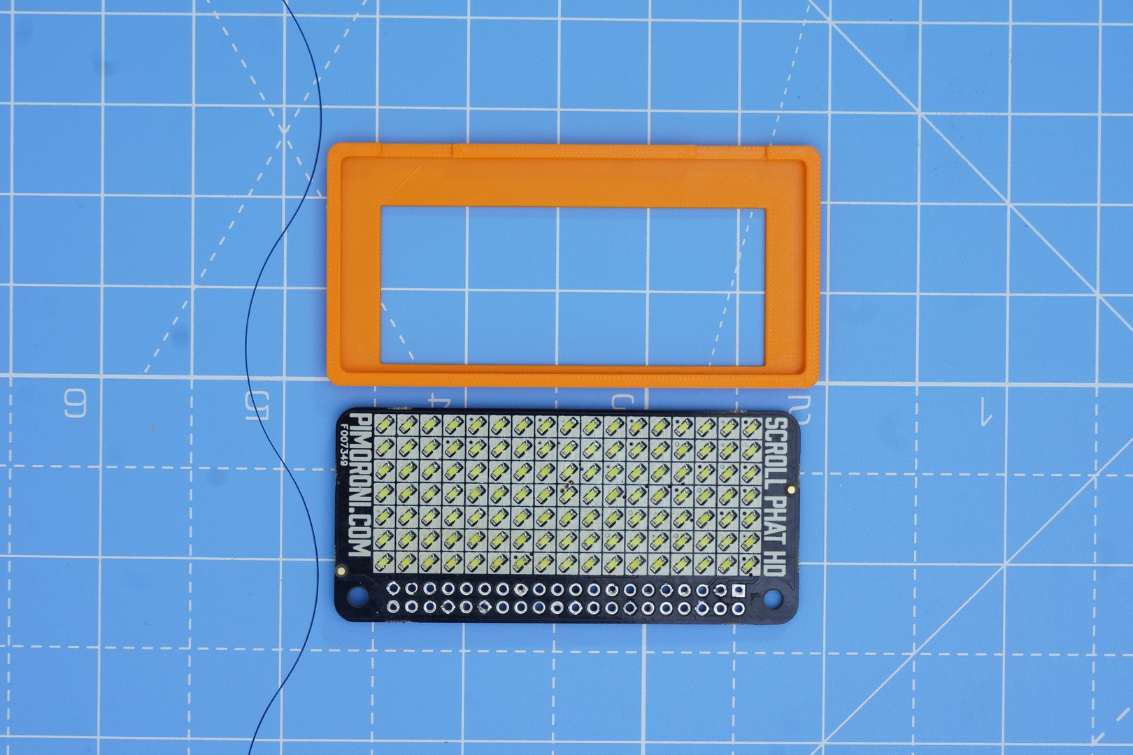
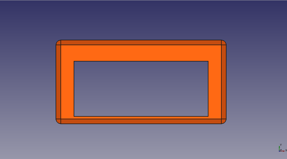
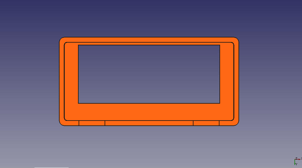
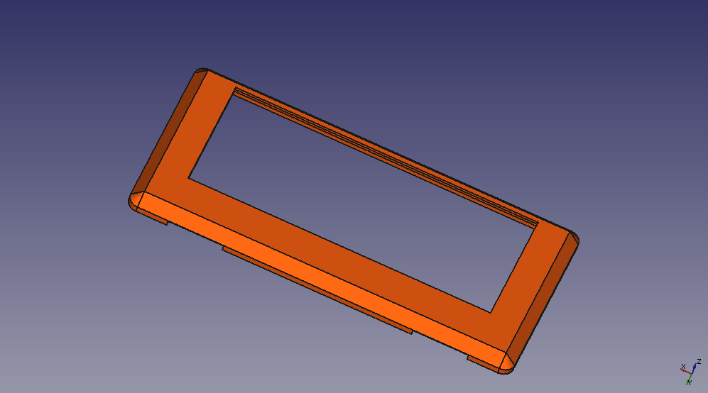
Let’s begin by designing a simple “holder” that fits the Scroll pHAT HD. The Scroll pHAT HD can be inserted inside this holder, with the LEDs visible. Let’s bevel the sides of the holder.
On the bottom side of the holder, there is a small cut in the plastic to help route the wires.
The complete part looks like this:
To get some idea of how things might turn out, we'll use an image of the top side of the Scroll pHAT HD:
Keeping that image in the same space as our design gives us:
This last exercise gave me a lot of confidence - if the cut matches the picture, then the print must come right... After half an hour of printing, I get the part:
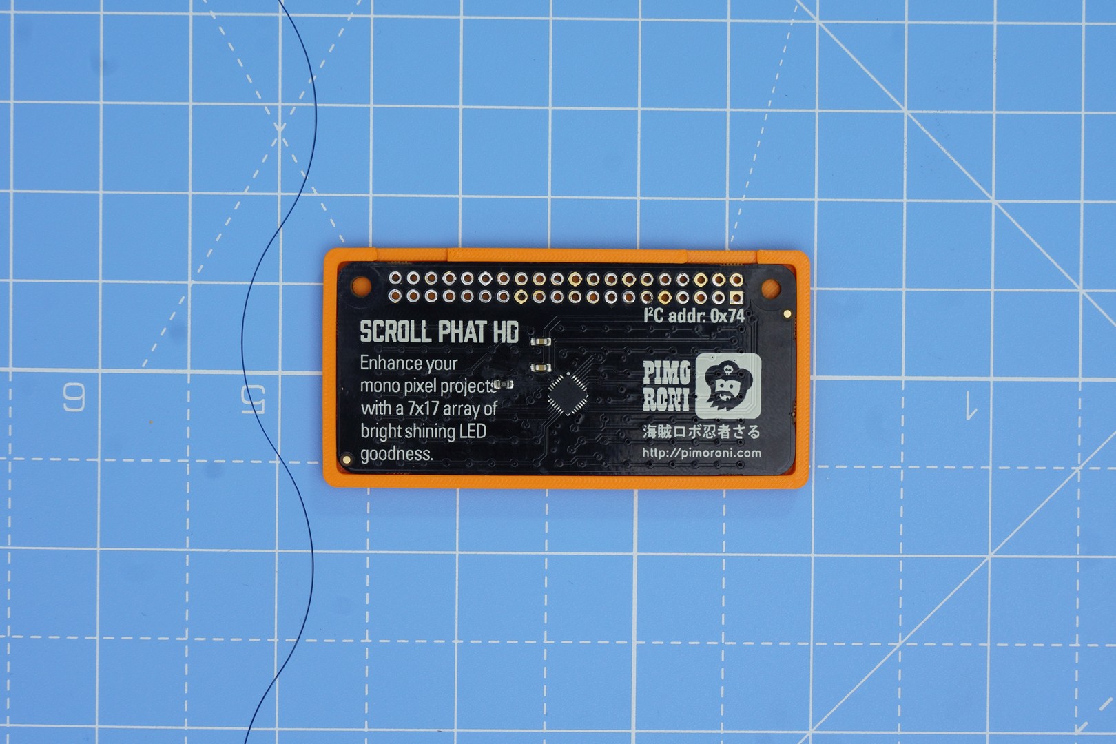
Lets put the pHAT in the cover – fits nicely! I used a tolerance of 0.1mm – which seems to give me a satisfying fit.
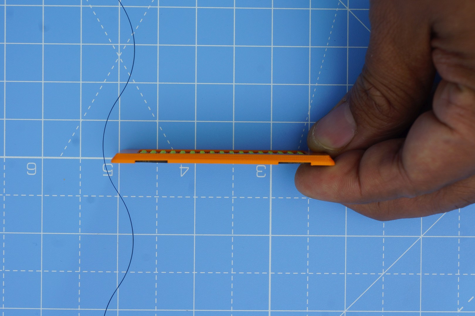
Let’s take a side view
Let’s place this over our open phone to see how best we can put everything together.
I figured this will work best. With the phone in my shirt pocket, if I want my name to be visible, then I want to have the pHAT as close to the rear camera as possible.
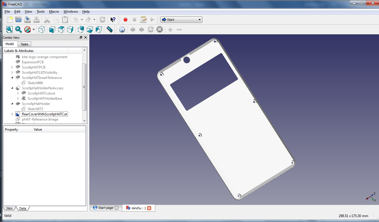
To accommodate this holder, I need to cut a negative of this into the holder. That’s a simple Boolean operation on two solids in FreeCAD. Picture below shows the modified rear cover, after the Boolean operation:
When the holder sits in the slot, the pHAT PCB will touch the expansion board, more or less. This can make a reasonable assembly. (with the phat cover visible)
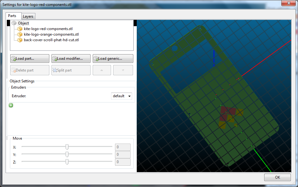
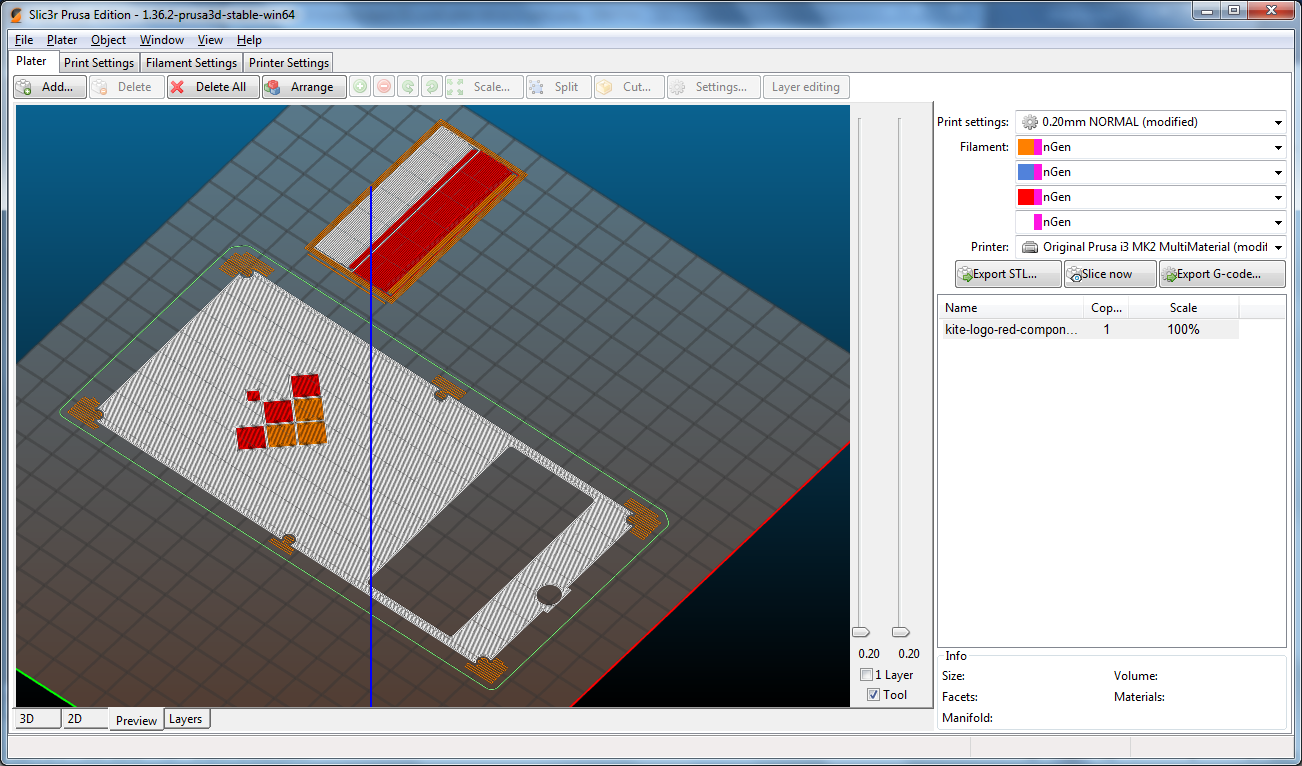
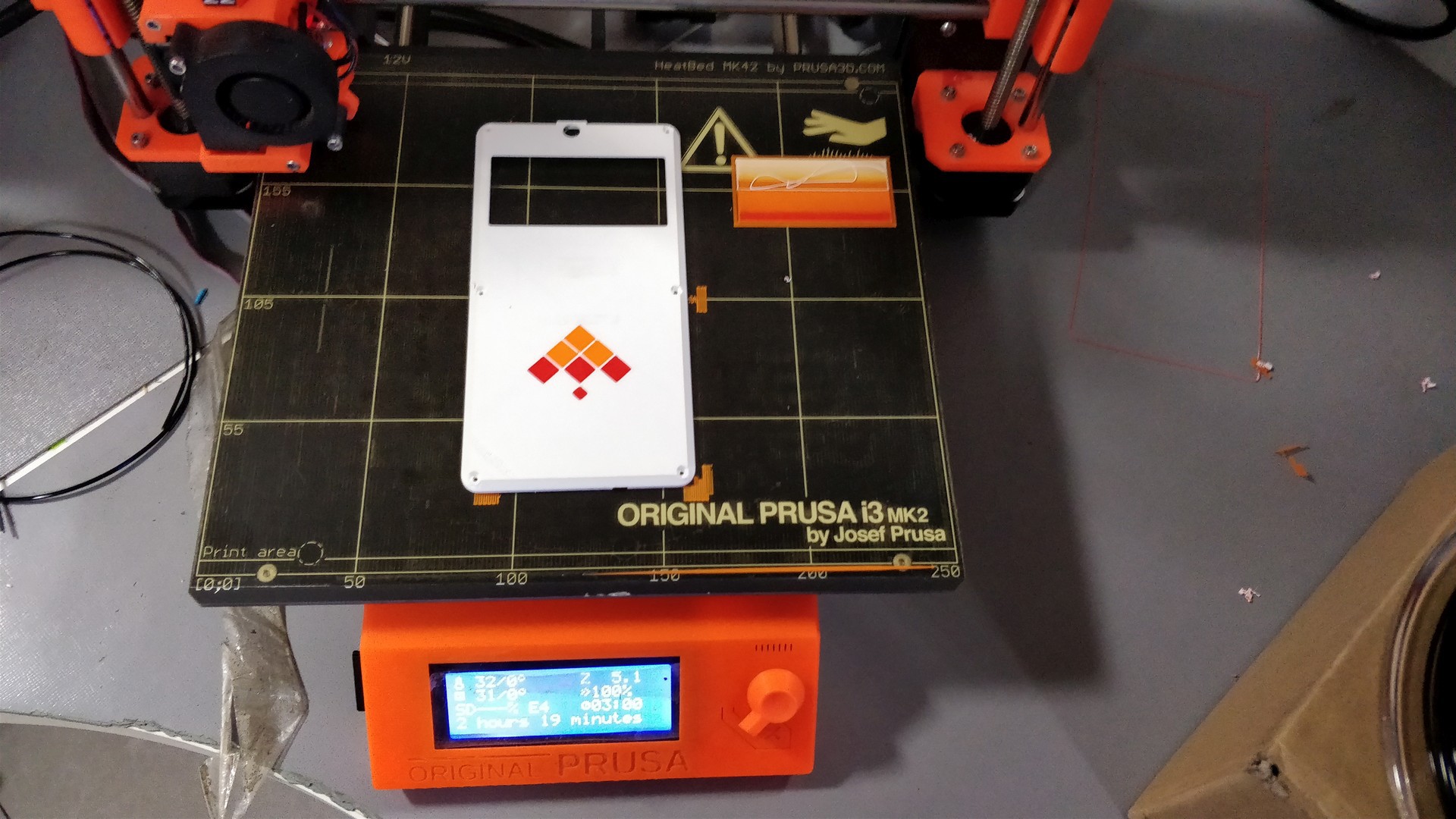
We can now print the rear cover. I have a Prusa i3 MK2 printer, with the Multimaterial printing capability – with the ability to print up-to 4 colors. To spice things up, I have included the Kite logo (orange & red parts) – hope you noticed it in the last picture. I use Slic3r for slicing the model. Each part is assigned a different extruder – 1 for orange logo piece, 3 for red logo piece, and 4 for back cover (white).
The first layer of the sliced model, for reference:
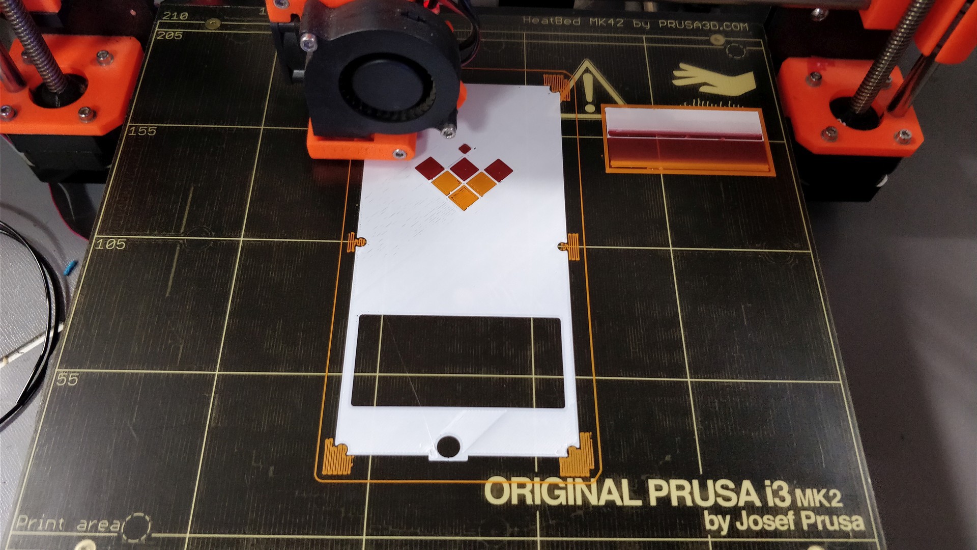
Everything looks fine, so I export the gcode to an SD card, and start the print. The first layer went reasonably well – that’s the important part with most 3D prints!
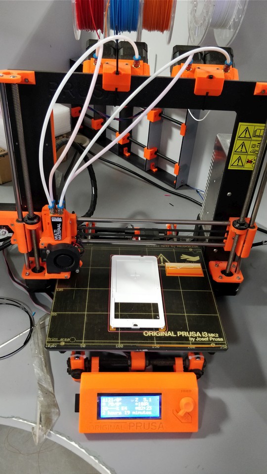
All's well that begins, and ends well. After 2 hours, 19 minutes, here's the result.
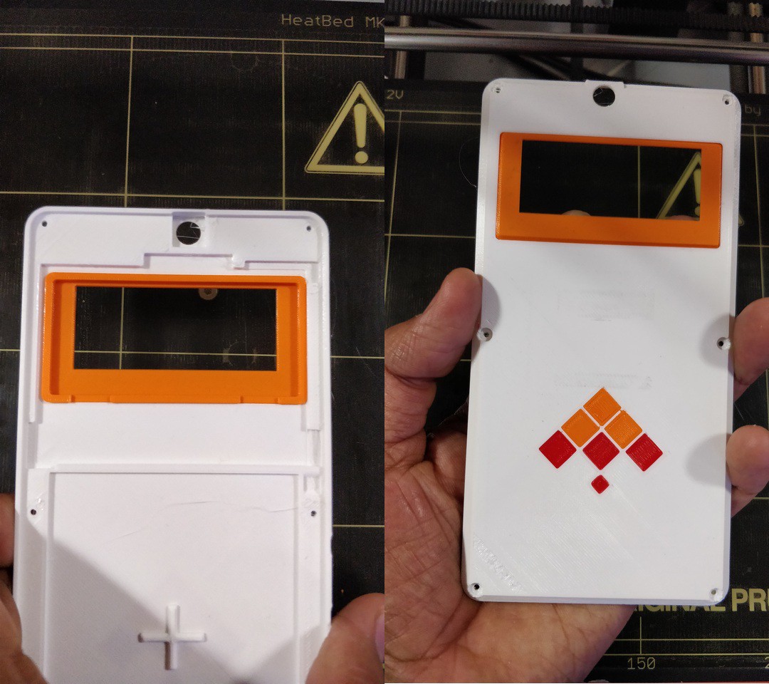
Cleaned up a bit of the support material on the screw holes. A little visual detailing can help hide all the flaws beautifully…
Time now to see if the pHAT cover will fit the modified rear cover or not. Thanks to our meticulous approach – it seems to fit well!
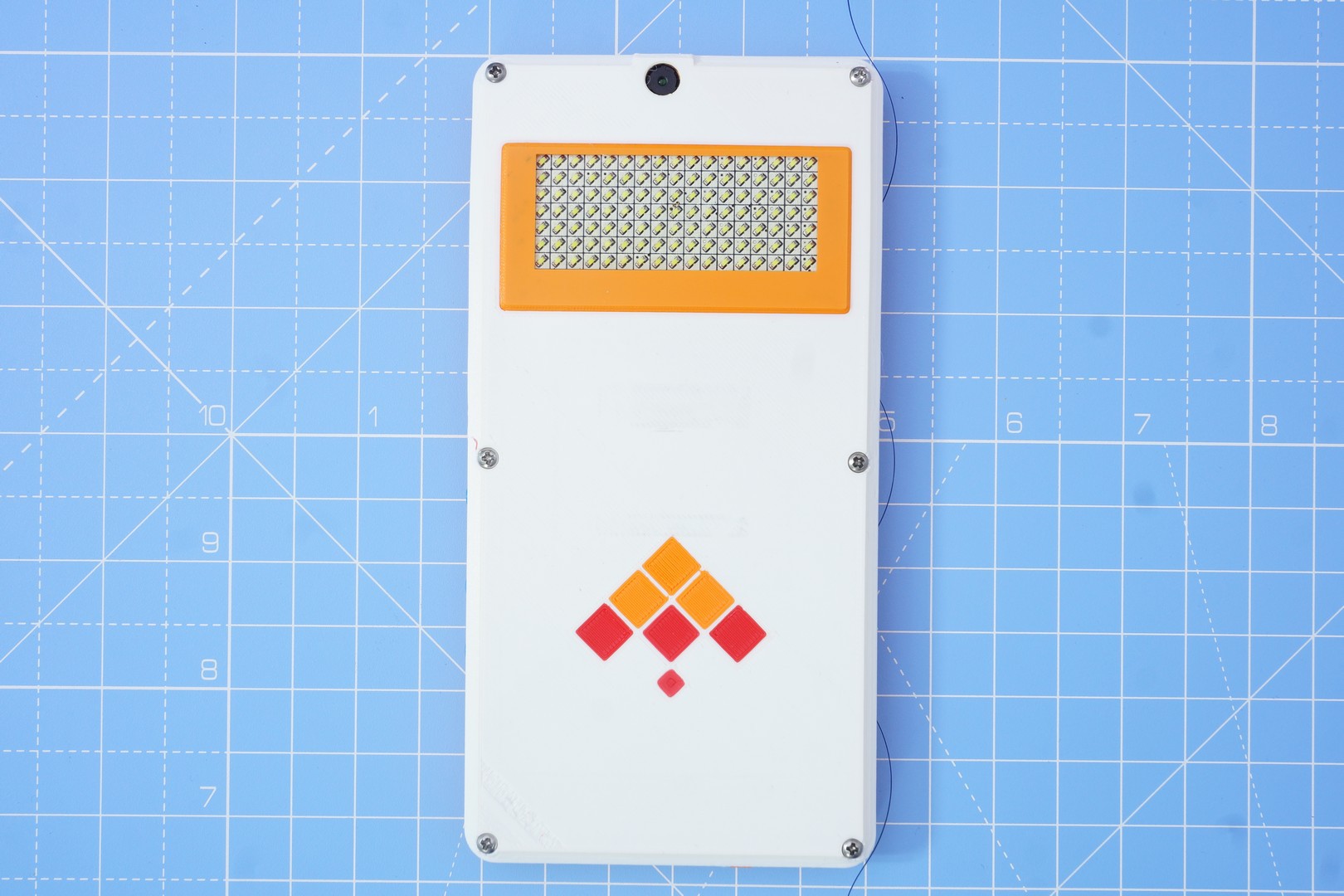
Great! Now, it is time to assemble the complete device. Reach out for the screwdriver to finish the masterpiece… I maybe going a bit over the top here, but let’s just say that I was overjoyed to see the complete thing. Look at the image below & judge for yourself!
Still here with me ? Great. It’s time now to explain what’s behind the name “Minchu”. As mentioned earlier, the word “Minchu” means “Lightning” in Kannada – my mother tongue (my actual mother tongue is a dialect of Kannada, but this level of detail should be good enough for now).
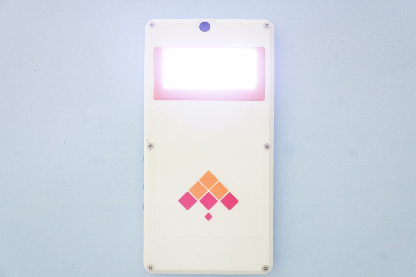
What’s lightning got to do with the name badge? The Pimoroni Scroll pHAT HD features 17x7 insanely bright LEDs; you wouldn’t want to stare at it with all LEDs running at 100% brightness. It’s about as bright a light as you can add to your phone – hence the name “Minchu”. The “dazzling” effect is best captured here… I wouldn’t stare at the light – if I were you!
Android is an open source project. Andriod ROMs have long put this to great use. Many features implemented in popular ROMs have found their way back into AOSP. Consumer phones don’t allow you to add hardware to them – so the amount of customization possible is limited. Kite gives you the awesome ability to add your own hardware –that alone opens-up opportunity for makers to solve various problems that will never be addressed by consumer phones... Let’s get back to the torch and show you how to modify Android.
We can use this LED panel as a bright torch. Android has this “Torch” widget in QuickSettings – accessible when you pull down the statusbar on the screen. Wouldn’t it be cool if we could use this to turn ON our LED panel? Of course, glad you asked.
Let’s hack into the “SystemUI” component in the Android framework. We will implement a QuickSettings “Tile” for the pHAT based torch. As a simple implementation, this “Tile” fires an “intent” when the torch state requires change (ON/OFF). In response to the intent, our Android application can turn all the LEDs ON and OFF. The source code is too long to reproduce here – please refer PHATFlashlightTile.java for details. We can then tap into the flashlight action, and use this new tile implementation (instead of the default "FlashlightTile") :
After making these changes, we need to recompile Android, and flash the "system" partition (pro devs can use some shortcuts too – but let’s keep it simple for now).
KiteBoard is Android based - you can use fastboot to flash the system partition, just like you would with your phone:
$ cd <ANDROID_SOURCE_ROOT>
$ source build/envsetup.sh
$ lunch kite-userdebug
$ make -j8 # Build
$ adb reboot bootloader
$ fastboot flash system out/target/product/kite/system.img
$ fastboot reboot
After the phone boots, run the phat demo app. Then use the flashlight icon on the main screen to see your changes in action:
That’s it – we are done for now. The flashlight example is a simple, but useful example. With our Raspberry Pi compatibility, you can easily add various commonly available sensors to the phone. Not only will you be able to monitor the environment, but you could potentially implement entirely new ways of interacting with your favorite device.
What sensors would you want to add to your phone - and how would they impact Android? Please let me know in the comments below! Thanks for reading.
A KitePhone is simply a phone built using the Kite Kit. Consumer phones go through a teardown, so that folks can understand how they are built. Kite is built for makers, so we take a "build" approach here.
In this post, I will show you how we’ve put together a minimally complete model of a phone. We call this model, “Poorna”. Poorna is a Sanskrit word, commonly meaning “complete”. It can also mean “zero”, and there are philosophical interpretations too, but then I digress. Poorna is a complete phone providing functionality like the smartphone in your pocket. No additional bells & whistles, just pure Android.
Here is a short overview video (2 minutes, 17 seconds) of how to build Poorna, starting from Kite:
Still reading, and interested to learn more? Great. The complete details are down below, in quite some detail. I need to warn you again: this post is long, and extremely detailed. It details the entire kit, some design decisions, throws some light into the mechanical design, and kit assembly. If I were you, I'd grab a cup of coffee (perhaps more), and then proceed!
---------- more ----------
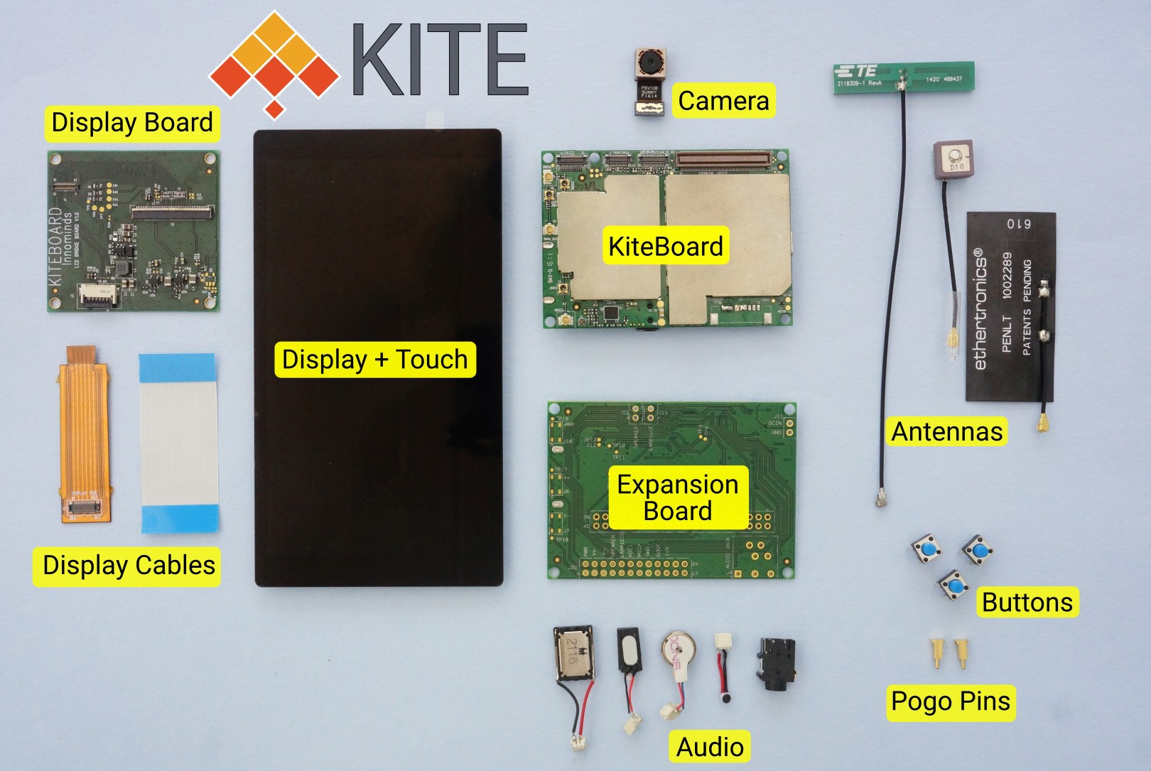
The Kit
First, let’s start with Kite, the DIY modular smartphone kit. As the video above illustrates, this kit has everything you need to build a complete phone (Minimal tools, and some soldering is required, but nothing pro level.) Let’s briefly go over the items in the kit.
The KiteBoard is the “brains” of the kit. I find it useful to think of it as the motherboard of/for a phone. KiteBoard is based on the Qualcomm MSM8916.
KiteBoard has a sub credit card form factor (70 mm x 50 mm), with a low profile – around 5.5 mm including all connectors. KiteBoard includes a modem, a quad core 64 bit 1.2 GHz ARM Cortex A53 processor (with Adreno GPU), WiFi/BT, GPS, 16 GB of onboard storage (eMMC), 1 GB of RAM, integrated 9 axis accelerometer/gyroscope/magnetometer sensor, and a LiPoly battery charger. Various connectors on KiteBoard allow you to include custom hardware features required for your project. KiteBoard’s pins work at a voltage level of 1.8V. The complete specifications of KiteBoard are here.
The expansion board converts the I/O pins of the board to 3.3V logic level, making it accessible to makers. We believe that makers must be able to use common components available to them to create devices that solve specific needs. To that end, we have provided a 40 pin Raspberry Pi compatible connector. The expansion board also makes the audio portion of the board accessible to makers. The expansion board is the same size as the KiteBoard, and stacks right on top of it.
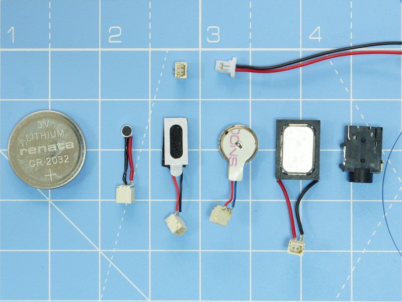
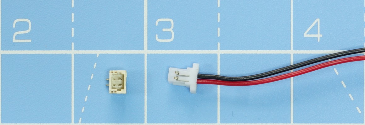
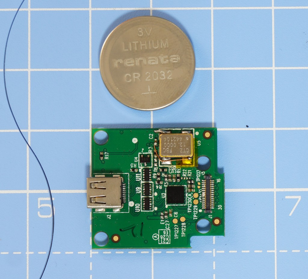
A tested speaker, microphone, earpiece, and a 3.5mm audio socket are included in the kit. We’ve carefully chosen small components here, which are still large enough to be usable. In the kit, these components are provided soldered to tiny connectors (these are 1mm pitch male shrouded headers). To get a fair idea of the size of these components, have a look at the picture below. The CR2032 battery is in the picture for a size comparison. The picture also shows 1mm pitch plug that is used to connect the audio components to the boards.
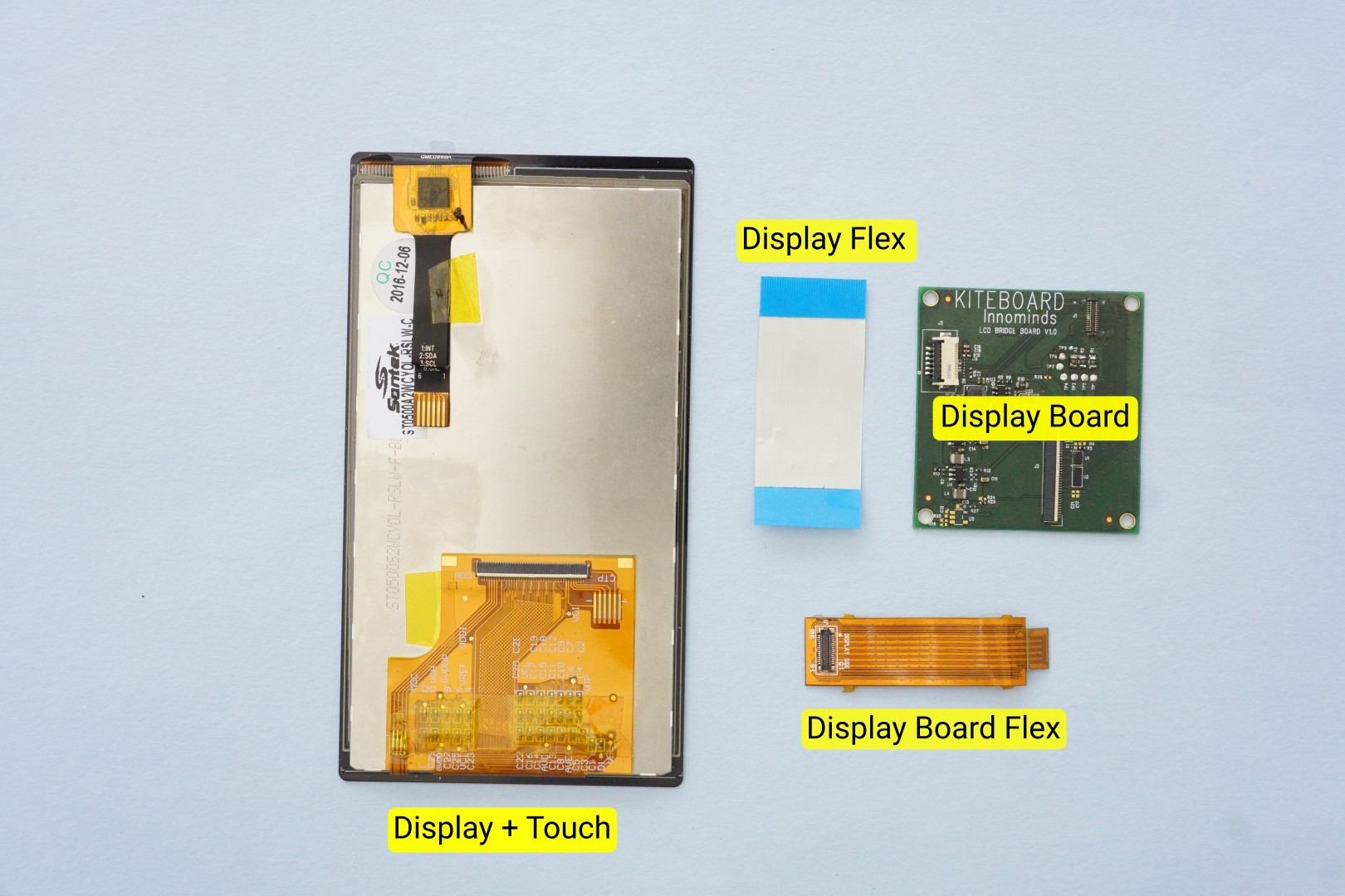
The 5 inch (diagonal) display module is one of the nicer parts of the kit, featuring 720p resolution, and an integrated 5 point capacitive touch panel. The display features excellent color reproduction. Plus, at 700 nits brightness – it’s brighter than most mid range phones that you are likely to come across... A display board and a couple of flex cables are used to the display module to KiteBoard.
The 8 MP camera module is capable of autofocus – which is crucial to its usage in a phone (or any handheld device, for that matter). We also have two flex cables in the kit that allow the camera module to be placed farther away from the board. The flex cables aren't shown in the picture, as they are not used in this build.
Kite includes separate antennas for WiFi/BT, GPS and LTE. The WiFi/BT and LTE antennas are available from DigiKey, and maybe other vendors.
To put Poorna together, the enclosure & internal board holders need to be 3D printed.
3D printing plays a major role in this project. The complete phone & everything required to hold the components in place is 3D printed. We have designed the models such that any common printer is sufficient to reproduce our results. That means minimum overhangs, 45 degree slopes and no tricky requirements for support material that is tough to cleaned up afterwards. The complete model files for Poorna have been uploaded to the site, as poorna-v01.zip .
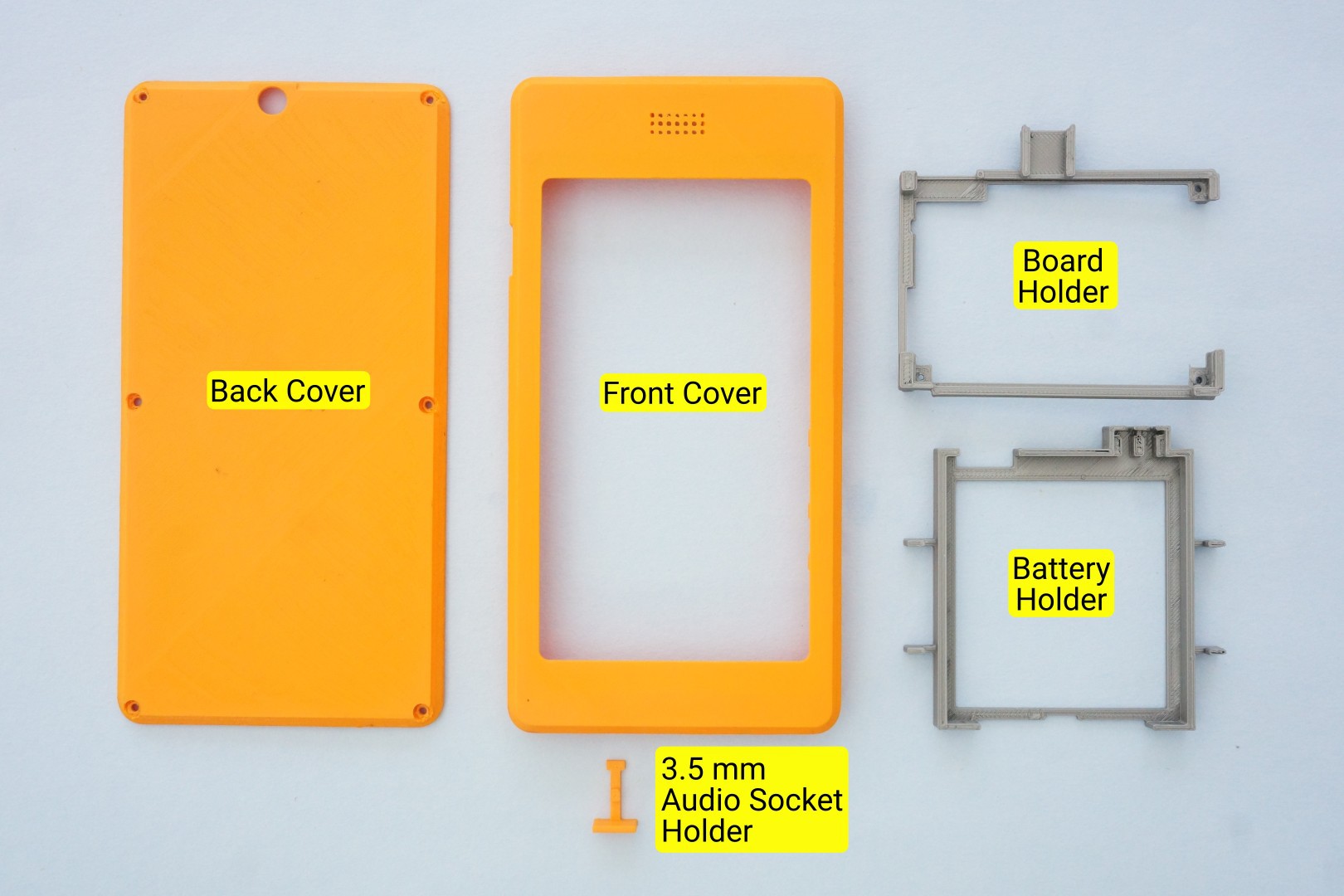
There are 5 separate 3D printed pieces in the design: the front cover, the back cover, a board holder, a battery holder, and a small part to support the audio jack. The front cover & back cover together make up the overall enclosure – what you’d generally call the “phone”.
The printed parts are pictured here:
The board holder needs to be printed with supports enabled; I use the option “Support touching build plate” on Slic3r. The rest can be printed without any special settings. Generally, I use 0.2 mm layer heights and the other defaults (20% infill). And of course, PLA filament.
For the sake of completeness, I should mention that that the orange parts pictured in this example were printed with a fine (0.25 mm) nozzle. ColorFabb nGen Orange was used for the externally visible parts. The board holder and battery holder are printed with ColorFabb PLA.
I don’t quite remember exact print times. The board holder and the battery holder take around 30-45 mins each at default speeds on my Prusa i3 MK2 Multimaterial printer – and printed with a single fiilament. The orange parts were printed with the fine nozzle, and ended up taking around 12 hours. With a 0.4mm nozzle, print times must be under six hours.
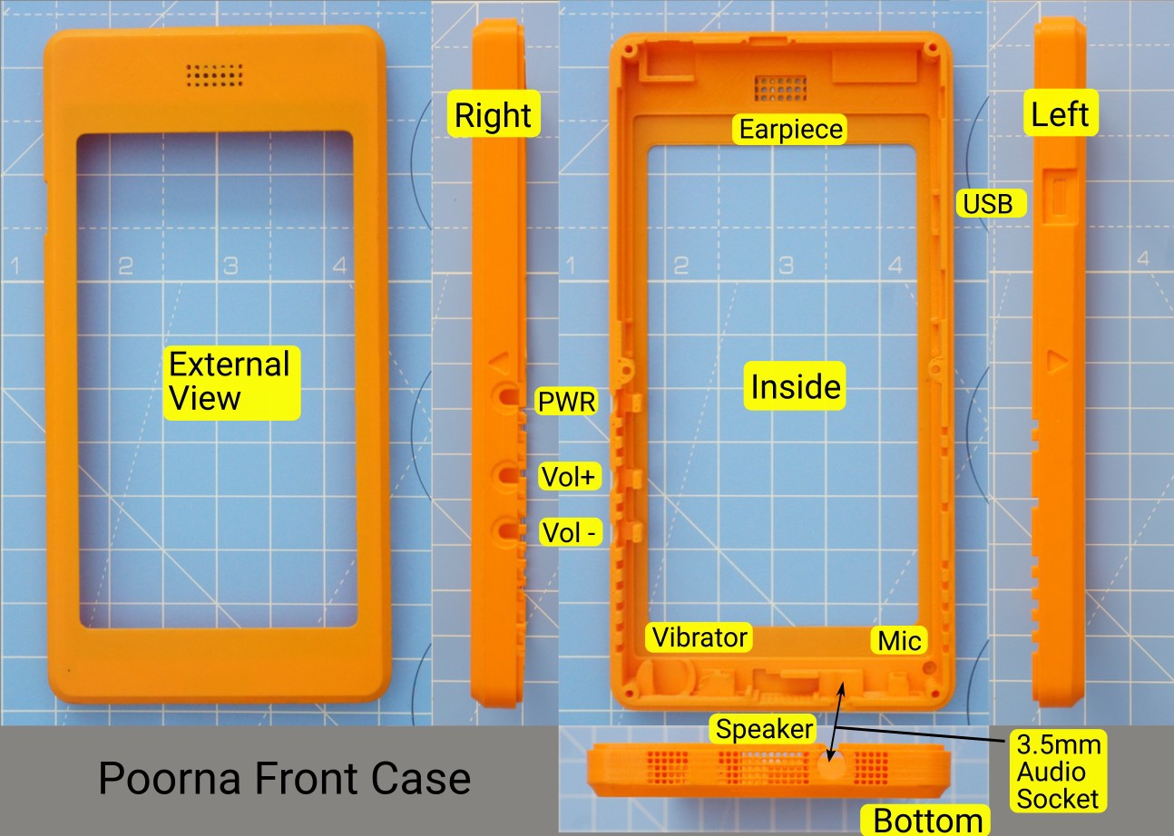
Let’s look at the design itself a bit. Important aspects of the front cover are labelled here:
Note the slots in the front cover for the display module, 3 push buttons, a vibrator, speaker, microphone and earpiece, and a 3.5 mm audio socket.
Why did we use standard push buttons? Because we can! Also, we wanted to keep away from specialized components (like dome switches, more PCBs, and so on), as much as we could.
The front face shows the earpiece grille. There is an oh-so-tiny hole for the microphone. The speaker is positioned at the center of the device, below the screen. There is a speaker grille in the front cover. The left and right parts of grille are faux – designer touches.
A hole for the USB connector is by the side.
The back cover, similarly looks like this:
The 8 MP autofocus camera shoots from the back. There is a hole in the rear cover corresponding to this. Six self-threading M2 screws are used to fasten the back & front case together – resulting in the complete unit.
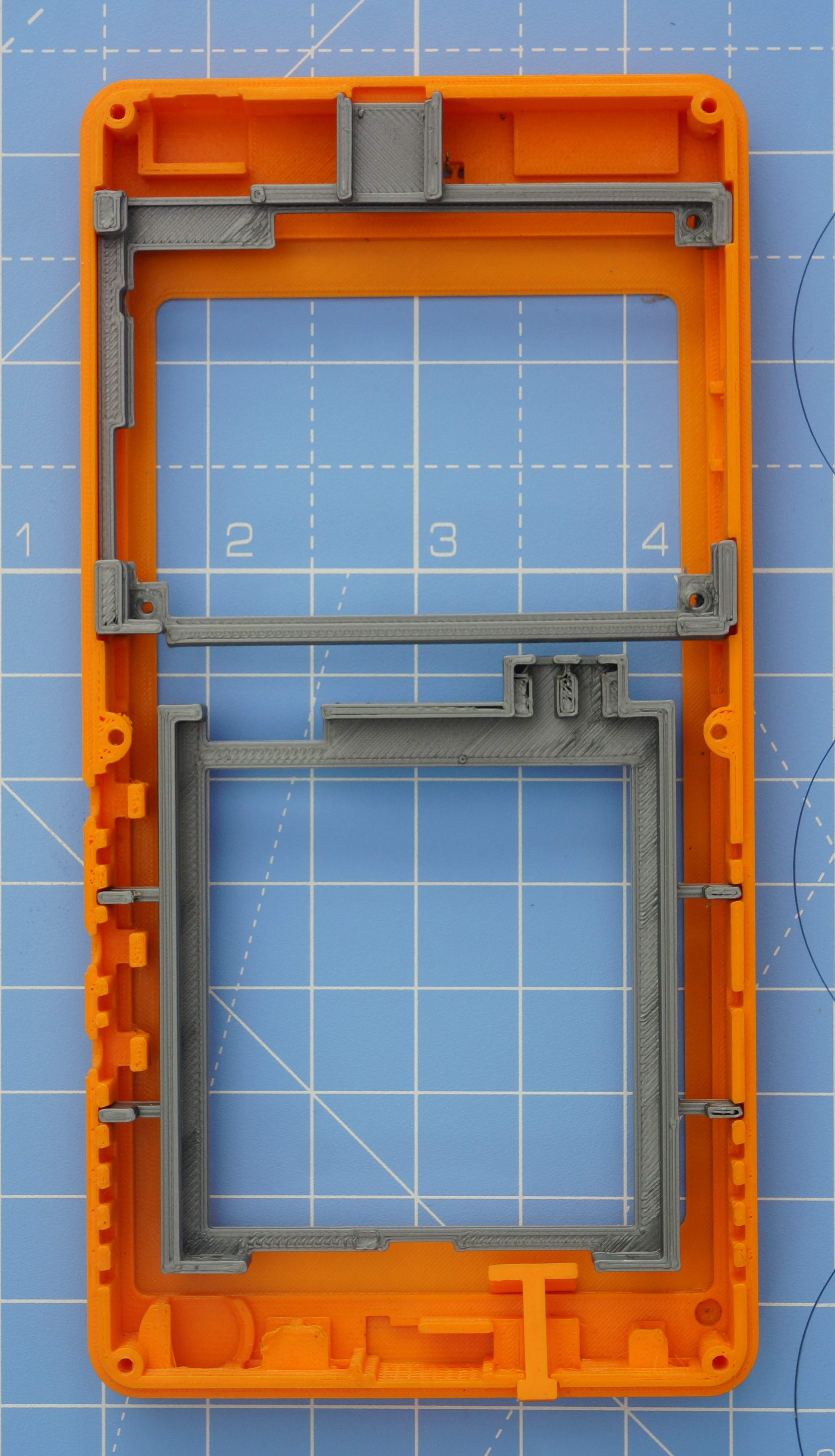
The front case has slots designed for the holders. The following picture shows how things sits together:
The overall dimensions of the fully assembled Poorna phone is 79.5 mm x 157 mm x 14.7 mm.
The total weight of the printed parts is about 50 grams. And the overall weight of everything put together – batteries included? About 200 grams.
Ok – enough talking. Let’s start putting together the thing, shall we?
Assembling the Display Module
Kite includes a 5” 720p display module with integrated 5 point capacitive touch panel, plus a display adapter board and a couple of flex cables, pictured below:
Mobile displays are “fast moving” items. Meaning, that they undergo frequent design changes. They can also go out of production rather quickly, and at inopportune times. There are no “long life” warranties associated with them. When longer life is a requirement, the common solution is to pick an “industrial” display. In general, industrial displays are bulky and generally not suitable to build a compact device.
To combat such uncertainties, we need a design that can change with times. We rely on 3D printing to make the phone, so that can take care of changes in physical dimensions. But what about the electronics, and interfacing?
KiteBoard includes a generic display connector to solve this problem. An intermediate display board adapts this generic connector to the specific display in use. A flex cable is used to connect the KiteBoard to the display board. Problem solved!
KiteBoard’s display connector natively supports MIPI DSI displays. Mobile displays use this standard extensively, so there is no need to do any fancy high speed signal conversions. The display board includes a couple of voltage regulators, and a level converter for the touch panel IC (which runs at 3.3V, as opposed to 1.8V for the KiteBoard). For the curious, the schematics of the display board are in kite-design-v01.zip.
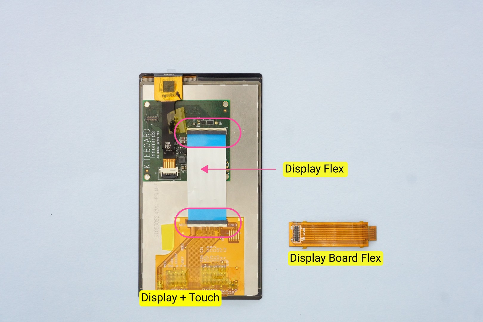
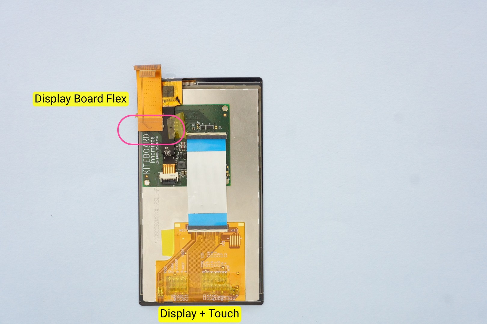
Putting together the display module takes a few simple steps, and doesn’t require any tools. First, align & place the display board over the display module. Then, connect the narrow flex cable of the display module to the corresponding connector on the display board. The flex cable is slightly longer, but it works well. The narrow flex cable corresponds to the touch panel (if you zoom in you’ll see the SDA, SCL labels…)
Next, use the display flex (it’s a 42 pin 0.5mm pitch FPC cable – as a quick hack we cut a commonly available 50 pin cable carefully to get this) to connect the wide flex cable on the display module to the corresponding connector on the display board. At each end, you need to open the white flap gently, insert the flex cable, and close the flap. It’s best to connect the flex on the display board first, and then connect the other side. Now, our setup looks like this:
Unlike the display flex, the Display Board flex is a custom FPC cable. It is a two layer flex cable, designed to carry impedance controlled signals with proper reference planes. Proper design of flex cables is important for carrying high speed signals. There are stiffeners over the connectors – this makes the ends sturdy.
In preparation of the next steps, connect The Display Board Flex cable onto its corresponding connector on the display board. Note that I have bent the flex cable a bit. This is useful to connect that end to the KiteBoard later (this will become clear in a few steps). This finishes the display module assembly. Our setup now looks like this:
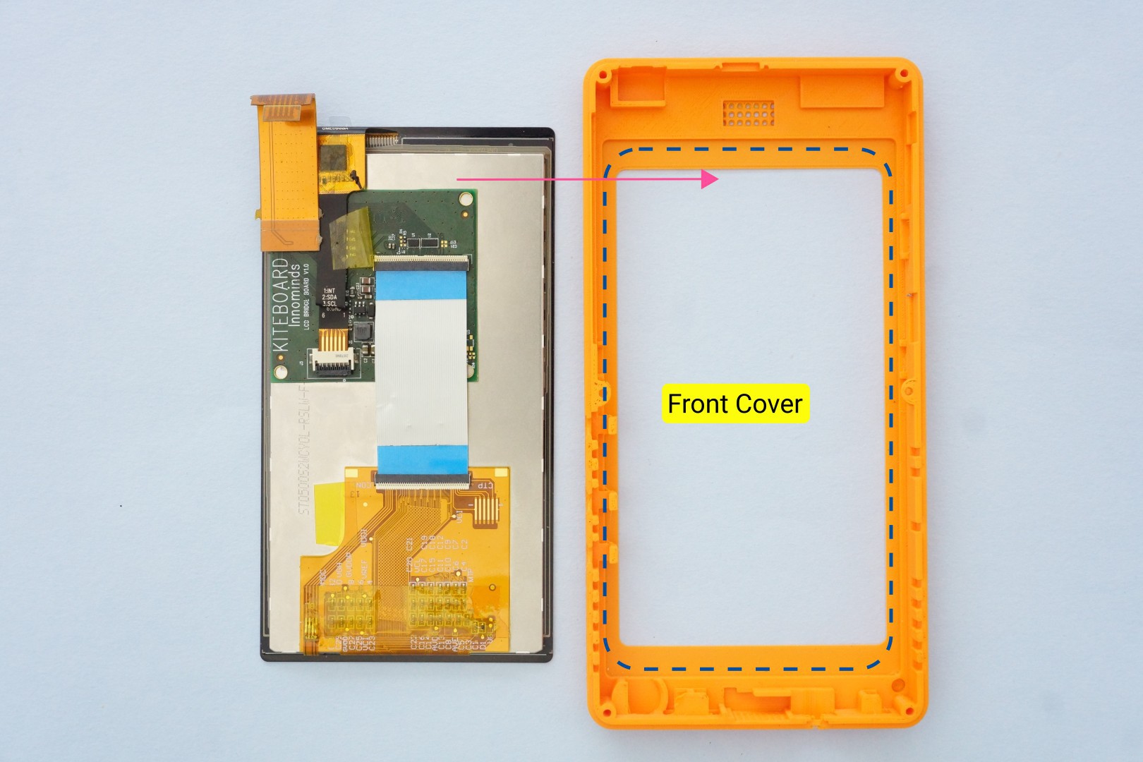
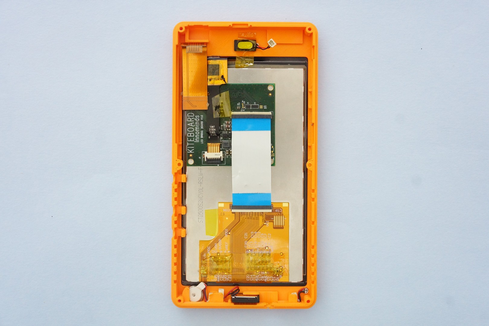
Time to install the display module assembly into the front case. Here are both of them, side by side.
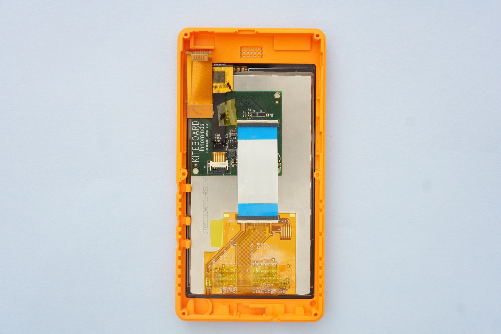
The display module sits nicely inside its slot, and snaps into place.
At this point, we are done with the display module. We will connect it later to KiteBoard.
Adding Audio & Buttons
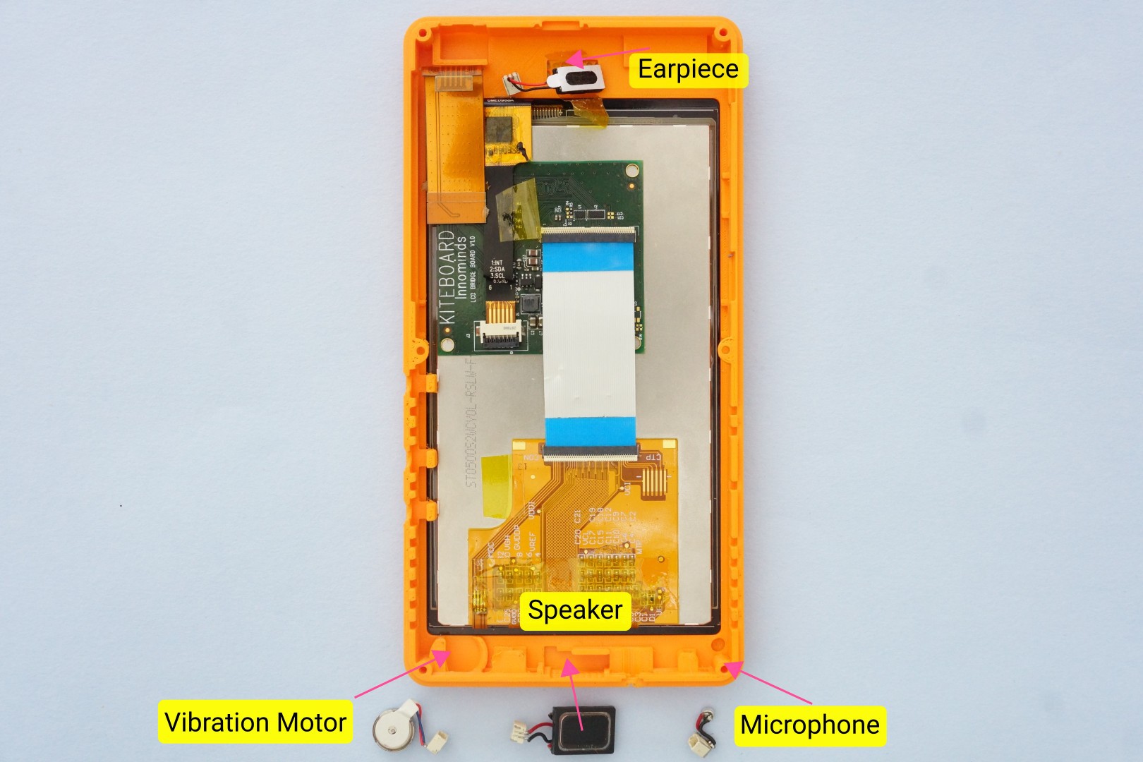
Next, let’s take the vibrator, speaker, microphone & earpiece and place them close to their final location.
As mentioned earlier, the front case has a slot for each one of the audio components. These components are small. Holders for the micro connectors (1mm pitch male shrouded headers) are designed into the front case to ensure that they are held in place.
There’s a small story around how we ended up choosing these connectors. In any particular build of Kite, we expect that these components won’t change much. However, a maker may want to customize other aspects – like the many back cover customizations that we have shown in our earlier video. To make it easier to connect/disconnect these audio components, we needed two pin connectors. Searching online got us a few possibilities, but we didn’t find anything that met our exact needs. Maybe we didn’t search hard enough. Luckily, we got 1mm pitch tiny board to wire connectors in the local market. No crimping required, no special tools. A single wire assembly looks like the below picture. These work reasonably well for now, but it’s an area that needs some improvement.
Coming back to the components… The vibrator, and the connector for it, is next inserted into its slot. Do the same for the speaker and the microphone.
The microphone is quite tiny. I generally use a small tweezer to put it in place. There is a small hole on the face of the front cover, through which audio is picked up by the microphone. This is visible in the design files. The hole is so tiny that it didn’t make sense to label it in the images.
The earpiece also sits nicely in the slot. The front face of the earpiece has a sticker that can be peeled out. This can be used to securely attach the earpiece to the front cover. As a temporary measure, I use a bit of tape to hold the earpiece in place.
Brains and More!
We are now ready to prepare the “brains” of the device – the KiteBoard.
KiteBoard has separate connectors for various interfaces. This makes it useful out-of-the box. These connectors cover all the areas of customization:
a display connector
two camera connectors
120 pin expansion connector
battery connector
vibrator connector (solder pads)
u.FL/IPX connectors – one each for GPS, WiFi/BT and 4G
KiteBoard also has a micro USB connector, a SIM card slot (microSIM form factor – push push type), and a micro SD card slot. KiteBoard is designed to be usable standalone. If you pop in a SIM card, connect the antennas, and supply power, then it will boot to Android directly. But that’s not something we will do right now.
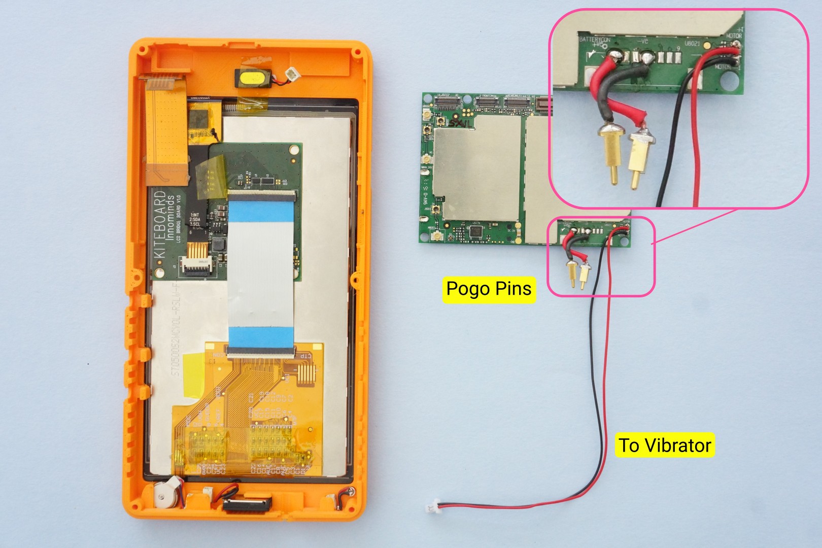
Let’s get the KiteBoard into the picture, and continue with the assembly. This step needs some soldering, shown in the picture below:
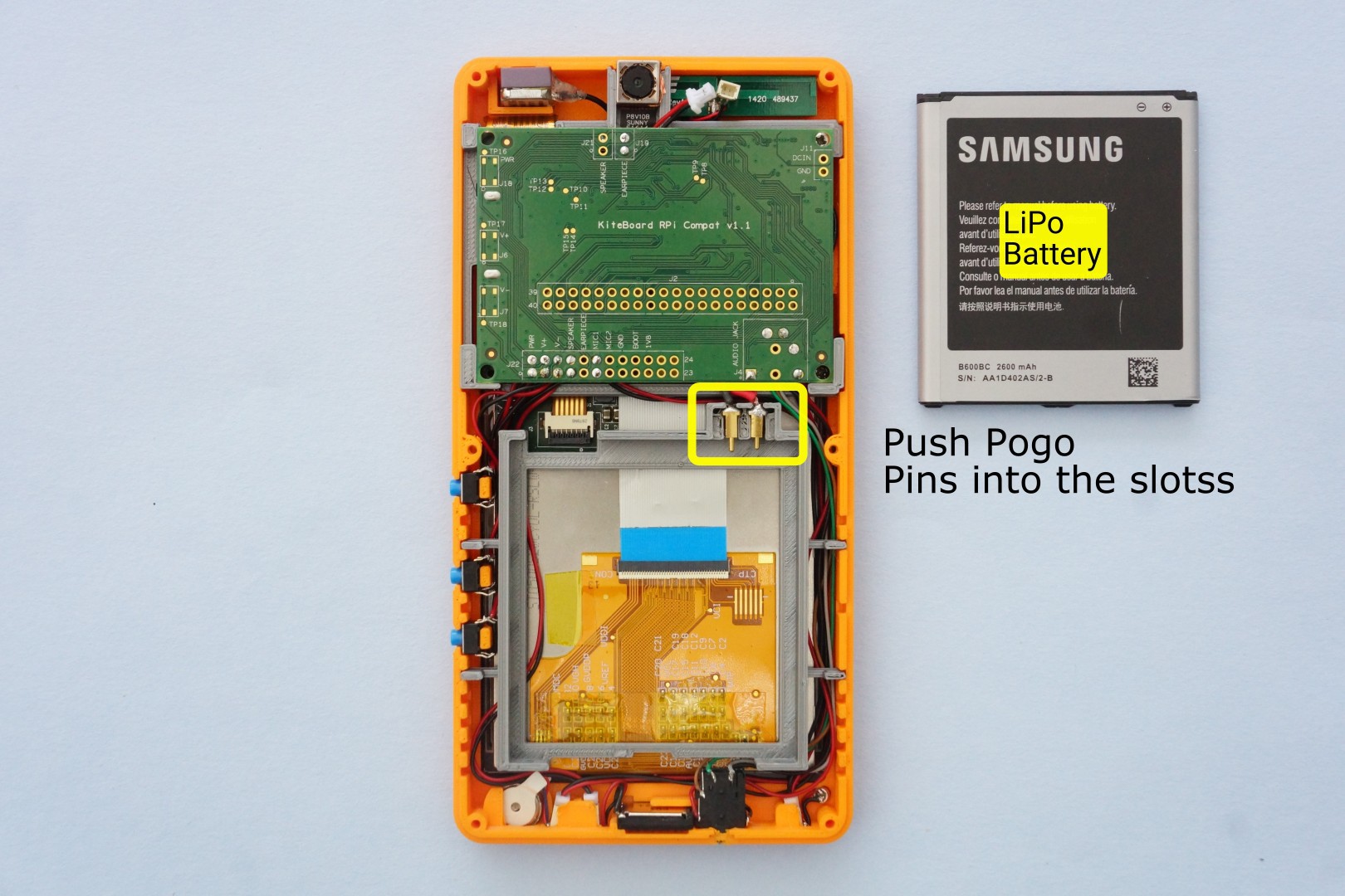
Using small pieces of wire, and a soldering iron, let’s connect the pogo pins to the battery connector. The two pogo pins will connect to the +ve and -ve terminals of the battery. These pogo pins will sit inside the battery holder, allowing us to swap batteries later.
The vibration motor pads are soldered to a long pair of wires connecting to a male micro connector.
Ideally, we shouldn’t need soldering on the main board. A design revision is required to achieve this.
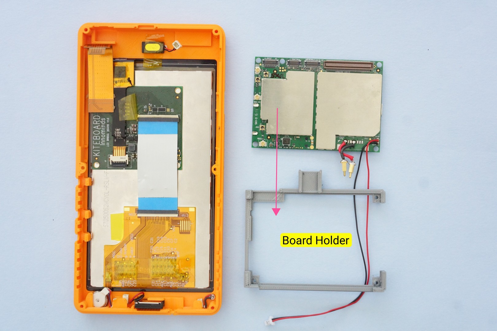
The prepared KiteBoard will sit in the 3D printed board holder. Let’s get that into the picture now.
Next, insert the KiteBoard into the board holder. Two screws (M2x5) keep the KiteBoard securely in place.
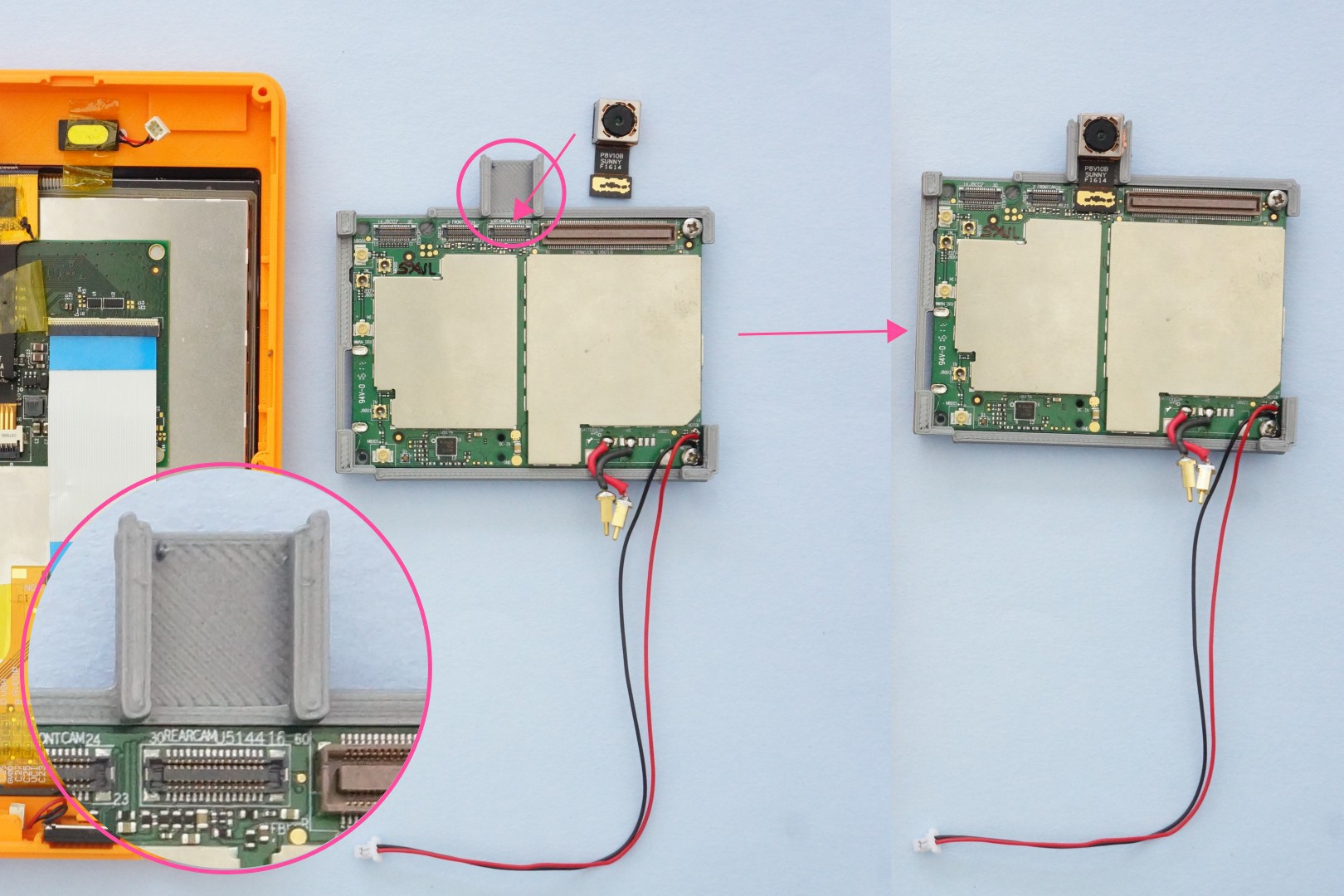
Kite includes an 8 MP autofocus camera module. The board holder has a slot designed for the camera module. The camera module sits inside the slot. The short flex cable is inserted into the corresponding camera connector on KiteBoard.
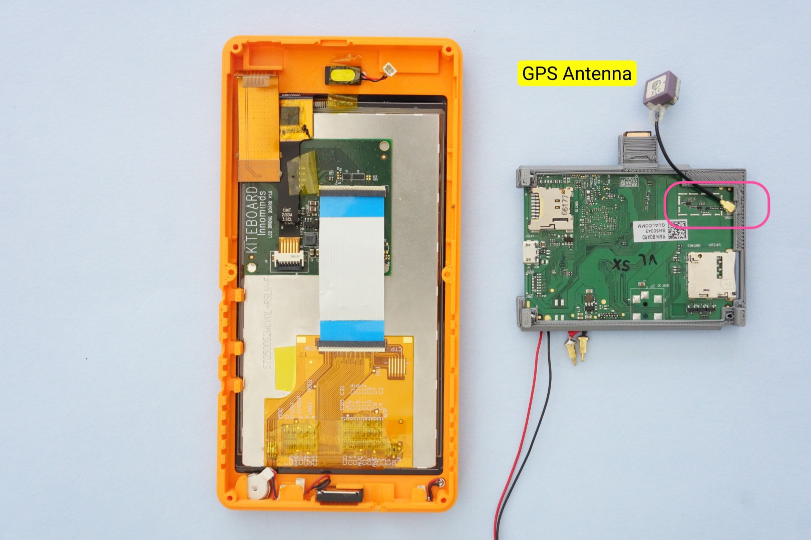
The GPS antenna connector is on the bottom side of the KiteBoard. The GPS antenna in the kit is Sanav’s D-10, a tiny ceramic GPS antenna. It comes with a 4cm long cable terminated with an IPX connector. The cable is slightly longer that what we needed, but we didn’t have any problems with it. We found that the antenna cable would twist & break. To compensate for this, we put a small blob of hot glue where the cable attaches to the antenna part. This provides mechanical stability, but doesn’t impact the antenna in any other way. The GPS antenna is connected to the uFL connector on the bottom side of the KiteBoard.
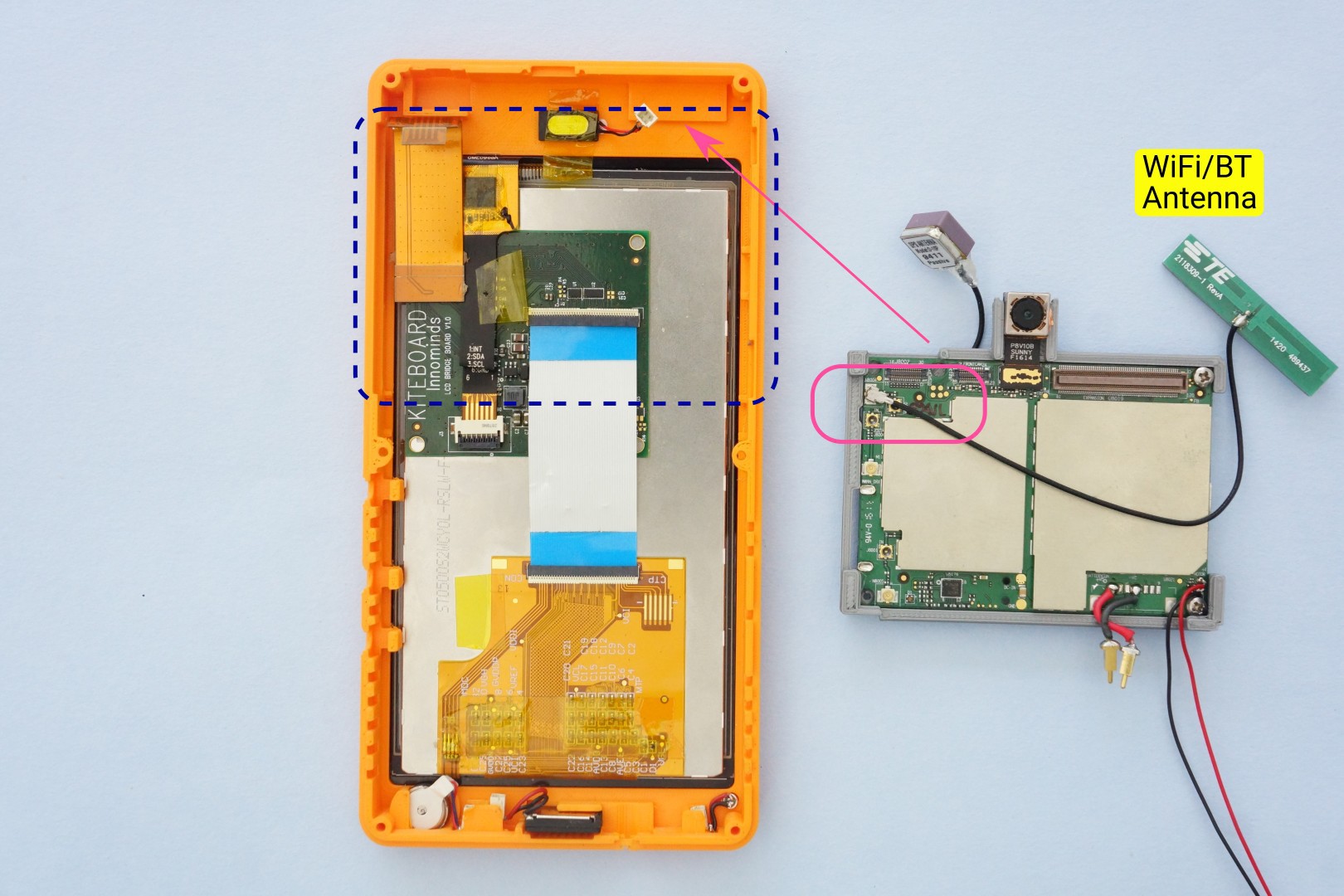
The WiFi/BT antenna (TE connectivity part no 2118309-1) is connected next – to another u.FL connector on the top side of the KiteBoard.. The cable is quite long, but nothing that won’t fit inside.
If you need to use a SD card, you will have to connect it to the board now. The case design doesn’t make the SD card slot usable from outside. I know - stupid of us to overlook this – but we’ll fix it eventually. At this time, the setup looks like the below picture. In the next step, the board holder will be placed into its slot in the front cover – so this is a good time to have a look at that as well.
The board holder is next placed into its slot in the front cover. While doing this, the GPS antenna and the WiFi/BT antenna are carefully placed in their positions. Note that the WiFi antenna cable is routed from the side. The connector for the earpiece must be accessible after this (it comes over the WiFi antenna, as shown in the picture below). We will need it later to connect the earpiece. With all this done, our table looks like this:
The display board’s flex can now be connected to the display connector on KiteBoard.
We’ve been assembling the kit for a while now, without seeing much results. Boring, right ? Now that the display module is connected to KiteBoard, is it possible to verify if it works? You bet. Connect a cable USB to the KiteBoard – with the other end connected to a laptop – and you should see the Kite logo on the display.
Good job! Things are fine at this stage. With the USB cable, it won’t boot to Android yet – but then good things in life come a bit slow…
It is very useful to be able to verify the display at this time. Imagine assembling the whole device & then figuring out that display does not work. If you saw the timelapse video, you would remember that the device is powered on only in the end. Powering ON the display in middle of the video would have killed the video… I added this verification step after I finished shooting the timelapse, hence the new background.
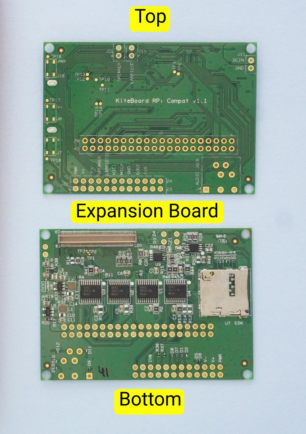
The expansion board stacks on the KiteBoard, mating to the 120 pin connector. The picture below shows both sides of the expansion board.
The expansion board makes the KiteBoard usable for everybody. It converts and exposes the platform I/O pins at a usable 3.3V level. 3.3V and 5V power are provided for user electronics. Platform audio capabilities are also made accessible by the expansion board. The expansion board is, in fact, the unsung hero of the whole modularity angle. And will remain so in this post; we're building the base model after all !
The bottom side of the expansion board has many components – mainly voltage regulators and level conversion circuitry. Also a micro SIM connector (this is the second SIM card), push push type. The top side is designed such that components need not be mounted on it, when used in a phone style case.
The expansion board has a few significant footprints, all using standard 0.1 inch spacing:
a 40 pin Raspberry Pi HAT compatible connector. This exposes the platform pins, after level conversion to 3.3V. KiteBoard runs at 1.8V, so conversion is required. The level converters also provide useful ESD protection.
a 24 pin Audio & button connector, with useful pair of pads for
Power button
Volume up button
Volume down button
Speaker
Earpiece
Microphone
The rest of the pads provide ground, 1.8V pads, boot options (for future use), and a few I/O pins at 1.8V logic level. The speaker & earpiece signals are also routed to another location close to the 120 pin connector. This was done to simplify wiring.
5V DC power. This can be used to power the KiteBoard using an external power source. The KiteBoard can take power from three sources: battery, USB, and DC(5V). We won’t use the 5V option in this build.
Standard 3.5 mm audio socket (Digikey part number SJ-43515TS)
A bit about Raspberry Pi compatibility before we proceed further. KiteBoard is not based on the same SoC as the Raspberry Pi, and works at 1.8V level, so we can’t be 100% compatible with the Raspberry Pi. That said, most shields that use I2C, 3.3 & 5V power, SPI and UART interfaces will work. I2S can be made to work with some wiring from the display board, but that’s not straightforward. We are planning to fix this in the next revision of the KiteBoard.
Connecting Audio & Buttons
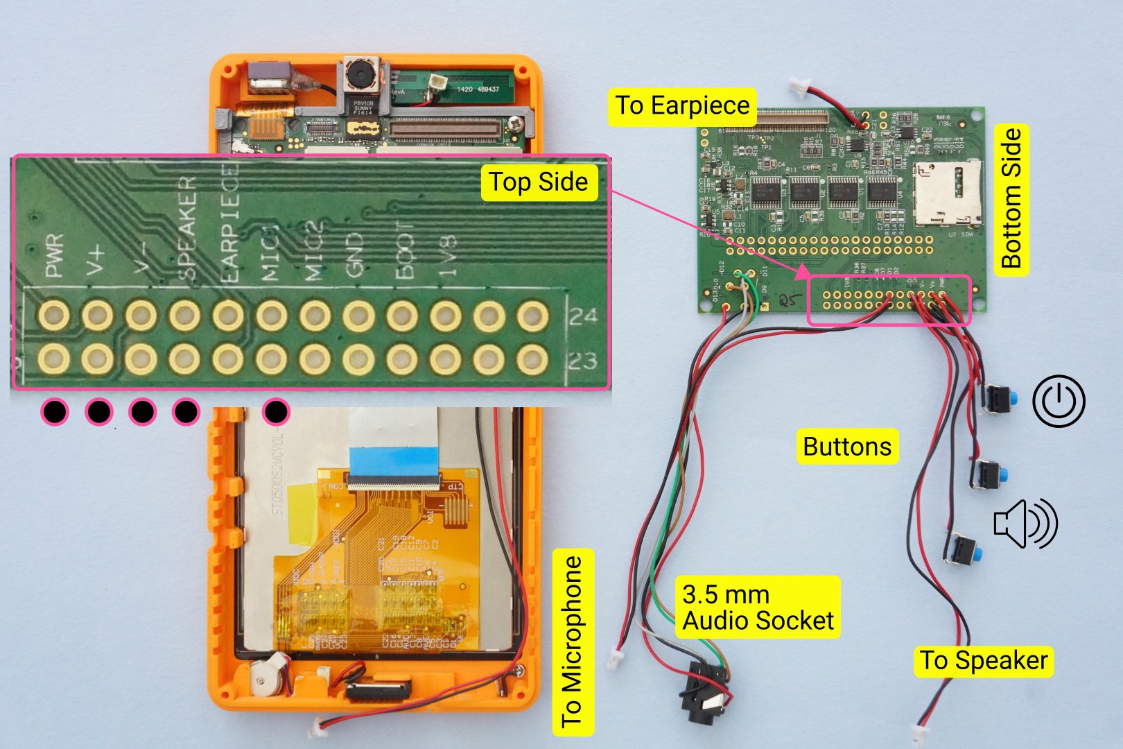
Soldering is needed for the audio components. We need to wire a few parts:
Power button (2 wires)
Volume up button (2 wires)
Volume down button (2 wires)
Speaker (2 wires)
Microphone (2 wires)
Audio socket (5 wires)
Earpiece (2 wires)
The picture below shows the wiring in detail. Note that the wires are routed from the bottom side.
If we flip over the expansion board into the orientation required for the next step, the setup will look like this:
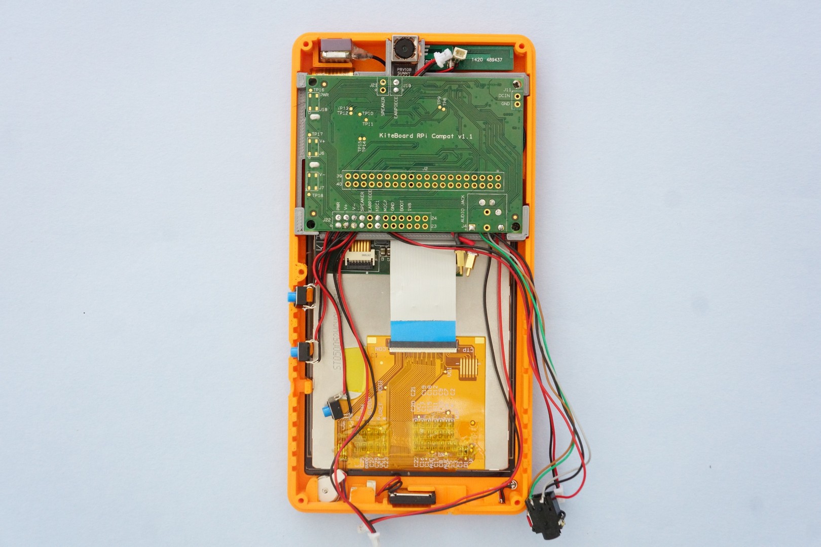
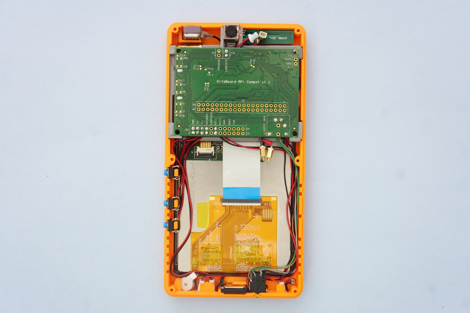
The expansion board can now be mated with the KiteBoard. The board holder has a slot for the expansion board. The expansion board sits nicely in this slot.
Next, insert the push buttons into their slots, plus connect the vibrator, speaker, and microphone. Note that the connectors for the audio parts are inserted sideways. Finally, insert the wired audio socket in its designated slot. After routing all the wires closer to the case, we end up with an arrangement similar to the following picture.
Battery Matters
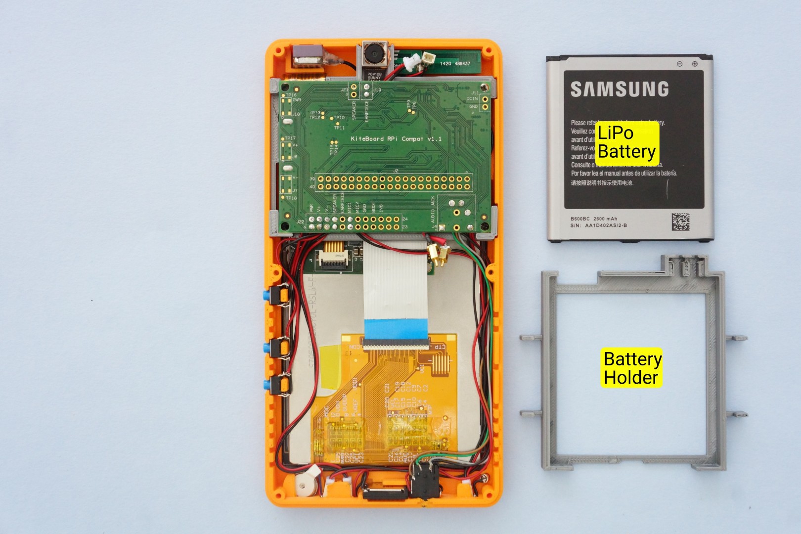
KiteBoard works with standard Li-Poly batteries. Sourcing compact standardized batteries (apart from some standards like BL-5C) is a pain – folks building products generally need to customize batteries to their requirements. Luckily, off the shelf replaceable batteries are available for various phones. We prefer replaceable batteries, as these can be swapped with a minimum of fuss. I found a 2600 mAh battery for various Samsung phones – and purchased it from an online store.
To keep the battery in place, we designed a battery holder, which is 3D printed. The battery holder has two slots for the pogo pins. When the battery is inserted into the slot, the pogo pins make firm contact.
The battery holder is designed to fit snugly inside the front case. The front case has “ridges”. The battery holder has fins that match & slide inside these ridges. The battery holder sits in the front case, as shown below. With the battery holder in place, the pogo pins can then be placed in their designated slots. Carefully note the + and – pins. These need to match the battery.
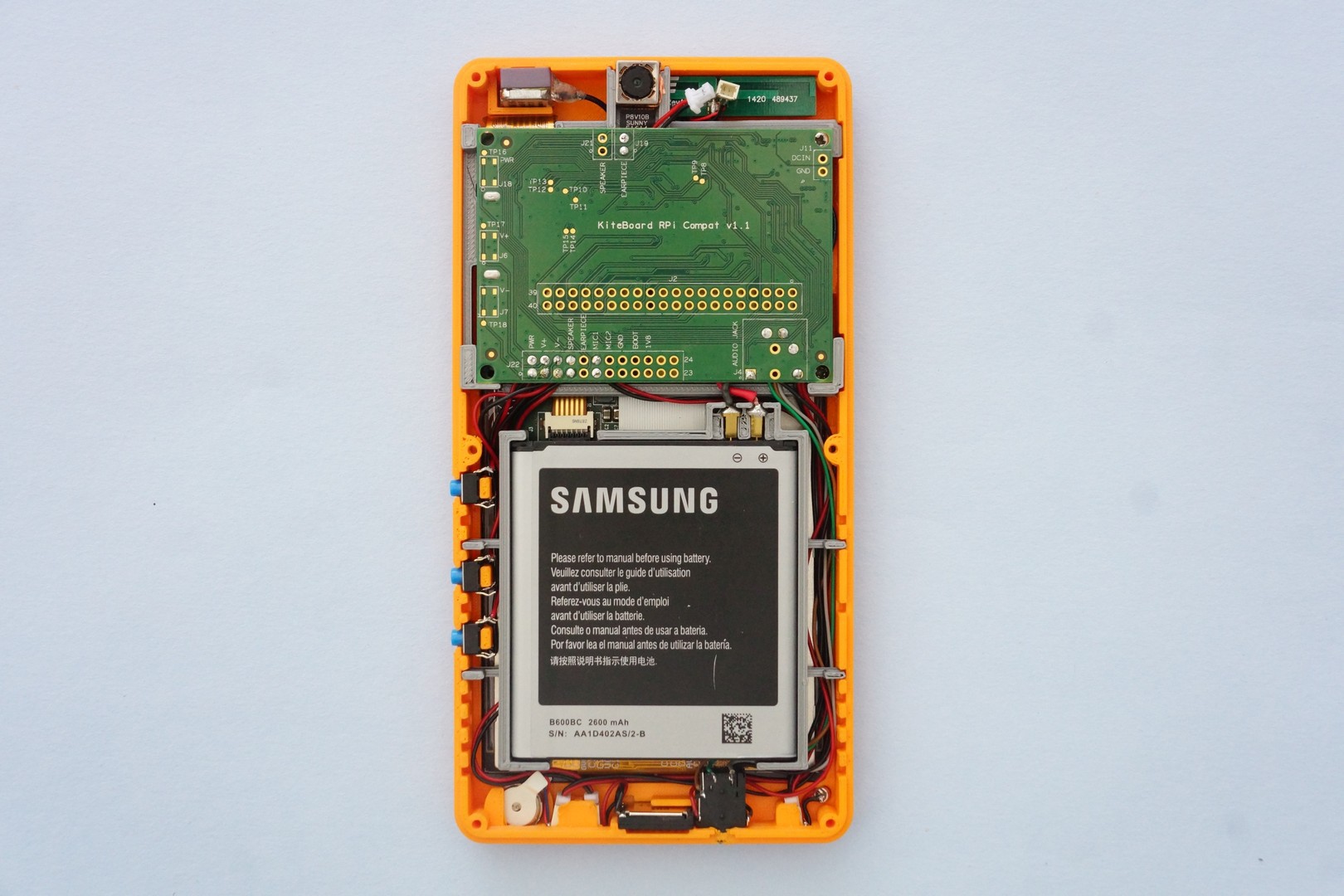
Next, lets insert the battery in the battery holder. The pogo pins will nicely hold the battery in place.
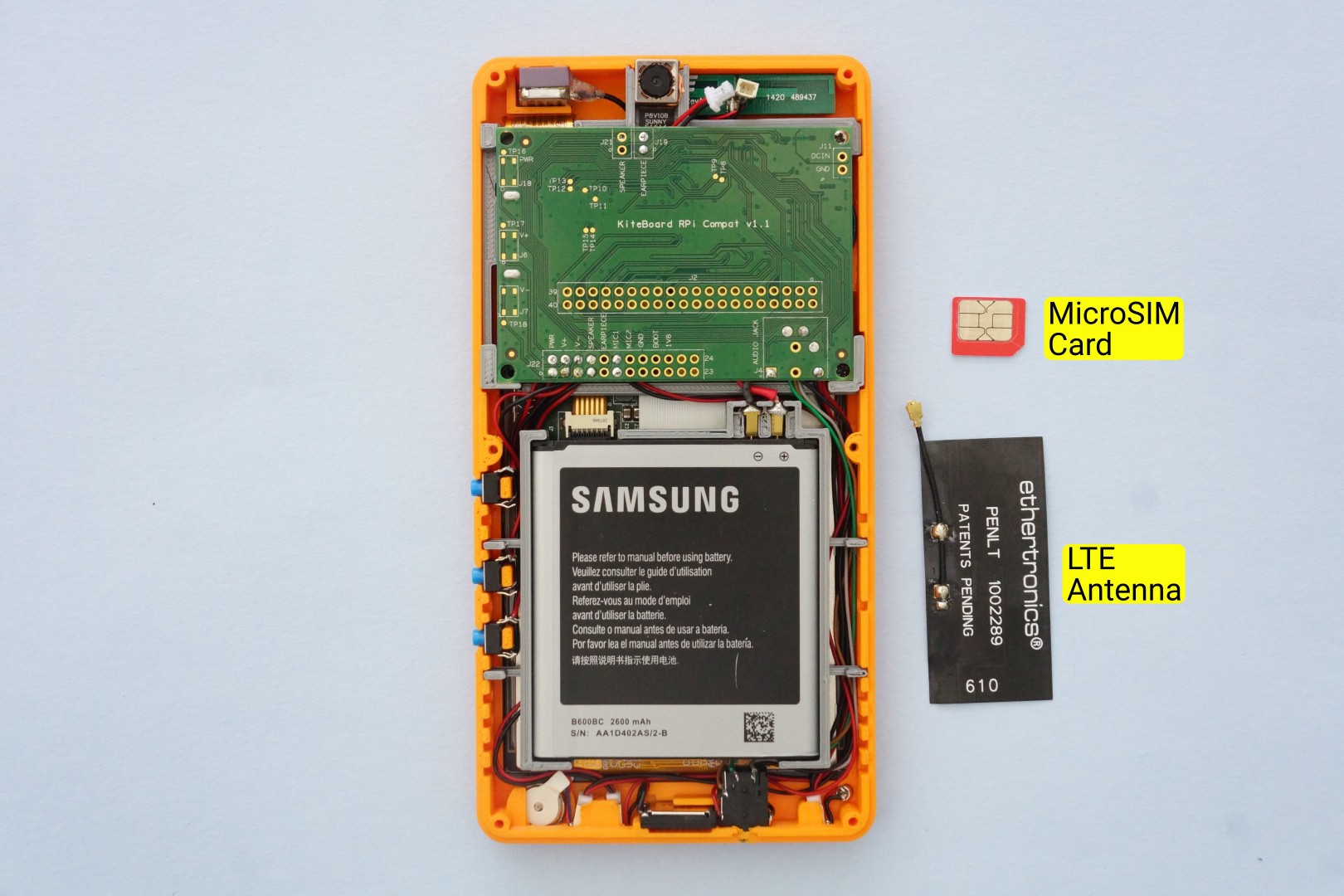
Let's get on the Network!
To get on a network, we need a SIM card and an LTE antenna. KiteBoard supports two SIM cards. The second SIM card is routed & made available on the expansion board – on the bottom side.
The LTE antenna we have are using for now is a penta-band flex antenna from Ethertronics (P/N 1002289). This supports all the LTE, 3G and 2G bands supported by KiteBoard. It’s an off the shelf part. Plus it’s available in a single quantity in DigiKey. All good reasons to use it in the kit!
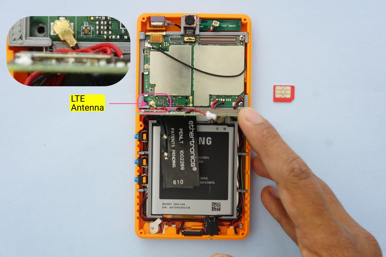
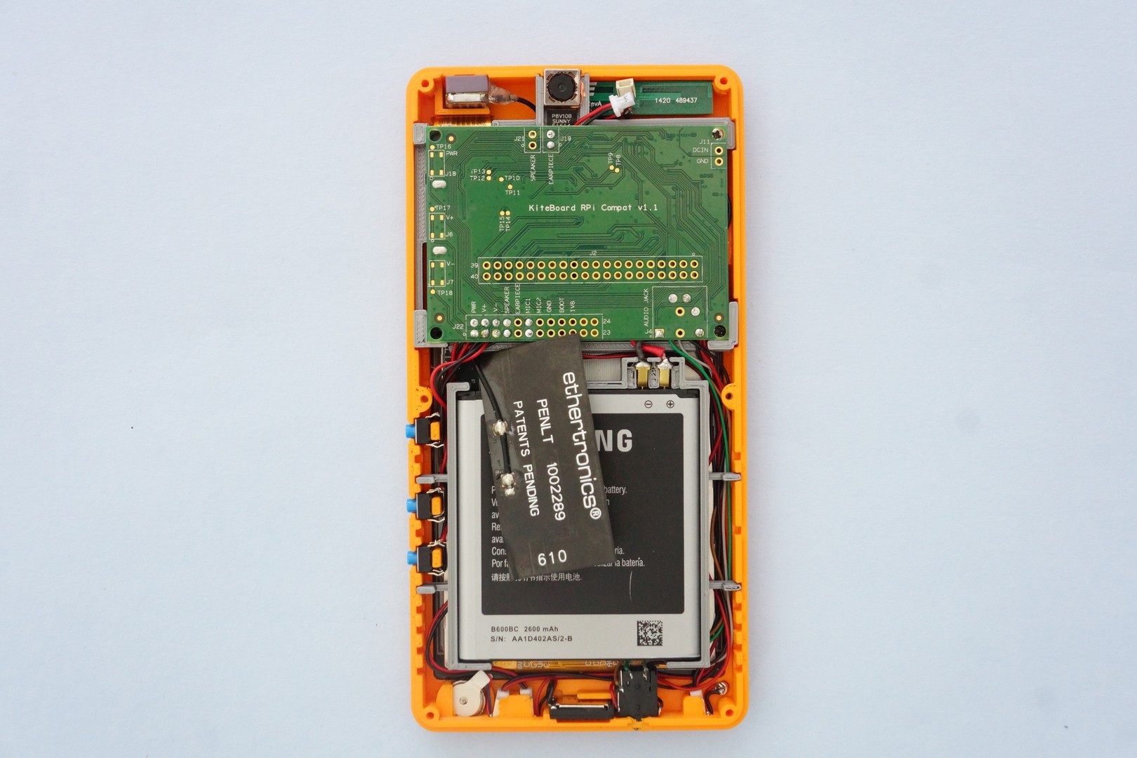
The LTE antenna connector is on the KiteBoard. With the expansion board plugged in, it is not accessible. To plug in the antenna, we unplug the expansion board. All the wiring stays in place. We can now connect the LTE antenna. The antenna sits on the battery, and connects to the KiteBoard. The antenna cable is quite short, but that’s not a problem for now.
Next, we insert the SIM card into the microSIM connector on the bottom side of the expansion board. It’s a push push type connector. Feel the satisfying click as you push it in…
When show the phone, folks generally ask me – “where do I insert the SIM card?”. We designed the case to have the SIM card completely inside, as we don’t expect our users change SIM cards often. This simplifies the enclosure design.
We can now connect back the expansion board to the KiteBoard again. The antenna appears to float in space.
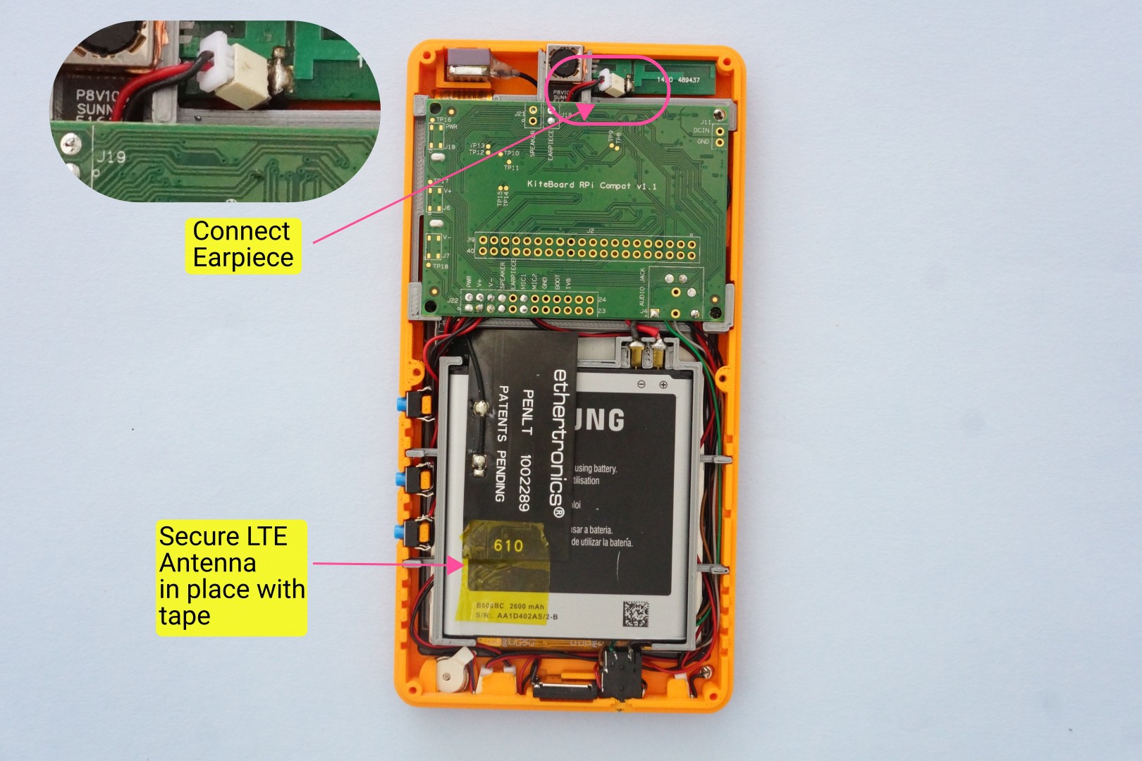
There’s nothing that a bit of tape can’t fix – secure the antenna to the battery with a bit of tape. This solution isn’t ideal - there is still a slight bend on the antenna.
The antenna comes with adhesive backing, and is intended to be securely pasted in place. Sticking the antenna on the battery would deviate from the concept of having a swappable battery. A complete solution to this will require customizing the cable, and some more work to decide a reasonable place for it – that’s work-in-progress. For now, a bit of tape works. Let’s connect the earpiece as well.
Time to close the back cover & complete Poorna. We’ll need a screw driver, and six M2x9 screws. The 3D printed parts include a small piece that helps keep the audio socket in place. We don’t realize this, but pushing an audio jack inside the socket results in a considerable amount of force. This piece is designed such that audio socket stays in place securely. Let’s place this part in its place.
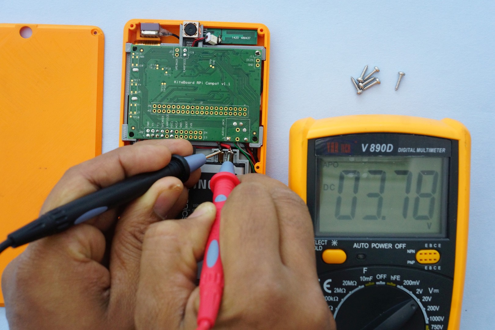
Are we ready to close the cover now? Almost. We’ll do one last check with a multimeter – ensuring that the pogo pins are making contact, and that the battery is sufficiently charged. The battery shows 3.78 volts (more than 3.6 is generally enough), so we are ready to go!
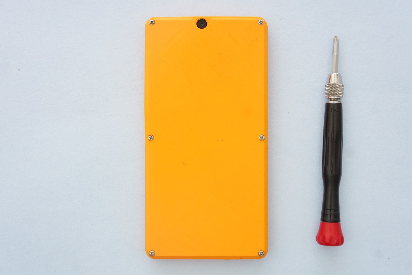
Now we place the back cover over the front cover. There are “lips” on the front cover to make sure the back cover sits nicely. Use the screw driver to put in all the screws. And then, drive the screws in all the way! Done with the screwdriver! We take a moment to admire what we have built.
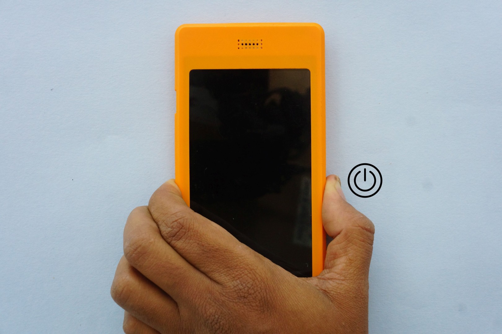
Showtime! Press & hold till you feel the vibrator announcing that the phone is coming alive!
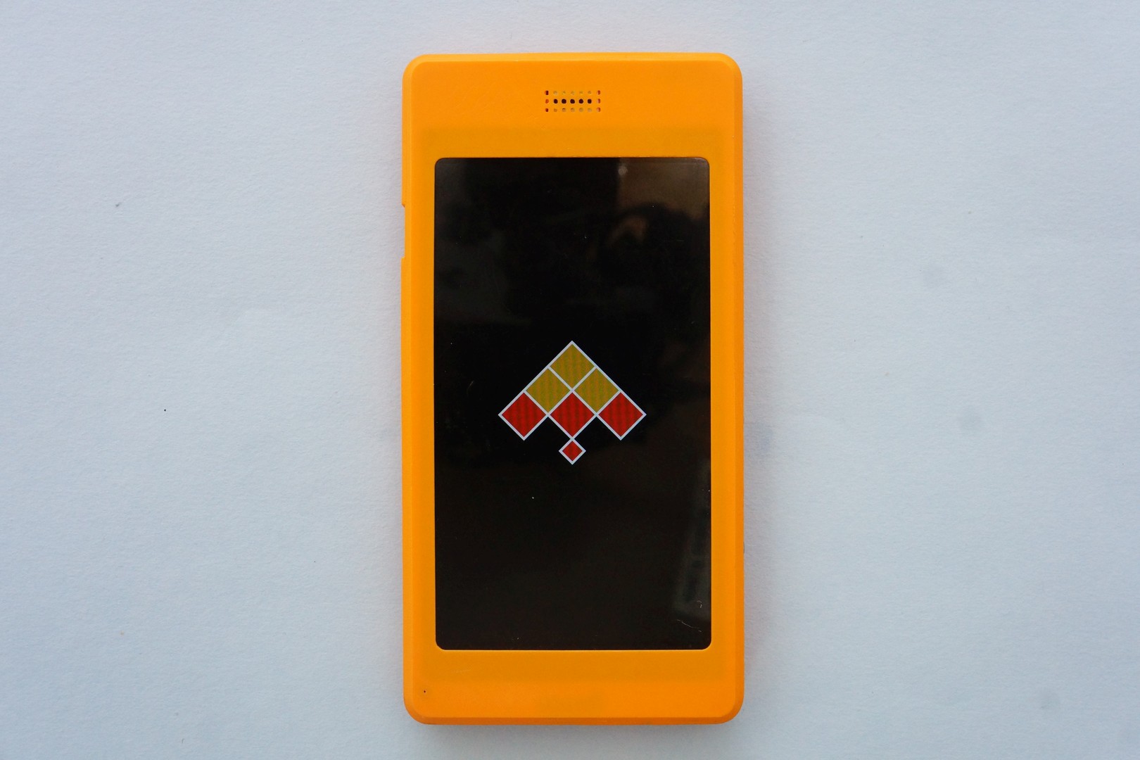
Almost immediately, you’ll see the splash screen. Yahoo!
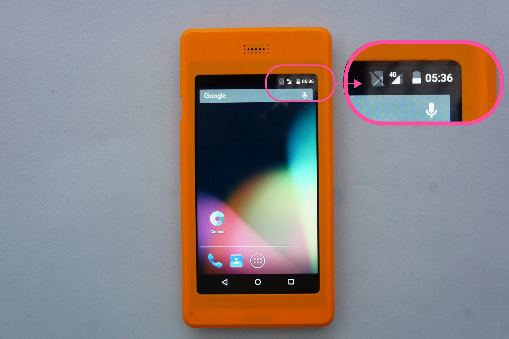
The phone will boot to the lock screen. Unlock the screen. Verify that you’re connected to 4G. That’s it, we are done. Enjoy android apps on Poorna, your fully custom-built phone. The full functionality of the SIM is available: data, voice calls & SMS.
Thanks for reading this far. Do remember that this is just the beginning. I have barely scratched the surface. Kite is capable of much more!
My first post on hackaday! I am excited to start this; my first project here...
Few folks (and I thank them for their interest in the project!) are asking me, "where are all the documentation & stuff about this project?". I am telling them, "I am adding it". (Yes, I am adding things - just had a good fight adding the component list. For some weird reason, I am unable to keep the list in the order I want -- the site seems to rearrange it according to it's own wish. Anyone knows why ?)
It may look that I made this project "public " too quickly - without adding adequate details. I'd like to believe that there is a method behind my madness (is there - hmm? ) . Documenting a project like this in one shot is a lot of work. I'd rather have digestible chunks uploaded in phases. But that's just me.
I do know that hackers & makers would love to see the details, not just a slick video (patting myself on the back here - I'd like to hear any comments about the video too!). My request for a few days - please bear with me while I make the details available in phases.
 Shree Kumar

 Now, you can install the AndroidVNC client (It’s ancient, but it works) using FDroid. The server is localhost:5901, that’s all you need to know. After the VNC client connects, you may use the X desktop. The X environment can is functional, but can take a bit of getting used to. In any case, you can double click on the desktop & start a terminal.
Inside the terminal, install the Arduino IDE.
Now, you can install the AndroidVNC client (It’s ancient, but it works) using FDroid. The server is localhost:5901, that’s all you need to know. After the VNC client connects, you may use the X desktop. The X environment can is functional, but can take a bit of getting used to. In any case, you can double click on the desktop & start a terminal.
Inside the terminal, install the Arduino IDE. 


 At this point, we have checked the hardware. It is fun to run the other examples too. I like
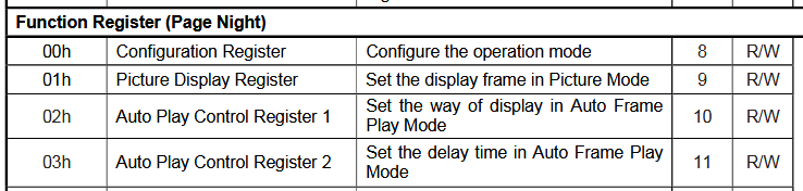

 This last exercise gave me a lot of confidence - if the cut matches the picture, then the print must come right... After half an hour of printing, I get the part: