gamaral
Replaced resistor used to power the flux circuit with a 3v3 SMD regulator that fit the resistor's footprint. The regulator now powers both the flux circuit IC and the ESP8266 module.
GPIO2 and GPIO0 in the ESP8266 module are used to toggle the flux circuit and keep state respectively. Using custom firmware, GPIO2 is pulled low for half a second when we need to toggle the flux circuit. This is accomplished by connecting to the ESP module via TCP and sending one of the following commands:
TIME CIRCUIT ON
TIME CIRCUIT OFF
When the flux circuit fluxes, the negative side of the LED's is pulled low, I hoked up GPIO0 to the negative side of an LED and made it interrupt on falling edge. When the interrupt is triggered I set the state to fluxing, I then start or restart a timer that will set the state back to off after a second. If the time circuit is turned off, then the timer will expire and that's how we keep state.
Just in case it wasn't obvious, we need to know if the time circuit is on or off so that we don't toggle it off when we want it to be on by mistake.

 Chris
Chris
 DIY GUY Chris
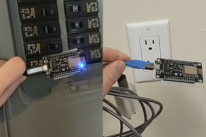
 ThinkLearnDo