 koswix
I've been planning a CNC build for years now, but finally I'm in a position to make it a reality.
A lot of design ideas have been considered, but ultimately the final choice is down to available materials, tools and space.
I've split the design into three major areas: frame, power transmission and control electronics. The current design is based on a welded steel frame, SBR16 linear slides and threaded rod for movement, and TB6600 stepper drivers being commanded from GRBL.
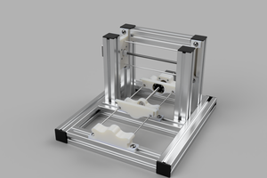
I'm hoping to start welding up the frame this afternoon. The attached rendering is a very rough plan of what the machine will look like – so far the only accurate part of the model is the frame dimensions. Other parts have either been simplified or omitted at this stage. I'm going for a very modular build, where components can be changed out or upgraded as funds permit. So although my initial build is going to use stainless steel threaded rod, later on I'll upgrade this to ACME rod with a proper ball screw.
So here it is: The Cheap n' Nasty Cutting Machine.
I've done some very basic finite element analyses on the steel box section and found that deflections should be within acceptable ranges -with a 30kg load and a 3Nm torque on the bottom frame, the maximum deflection is 0.03mm with the frame only supported at each end. The frame will have more supports than that (at least 3 feet per edge), and the total loading shouldn't be anywhere near 30kg!. Swiching to Aluminium would increase that deflection by a factor of 3.
Once concern is the mass of the gantry. Making the gantry from steel means there's a fair old bit of weight for the X axis stepper motor to shift. Fag packet calculations put the the steel gantry, without Z axis or cutter head, at 6.7kg. I might use aluminium section for the gantry (2.4kg), further thought required here though as an aluminium gantry would have to be bolted together (yay, adjustable for squareness!) and less rigid than a welded solution (boo, less capable of keeping its squareness).
FEA results: https://www.youtube.com/watch?v=7q1q4ejgPcE&feature=youtu.be
 Not much to report at present, real life has been getting in the way again. But the stepper drivers I ordered from China have finally turned up, and I had a chance last night to play with them.


 ing to use a desktop PC with a parallel port to control it all. Putting a force air cooled PC in a milling environment just doesn't seem that sensible, although I am considering a sound-reducing enclosure for the mill so we'll see. I think I'm going to push ahead with GRBL to start with, and move over to LinuxCNC once I've enclosed the mill.
 s better…) and ready to be welded. Was hoping to get that done today, but ran out of time. I've never welded anything before, so I did get a chance to do some practice welds today and it went pretty well!
 Current thinking is to use a bolt-on system for the gantry, so that it can be adjusted for squareness once all the other bits are in place. Not sure if this is a good idea or not yet.


 Myles Eftos
 Ossum
Ossum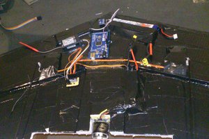
 cb22
cb22
 Joseph Marlin
MakeBlock XY plotter kit transformation
MakeBlock XY plotter is really good thing to use for engraving and laser cutting because
it has bigger sizes comparing to DIY kit. 31 X 39 cm (is quite a lot)
As far as we know there is a laser kit for MakeBlock but we did not try it. If anyone has
an experience, please share with us!