Close
0%
0%

Arduino ST4 telescope control

Telescope GOTO and autoguiding through ST-4 with an arduino

Similar projects worth following
The purpose of this project is to connect a telescope to a computer through the mount guide port (ST-4 port) using an arduino in order to cheaply add GOTO and autoguiding capabilities.

The ST-4 Port is easy to add to "low cost" motorized mounts like the EQ4 or EQ5, and the operation requires minimal modification to your shiny mount.

Hardest part is the code (Arduino sketch ~120 lines and ASCOM driver ~2600 lines), but I already wrote it for you :-)

Basically, you need to build the USB-ST4 interface described in the github project page and modify your control pad like explained here if it doesn't have an ST4 port.

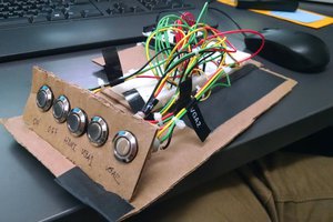
Modifying the control pad means soldering and wiring an RJ12 socket to the pad buttons.

Once the hardware is done, you will need to install the ASCOM platform and the driver.

After this you can use a software like the open source stellarium to play with your telescope or PHD for astrophotography.

More details are available on the github project page.

Here is a small guide to use it with stellarium.

Sample video of the telescope moving:

  • 1 × Arduino For interfacing with USB
  • 1 × TLP521-4 optocoupler In order to isolate the arduino from the autoguide port
  • 2 × RJ12 socket 1 if your mount already has an ST4 port
  • 1 × RJ12 straight cable To connect the adapter and the mount
  • 1 × A case for the adapter Excepted if you prefer to see the bare electronics :-)

View all 6 components

View project log

Enjoy this project?

Share

Discussions

nevyoung wrote 10/03/2022 at 13:47 point

NOTE: I eventually found a solution to this problem (see below), but here is the scenario:

My implementation for a telescope autoguider uses a standalone Atmega328. I communicate with it via an FT232 USB-Serial converter board. I can download an the Arduino Autoguider program to the chip.  I can download Blink to the standalone 328 - it works just fine.

I am using an an autoguiding program called PHD2. PHD2 cannot communicate with the Arduino Autoguider because the computer only sees the FT232 board.

If I instead programmed the Arduino Autoguider program into an UNO board, (which means that I am now using the UNO’s onboard USB-Serial converter), the Arduino Autoguider program works just fine. The is no apparent clash between the autoguider and the FT232 drivers.

My question was: Should it be possible to communicate with the autoguider on the standalone Atmega328 via the FT232?

While I was writing up this post on the Arduino forum, I was prompted to look at this post “Standalone ATMEGA328 with CP2102 USB-Serial Converter”, which had not cropped up in my previous searches.

@iceeyes1992 – at the Arduino forum had the exact solution.

“i had the same problem.i had a atmega328p and a cp2102 with dtr pin.i tried different ways.after spend of 3 days i found the solution.

after burn bootloader to raw atmega328p with arduino as isp or usbasp you must choose only arduino pro or pro mini as your board in tools menu and one of the avr isp or arduino as isp or avr isp mkll as programmer.and then upload your sketch.that’s it.”

NOTE: I had burned a bootloader onto the Atmega328 earlier via the UNO board. And then had uploaded the Arduino Autoguider sketch, probably with Board: Arduino UNO selected – I think. Uploading worked fine, but PHD2 did not see the autoguider.The COM port was 4 and called something like “Serial Converter” when I was expecting to see “ArduinoST4 telescope driver (ASCOM)”.

So – following the advice from @iceeyes – I reconnected to the standalone ATmega through the FTP232 converter. I simply selected Board: “Arduino Pro or Pro Mini”. An extra field opens up – Processor, from where I selected the “Atmega328P (5V, 16Mhz)”. I then uploaded the Autoguider program again.

The PHD2 guiding program then saw the “ArduinoST4 telescope driver (ASCOM)” in the Mount selection list in PHD2. Success! Guiding is working fine.

(Note: PHD2 will not connect to the autoguider after the Arduino IDE has been connected to the 328. Messages received were COM4 denied or other times response too slow. I had to unplug the autoguider, then plug it in again. )

Bottom line – for standalone Atmega328 through USB-Serial converter, Select Arduino pro or pro mini as your board.

PS: I might be mistaken about some of the sequences, but became very confused while sorting out the problem over several days.

  Are you sure? yes | no

nevyoung wrote 09/19/2022 at 11:14 point

Hi Kevin - hope you are still available to answer my question.
Perhaps I am trying to be too clever because I decided to use an ATmega328 chip on its own for space saving reasons. I can get the autoguider code to work if I go through an Arduino board, but not through the standalone chip, which I communicate with through a FT232 USB to serial adapter. That works fine for communicating with and successfully programming the uP, but cannot communicate with the autoguider. I suspect that the driver cannot see the auotoguider through the FT232. Have tried various combinations of COM ports.
Am I doing something silly here?

  Are you sure? yes | no

nicolai ehmele wrote 07/29/2021 at 18:58 point

Hi Kevin, I find this project very good and interesting. I am currently rebuilding it. Now I have a problem: no connection is established. Ascom 6.5 installed. Arduino ST4 driver also. Via the Arduino IDE I can send commands via the COM15 to the Arduino. These are also confirmed with OK#.  What is my problem here? I am from Germany and translate with Deepl.com. 

Here from the IDE: COM15
20:24:19.029 -> INITIALIZED#
20:25:01.336 -> OK#
20:26:03.721 -> OK#
20:26:09.524 -> OK#
20:28:47.190 -> OK#
20:28:58.709 -> OK#

Ascom Connecting Manager:
Create Creating device
Connected Connecting to device
Error System.UnauthorizedAccessException: Access to port COM15 was denied.
   at ASCOM.Utilities.Serial.set_Connected(Boolean Connecting) in C:\ASCOM Build\Export\ASCOM.Utilities\ASCOM.Utilities\Serial.vb:line 520.
   at ASCOM.ArduinoST4.DeviceController.Connect(String comPort)
   at ASCOM.ArduinoST4.Telescope.set_Connected(Boolean value)
   at CallSite.Target(Closure , CallSite , Object , Boolean )
   at ASCOM.DriverConnect.ConnectForm.btnConnect_Click(Object sender, EventArgs e) in C:\ASCOM Build\Export\ASCOM.DriverConnect\ConnectForm.cs:line 268.
Dispose Disposing of device
Dispose Completed disposal
ReleaseComObject Releasing COM instance
GC Collect Starting garbage collection
GC Collect Completed garbage collection
I hope you can help me 

Translated with www.DeepL.com/Translator (free version)

  Are you sure? yes | no

nicolai ehmele wrote 07/29/2021 at 19:11 point

...........in the program PHD Guiding everything can be connected. Strange.

  Are you sure? yes | no

Nico wrote 05/14/2021 at 08:12 point

Hi Kevin. Great project! 

I'm new to all of this and i am trying to make autoguiding and goto work. Is there a way to enable guiding in PHD2 and the GoTo functionality in APT at the same time? At the moment i can choose only one of them. After i have connected in PHD2 i cant connect in APT. Probably because the COM port is already in use. 

Is there a solutions around this? Am i missing something?

I would appreciate helpful tips! Thanks.

  Are you sure? yes | no

Kevin Ferrare wrote 06/03/2021 at 08:22 point

Hi Nico!

The driver does not support multiple applications accessing it at the same time.

There is a solution for this in ASCOM called "Device Hub", but I never tried it:

https://github.com/ASCOMInitiative/ASCOMDeviceHub

  Are you sure? yes | no

pparida wrote 04/21/2021 at 16:24 point

Thanks, Kevin for such a wonderful project. I recently converted my SkyView Pro mount to perform auto-guiding. Being a newbie, I am a little confused about the GOTO functionality.  I am using Stellarium along with Stellarium scope as suggested on your GitHub page. In Stellarium, I see the options to input the RA/Dec coordinates of the target and slew to it. However, how would Stellarium know what is the current position of the mount?  I would really appreciate any inputs on this. 

  Are you sure? yes | no

Kevin Ferrare wrote 04/22/2021 at 20:21 point

Hi, I wrote a small doc explaining how to use it with Stellarium as their UI is a bit counter intuitive at first: https://docs.google.com/document/d/1PdI5651y0lIedtD94rbz3N_4thCQ0FP9VDVk0RaTFMk

I personally use Cartes du Ciel which has less eye candy but is easier to use and has more built in tools: https://www.ap-i.net/skychart/start?id=en/start

  Are you sure? yes | no

pparida wrote 04/23/2021 at 16:44 point

Thanks, Kevin. This is really useful. Also, I will give Cartes du Ciel a serious try. 

  Are you sure? yes | no

weisz.samuel wrote 04/17/2021 at 11:21 point

Hey, this seems like a really cool project, so I wanted to make it for my Skywatcher Star Adventurer (2i). Unfortunately I was unable to find the TLP521-4 optocoupler, so I had to get the pc817 4 (on a green pcb) (the only one I could get in a reasonable amount of time). I didn't  think much about it, but after trying it out it didn't seem to work. Does anyone know if that optocoupler should be usable (or if it's just me doing something wrong). The optocoupler does get the signal from the arduino (LEDs on it blink), and I was able to see a change in resistance when it was enabled, but the Star Adventurer didn't get any signal (the LEDs weren't blinking). Is there a way to test if it might just be the mount's st4 port that is broken (like connecting the wires by hand maybe)? Thanks in advance, Sam

  Are you sure? yes | no

pparida wrote 04/21/2021 at 16:31 point

Hi Sam, I have used PC817 4 channel optocoupler successfully for the Orion Skyview pro mount. Unfortunately, I don't know how to troubleshoot your problem. Hope you resolve it soon. 

  Are you sure? yes | no

weisz.samuel wrote 04/22/2021 at 11:43 point

Thank you very much for your response, it already helps me a lot. I'll just do more troubleshooting, but I think my ST-4 port might be broken.

  Are you sure? yes | no

ezio.zamboni wrote 01/22/2021 at 12:00 point

hello and congratulations on your great project
I built as your description, my problem is that at the exit of the TPL521 sending any command eg. RA- output Pin 5 Arduino 4,7 V at the input pin 1-2 TPL521 I have 1,2 V at the output Pin 16-15 0 V ??? this result does not seem normal to me
Thanks again for an answer

  Are you sure? yes | no

Kevin Ferrare wrote 03/01/2021 at 21:52 point

This is normal, the TLP is an optocoupler, it acts like a switch so when there is current flowing between pin 1-2, current can pass between 15-16 (closed switch), it's normal to read 0V here :)

  Are you sure? yes | no

fedevento wrote 01/16/2021 at 15:31 point

Hi @Kevin Ferrare , thanks for this wonderful project, i have a skywatcher star adventurer and was trying to use your trick to use a usb camera. I get the "ok" replies from the serial console but the leds in the mount dont flicker (which means no commands are arriving). Do you think that my problem is that im using PC845 instead of TLP521-4? what would happen if i go directly from the arduino to the rj12? Sorry about my ignorance! thanks for this great project!

  Are you sure? yes | no

Kevin Ferrare wrote 03/01/2021 at 21:49 point

I dont think that the PC845 is the issue, specs are similar to the TLP.

Plugging directly the arduino to the RJ12 would not work because ST4 works like button presses which are simulated by the optocoupler.

When you send a command, you can maybe check with an LED connected to the corresponding arduino pin, if it lights up then you can check with a multimeter if there is continuity between the corresponding outputs pins of the optocoupler.

If there is it means that the problem is with whatever you are connecting to. ST4 is not really a standard so pinout can be different depending on the maker.

  Are you sure? yes | no

weisz.samuel wrote 04/17/2021 at 14:42 point

Did you get it to work in the end?

  Are you sure? yes | no

vzr wrote 12/16/2020 at 17:41 point

When PHD2 send RA+# command, RA tracking speed remains adjusted only for 1 arduino clock cycle (and you reset your pins right away), which essentially does nothing noticable and increased pooling rate from PC can't help because your serial interface have default 1000ms timeout (adjust Serial.timeout() ?). Nothing in this project actually helps with autoguiding, it's almost completley unusable. Only thing that helps a bit is catch-22: Switching rate of your TLP521-4 (<100Hz) actually does all of the job, because it keeps "button pressed" for additional 10ms (accidentally?), but you run into async opcode from PHD2... Lot of thing need to be optimized in order to use this effectivelly and method for "pressing buttons" may or may not work, depending on remote controller vendor settings for this button pooling rate.

  Are you sure? yes | no

Kevin Ferrare wrote 03/01/2021 at 21:41 point

I am not sure I understand the problem. In the arduino code, the ST4 signal lasts as long as no other command is sent. In ASCOM, it lasts as long as specified by the software, seconds or minutes for GOTO and milliseconds to seconds for pulse guiding.

  Are you sure? yes | no

vzr wrote 12/15/2020 at 16:26 point

With Your permission I would like to use your ArduinoST4 ASCOM driver in my Sidereal Sky Tracker project. I assembled platform all by myself, without any proprietary products. Therefore I do not have remote or ST4 port. I implemented ST4 protocol directly via arduino serial interface and abstracted button events with firmware. This way, I am not tied up to 2x, 4x and 8x sidereal speed multiplers from controller, but much like anything, lets say 0.25x-2.00x (0x to 2x for RA, I only have RA axis)... Wish me luck :D

  Are you sure? yes | no

Serhii Solohub wrote 10/22/2020 at 00:29 point

Thnx, your schema helped me to figure out the troubles with ST-4 port for my controller :-) .

  Are you sure? yes | no

elfirmamento.astronomia wrote 09/04/2020 at 19:09 point

Hello my name is Walter, I am from Argentina. I have a 150x750eq3 with dual axis motorization.

I have built the layout that appears in this website and I am having the following problem:
Using the software both Cart du Ciel and Stellarium do not send a signal to the motors, but they do if I use ASCOM sending the commands. Thanks for your time.

  Are you sure? yes | no

Kevin Ferrare wrote 03/01/2021 at 22:00 point

Do you mean it works if you send commands directly to the arduino or via some other ASCOM software? If you check the "Debug Log" checkbox in the configuration, it outputs some logs in text files in the ASCOM log folder here: "My Documents\ASCOM"

You could check that the application is correctly initializing ASCOM.

  Are you sure? yes | no

aaron.ruhs wrote 05/09/2020 at 16:43 point

@Kevin Ferrare Hey, great project. I'm think about equipping my Star Adventurer with declination guiding (can only RA out of the box, no dec. motor avail.).

Where can I get information on the signal on the two dec. lines from the guider. Simple pulses on one or the other line for left or right ?

Varying pulse lengths? Or only varying pulse count ?

I would be so grateful if you tell me how it works or where I can find the specs.

Thank you in advance : )

Aaron

  Are you sure? yes | no

Kyle h wrote 08/09/2019 at 17:55 point

@Kevin Ferrare Question, were you able to get ride of your control box for the EQ motors? Or did you jsut add this into it so that it controls your EQ from computer

  Are you sure? yes | no

Conrad12n wrote 12/15/2018 at 20:53 point

I am trying to implement this on a Losmondy G11 mount. Single axis drive on either axis works fine, however when I try to get RA and Dec simultaneously the mount does strange things, basically one or both axis stop working. At first I thought I was input power limited but I boosted the available current and keep getting same result.

My implementation has LED's on the input to the opto-isolator (very helpful for diagnostics) so I know the signal is getting thru the Arduino. Also I see the resistance on the output side of the coupler dropping when I command the axis ( single or dual axis)

I have seen some comments suggesting the G11 mount (non Gemini, 492 DDS, quite old pre 2000) only works with a single axis driven at a time.

Questions:

1) has anyone seen similar results?

2) Is there any modification that drives the axis serially, completing one move before starting the other?

In measuring the rpm of the axis motors I find they are turning 10-15 % slower than they should (AT 16 X speed) This may be compensated by adjusting the stated rates in the input.

  Are you sure? yes | no

Kevin Ferrare wrote 01/07/2019 at 22:33 point

Hi @Conrad12n 

I had the issue with almost dead batteries, but it seems that in your case this is a limitation of the mount rather than an easily fixable issue.

If you feel like it, modifying the code so that both axis are not active at the same time is actually quite simple:

https://github.com/kevinferrare/arduino-st4/blob/master/ASCOMDriver/ArduinoST4Driver/ArduinoST4Driver/AxisController.cs#L169

Remove the if (async) and only keep what is inside the else. This way, each axis command will wait until completion.

I would add this as an option in the next version of the driver which is pending proper testing before release ...

Regarding the speed rates, you can adjust them in the dialog to match the actual measured speeds

  Are you sure? yes | no

stevemcclure wrote 08/30/2018 at 16:30 point

This looks like an amazing project and right up my street, so pleased to find something like this and credit to you for sharing this.

I have ordered all the electrical components plus a breakout board and hope to put everything in a small project box.

Regarding the arduino code, when verifying it I get an error of “resetpins was not declared in this scope” I imagine this is me not doing something right, but any help would be greatly appreciated.

  Are you sure? yes | no

Kevin Ferrare wrote 09/01/2018 at 23:21 point

Thanks for reporting the issue, apparently the ino file needed an update to compile with arduino 1.8 (it was initially developed with 1.6 and I never installed newer versions on my computer).

I fixed it and pushed it:

https://github.com/kevinferrare/arduino-st4/releases/download/1.0/ArduinoCode.ino

  Are you sure? yes | no

h.movahedi.m wrote 08/16/2018 at 13:24 point

Thanks sir.

This is very useful for me in my autoguider project.

  Are you sure? yes | no

n3upy.sn wrote 03/19/2018 at 19:16 point

Any idea if this would work with a Bushnell Northstar to track low earth orbit sats?

  Are you sure? yes | no

Kevin Ferrare wrote 07/31/2018 at 16:32 point

I don't think so, the objects will probably move too fast for the mount.

  Are you sure? yes | no

licvinka59 wrote 02/01/2018 at 17:46 point

Thank you for the ST4 driver, Kevin. Found this thing almost two years ago. Everything worked out. There are PHD and GOTO. Could not resist not thanking. )

  Are you sure? yes | no

Kevin Ferrare wrote 02/05/2018 at 16:12 point

Thanks for the kind message!

  Are you sure? yes | no

Alexander Axglimt wrote 10/10/2017 at 13:35 point

Hello!

I have been using your arduino telescope control hack with success for a year! Mainly used the GoTo function. Even though it it way off when slewing, since i'm using plate solving it does not matter, just slew again and platesolv until the target is centered, and luckily APT does this automatically, so it is still much faster than trying to find invisible dso's manually :D

However, the issue that DEC is reversed after meridian flip and that the goto's are way off, is a little frustrating... Now i read in the comments that you have release a beta version that takes care of meridian flip! :D , so i will download that and test...

Regarding slewing... since mount has 16x i guess i will have to play with the Axis sideral rates in the driver? Would it work to tweak these numbers until the slews are better?

  Are you sure? yes | no

Kevin Ferrare wrote 10/10/2017 at 14:08 point

Hi Alexander,

Poorly tested next version with meridian flip is here:
https://drive.google.com/file/d/0B04IJvbw0nqmMUJVX25MQ2NJNFU/view

I wish I had time to take my telescope outside to properly test it and release it. Last time I could do this, the battery was dying and slews were not accurate at all so I couldn't validate the build and release it.

If you use 16x, you need to properly configure it in the driver, else it will be way off indeed :-)
With the new version, the +1/-1 you need to apply on right ascension is automatically done by default

Please tell me if you make it work as intended or if the result is not as expected!

Regards,
Kevin

  Are you sure? yes | no

Alexander Axglimt wrote 10/11/2017 at 05:42 point

Sure! Unfortunately i've had bad weather here for a long time... i hope it will clear up soon so i can test.

One question, how does the driver know that you are on the other side of the meridian? Is there position feed-back from the software (APT) to the driver?

  Are you sure? yes | no

Kevin Ferrare wrote 10/11/2017 at 07:24 point

The beta version of the driver has a checkbox to tell whether it is meridian flipped or not. This is a parameter that is setup at connection time though.

  Are you sure? yes | no

Alexander Axglimt wrote 10/11/2017 at 08:36 point

Ok, so it should work to disconnect the scope in APT, tick the checkbox  and re-connect it in APT?

  Are you sure? yes | no

Kevin Ferrare wrote 10/11/2017 at 08:42 point

Exactly, for now you need to reconnect.

  Are you sure? yes | no

Alexander Axglimt wrote 10/11/2017 at 08:47 point

Sweet! Now i don't have to manually throw a switch on the hand controller anymore!

Have you any plans to bypass the hand controller altogether and drive the motors directly? That would allow for higher slew speeds, different tracking speeds, etc.. right?

  Are you sure? yes | no

Kevin Ferrare wrote 10/11/2017 at 08:56 point

Bypassing the controller would improve performance a lot indeed, however there is already a project for this: https://www.astroeq.co.uk/

  Are you sure? yes | no

Alexander Axglimt wrote 10/11/2017 at 10:39 point

Hmm, yeah but that one requires programmed pic's... I think you could do it better and simpler! I have faith in you! :D

  Are you sure? yes | no

Kevin Ferrare wrote 10/11/2017 at 11:42 point

Thanks ! However there is already an arduino version of it for those feeling lazy :D

https://www.astroeq.co.uk/tutorials.php?link=/doku/doku.php?id=buildown

  Are you sure? yes | no

Similar Projects

Does this project spark your interest?

Become a member to follow this project and never miss any updates