 Peter McCloud
Overview
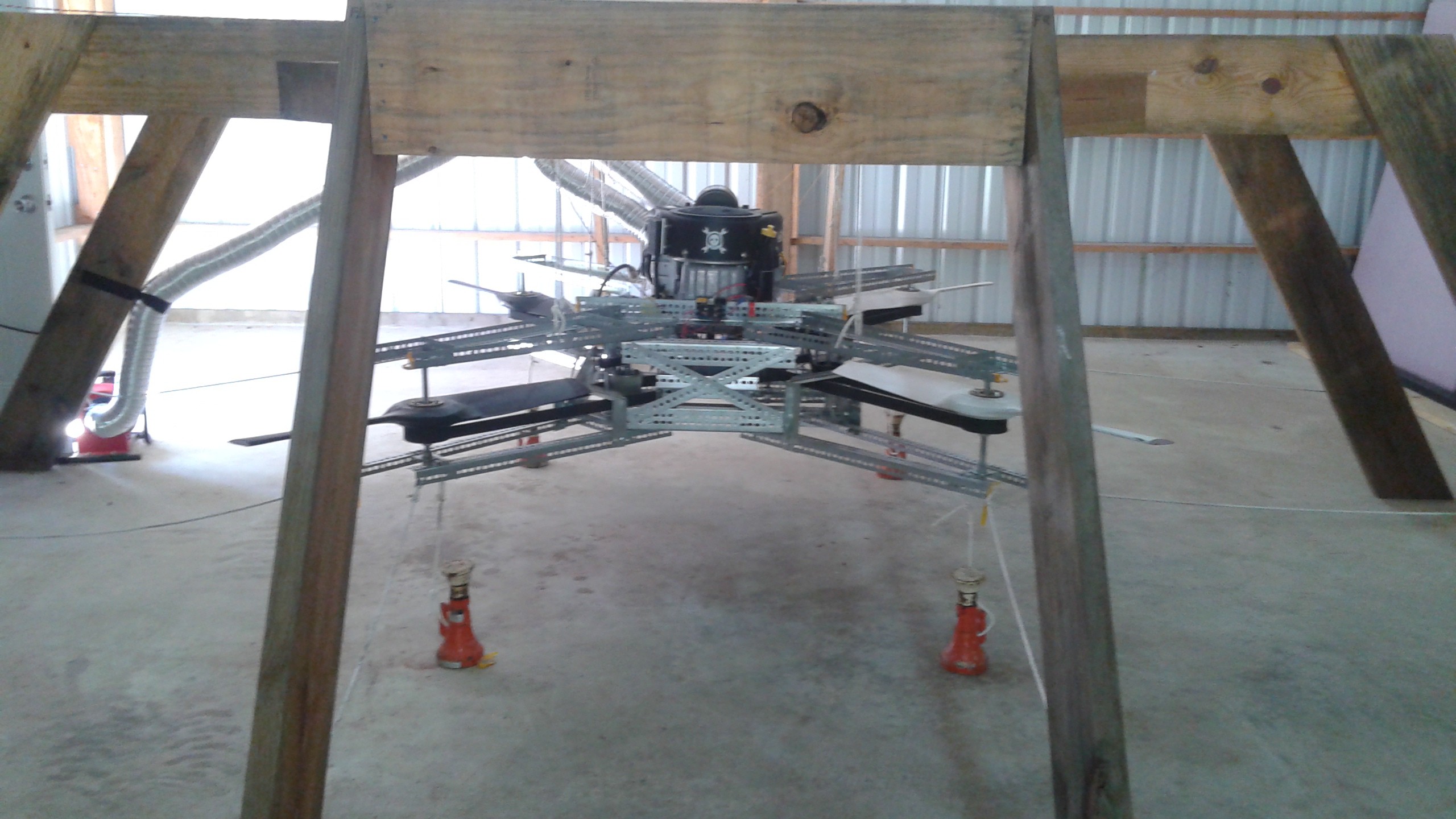
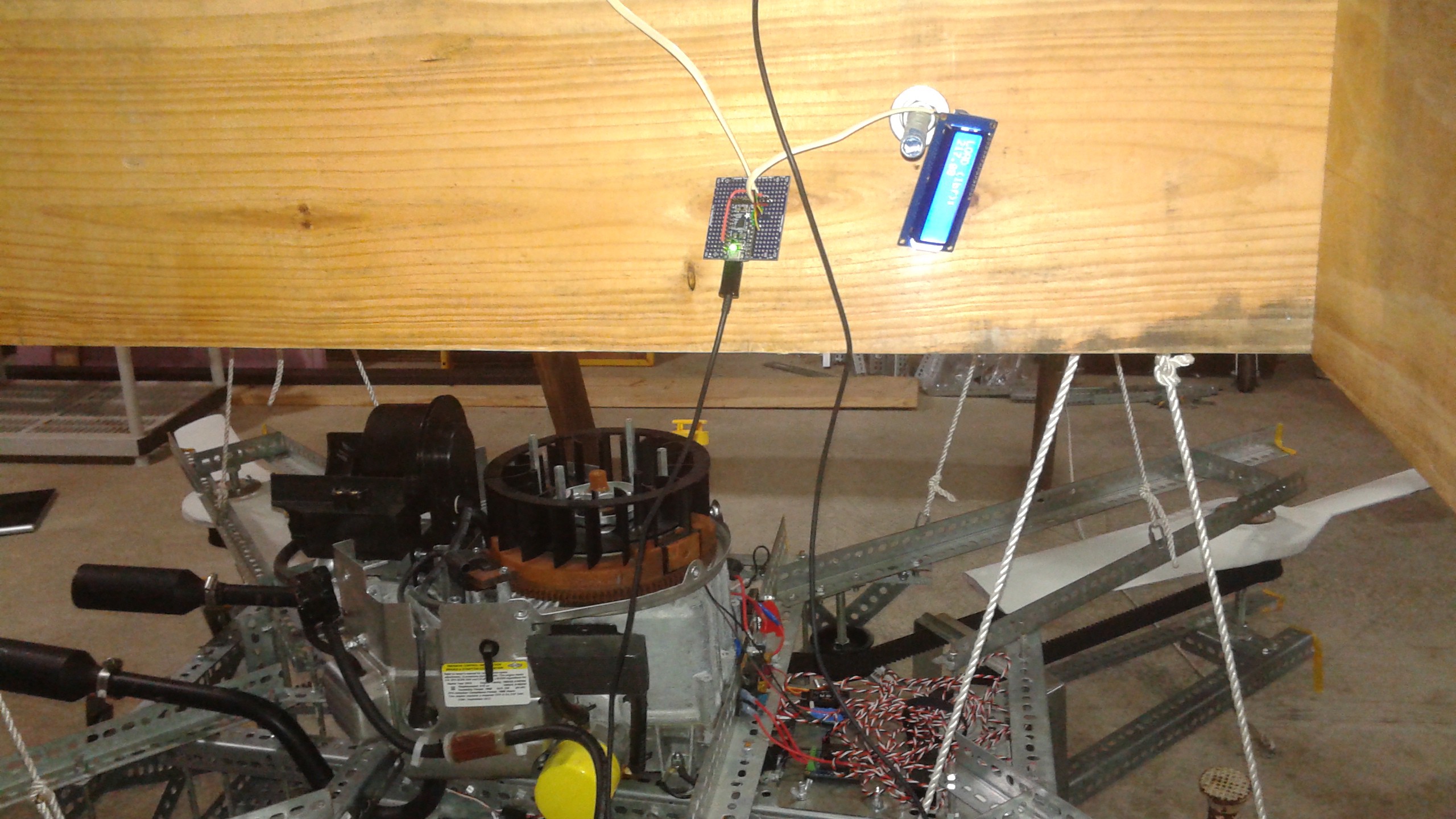
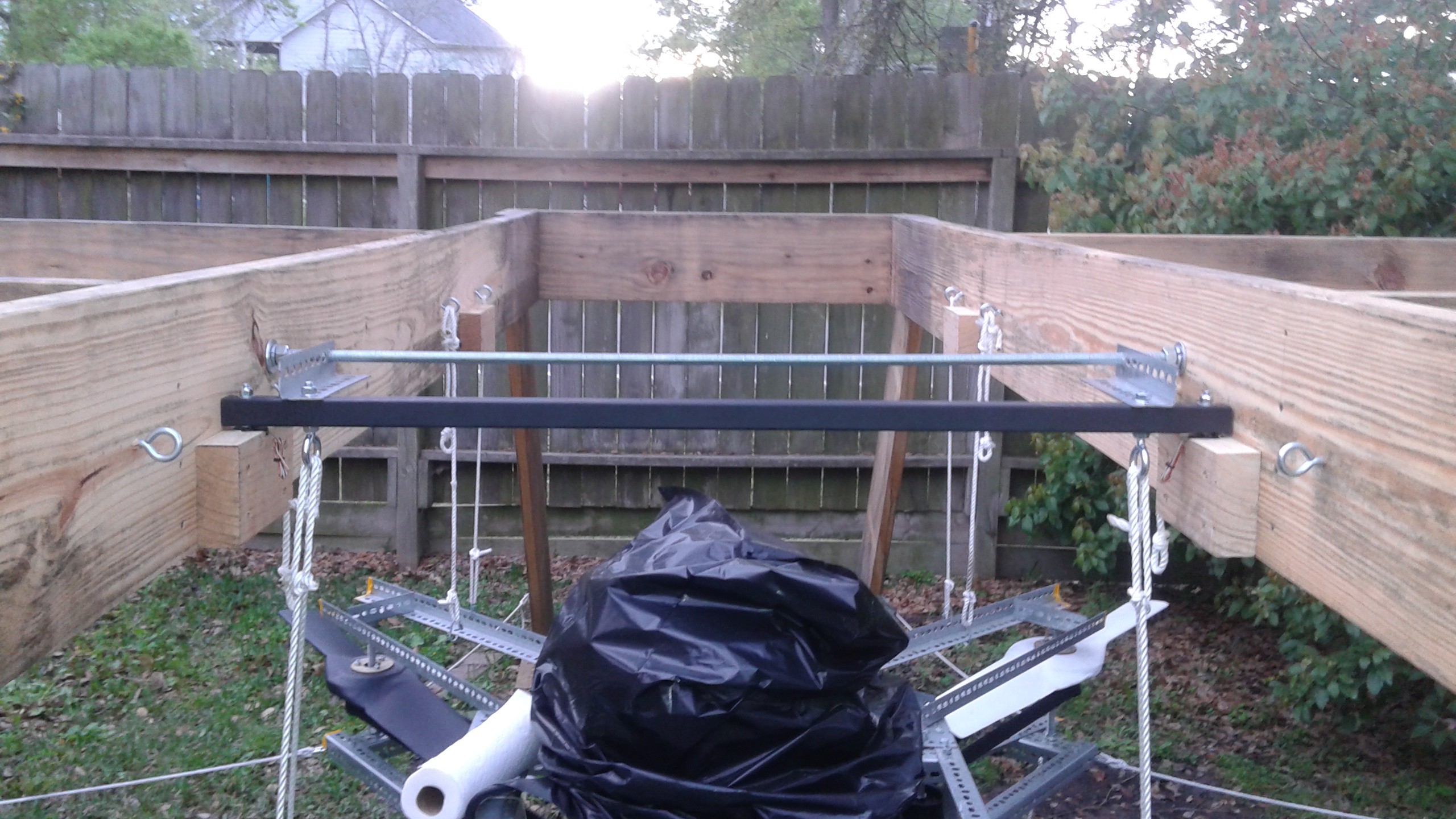
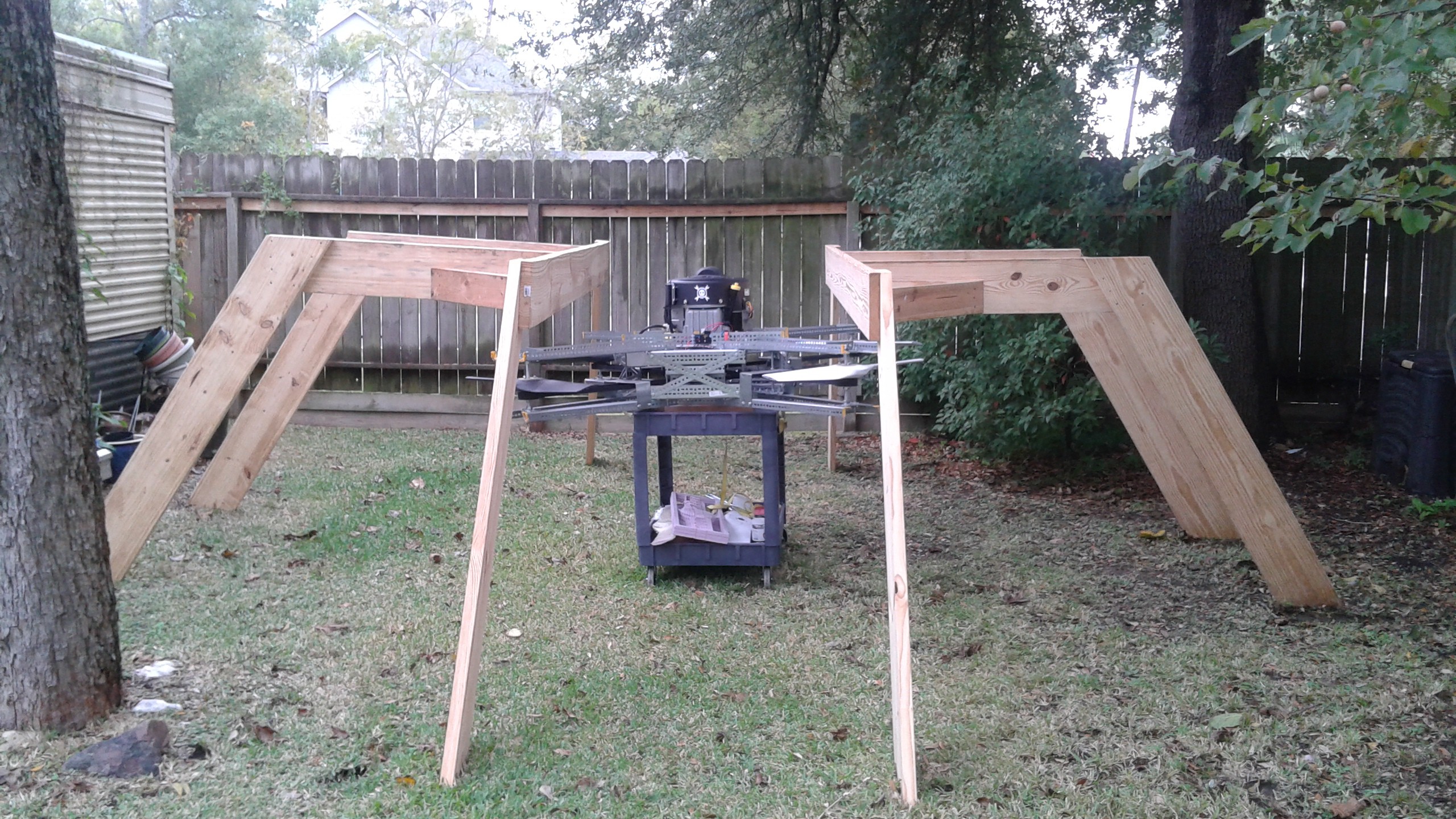
Developing a drone requires testing and data to refine the design. A useful test stand will:
- Safely support and constrain the vehicle
- Measure the static weight between tests
- Measure the thrust during a test
This Drone Test Stand is designed to try to meet those requirements.
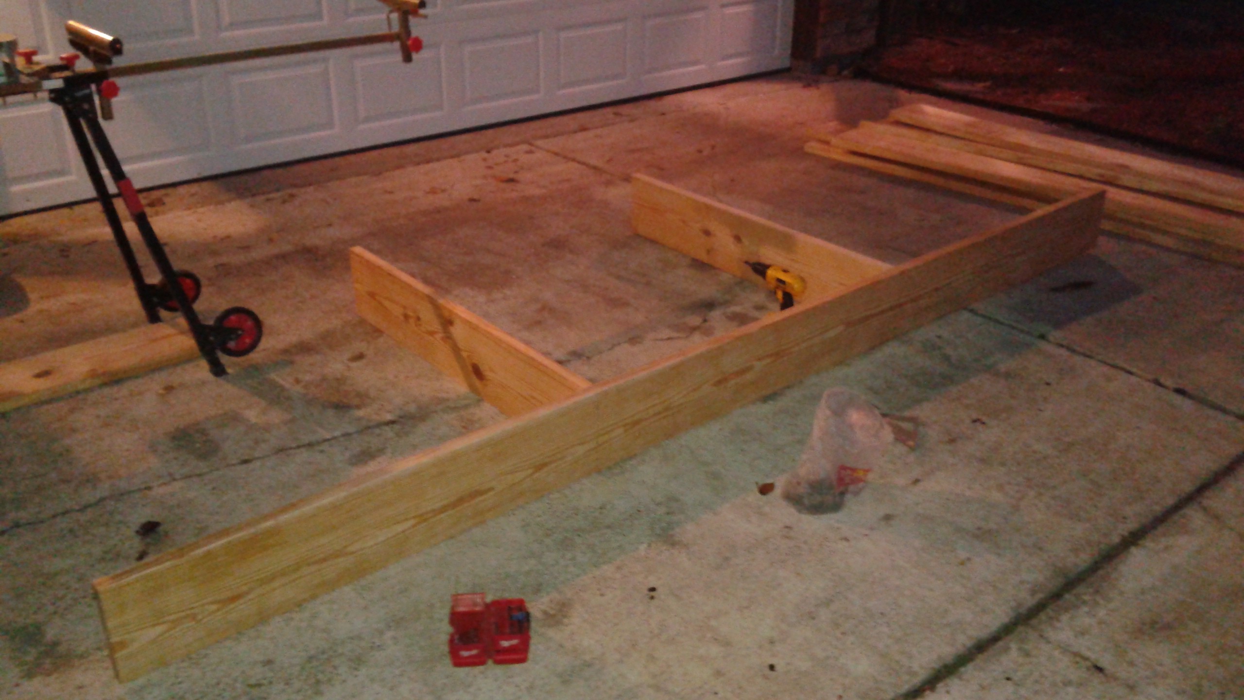
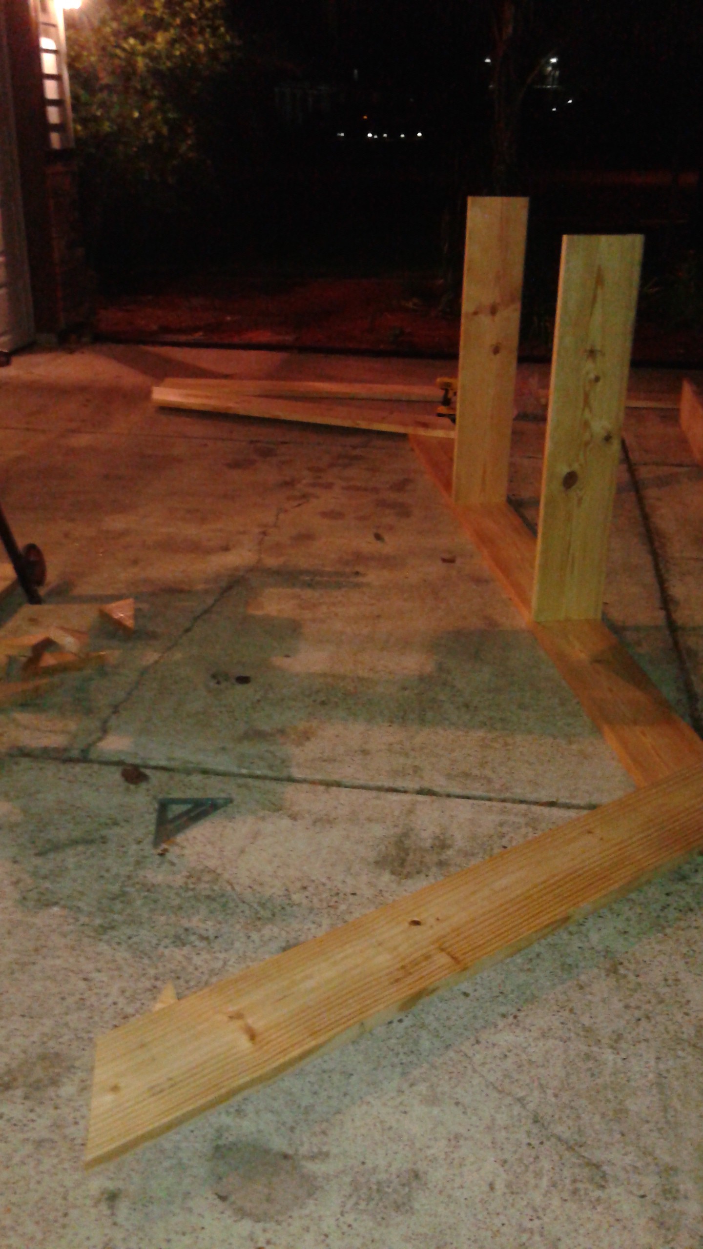
Frame
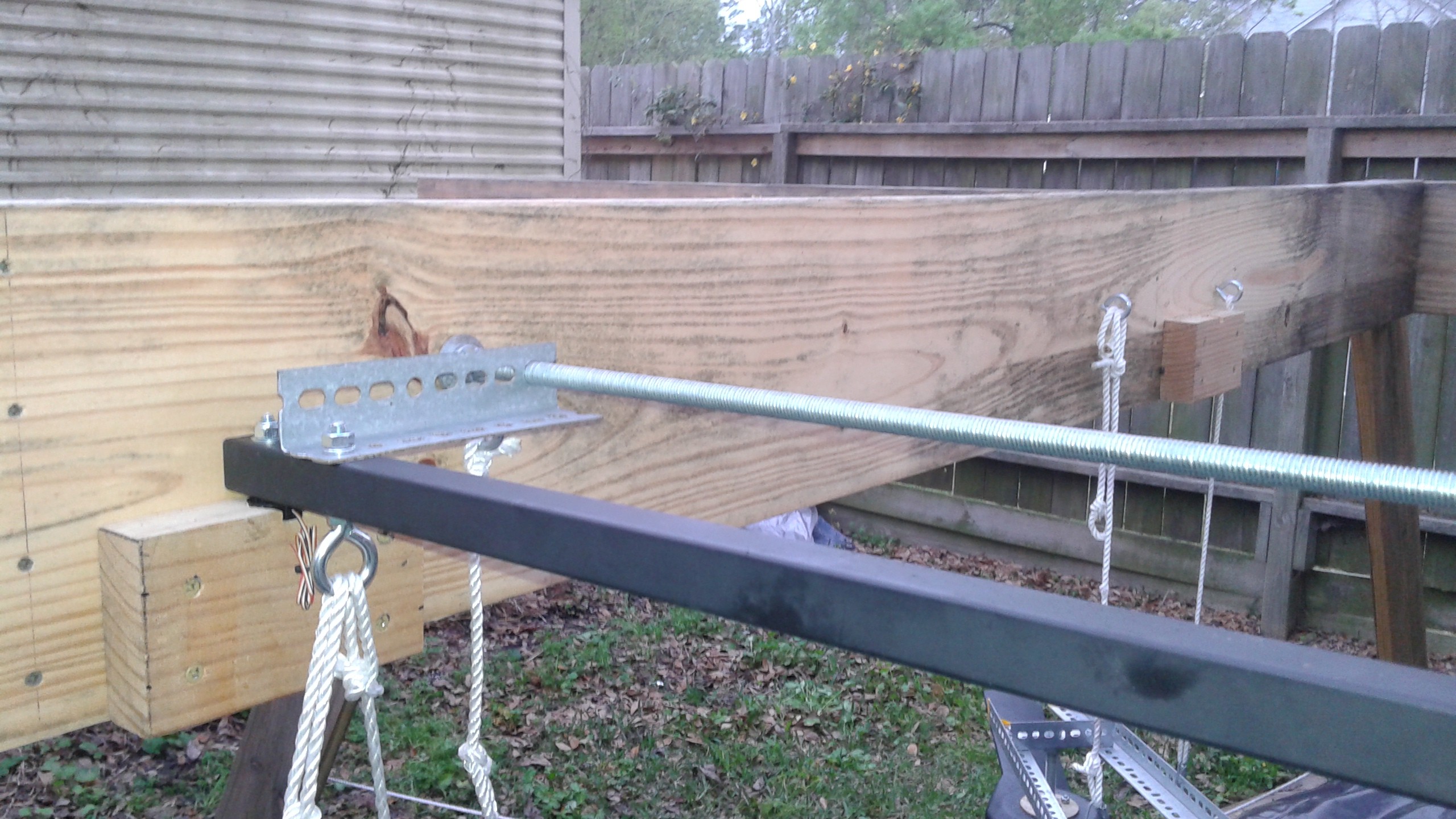
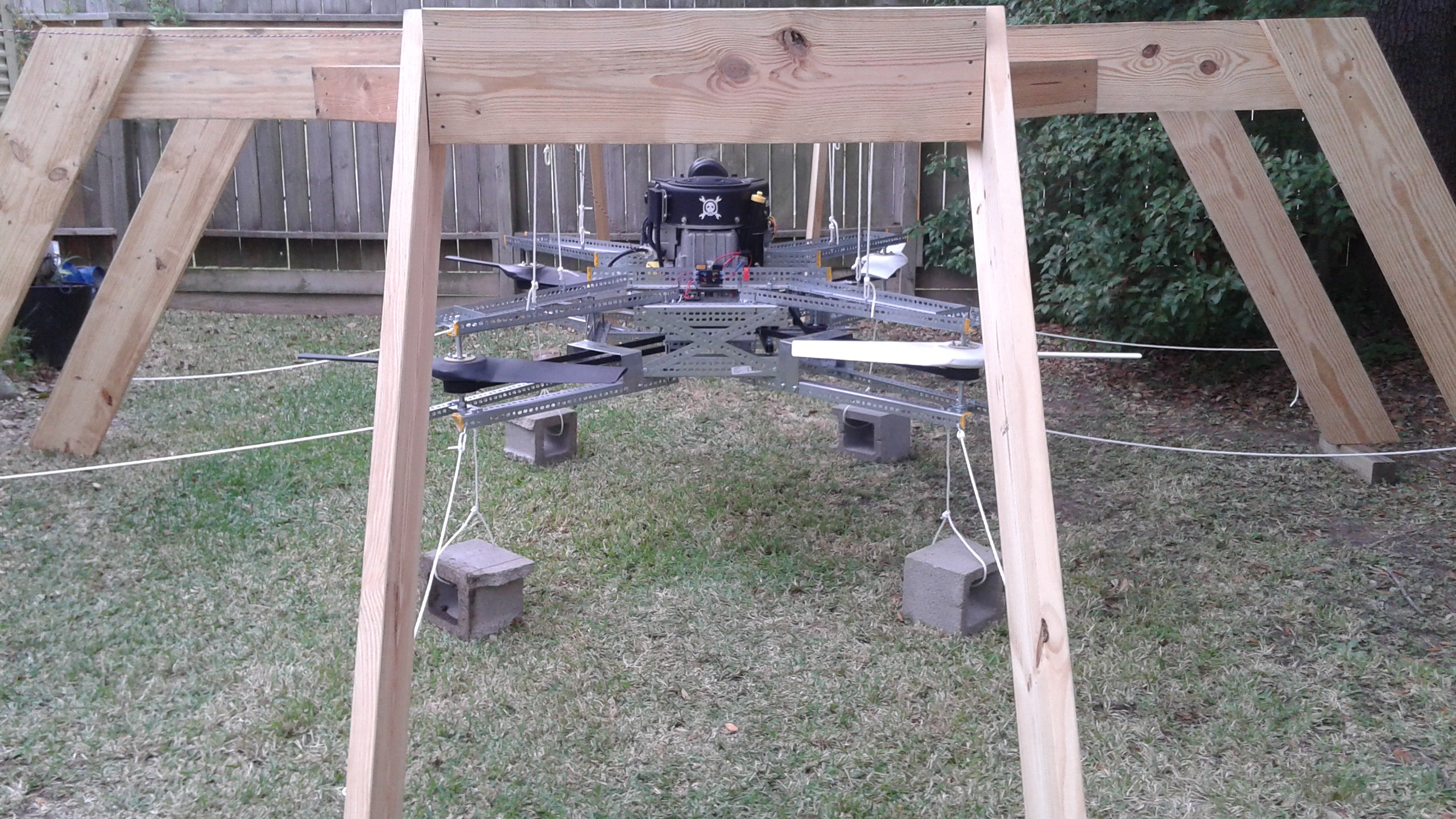
The frame is intended be in-expensive and is over engineered to ensure safety. The frame is constructed from 2" x 10" boards with joints held together with screw so that it can be disassembled easily.
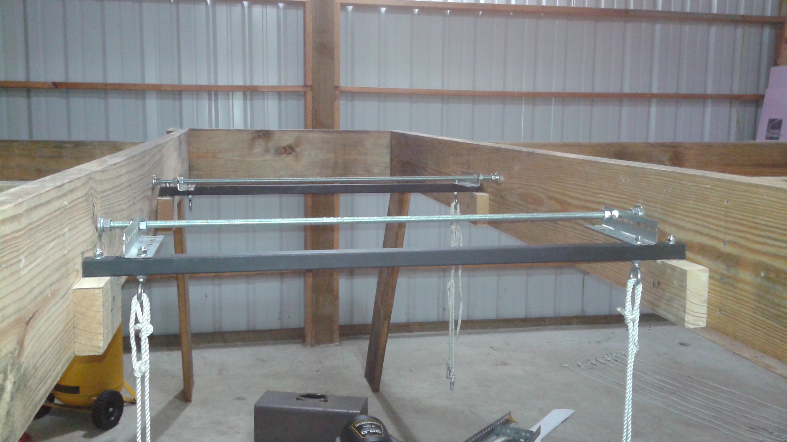
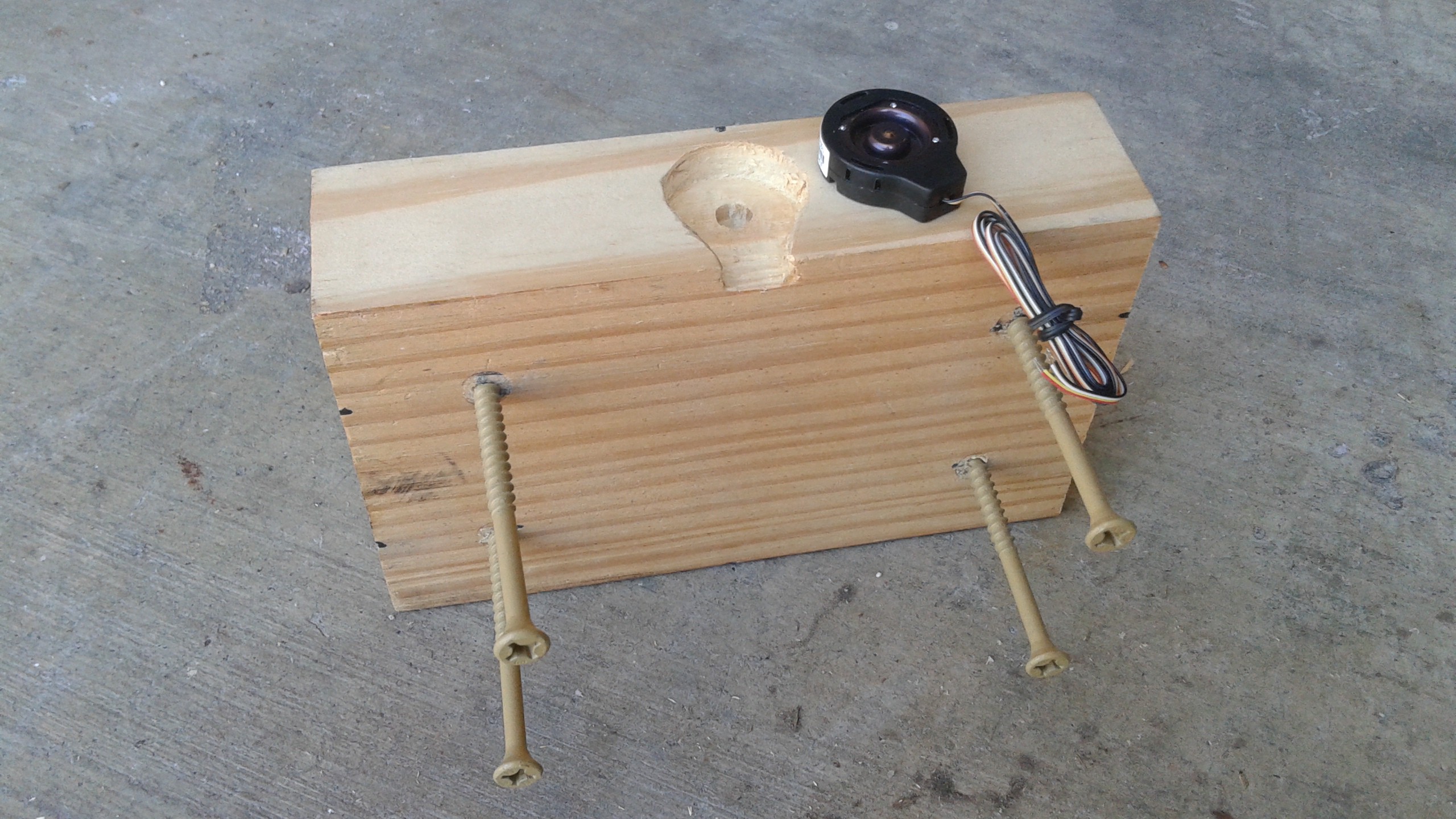
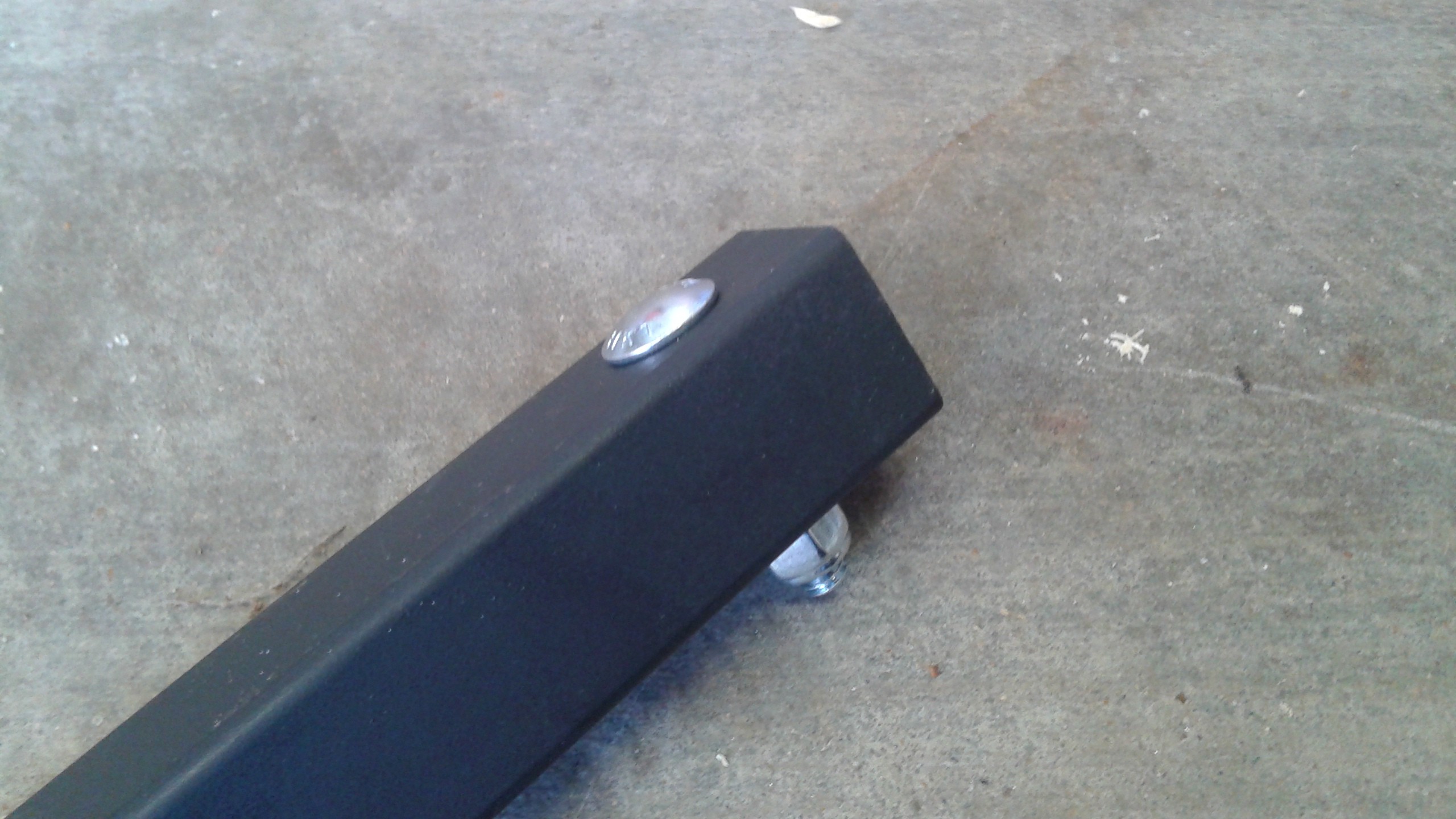
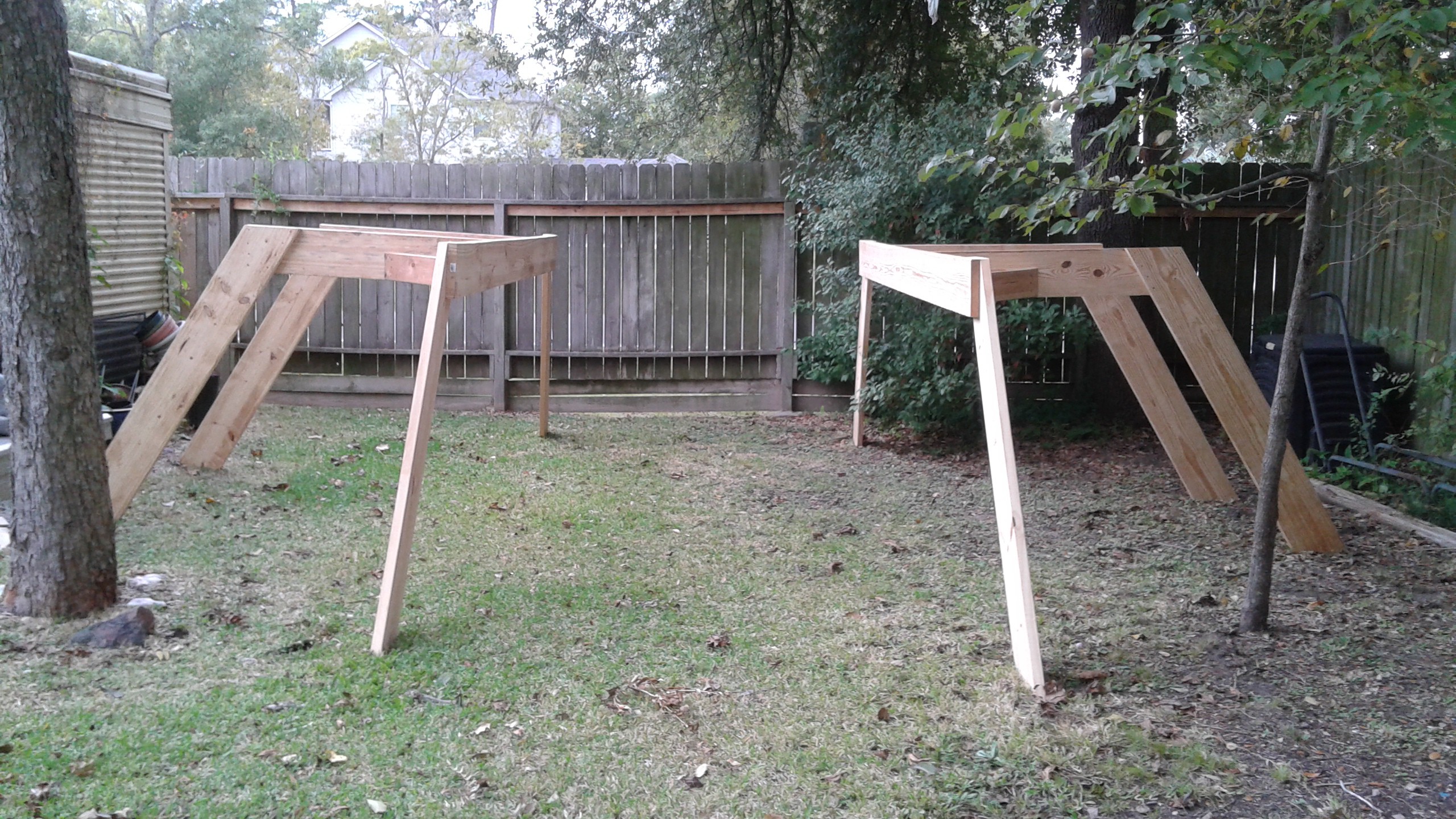
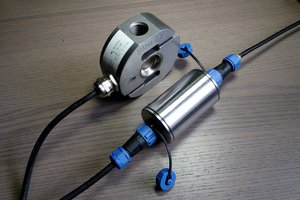
Support Bars
The support bars is where the vehicle is attached and transfers the weight of the quadcopter onto the load cells.
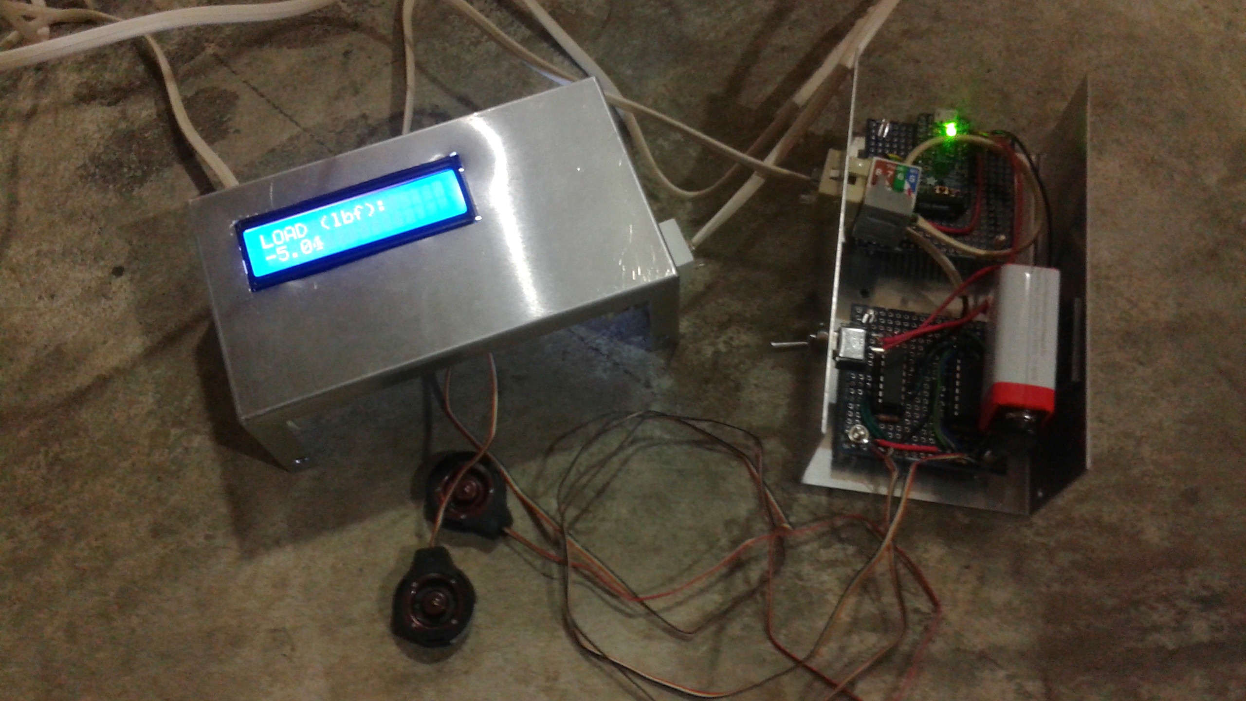
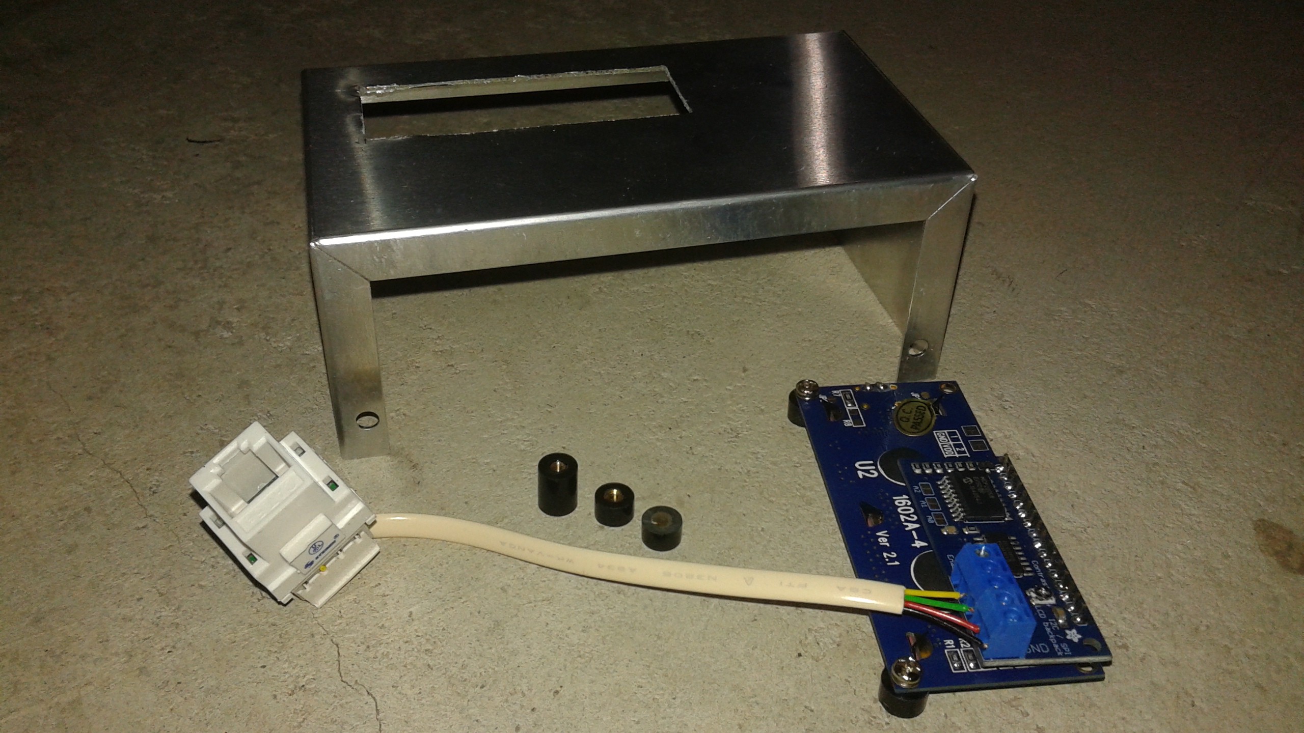
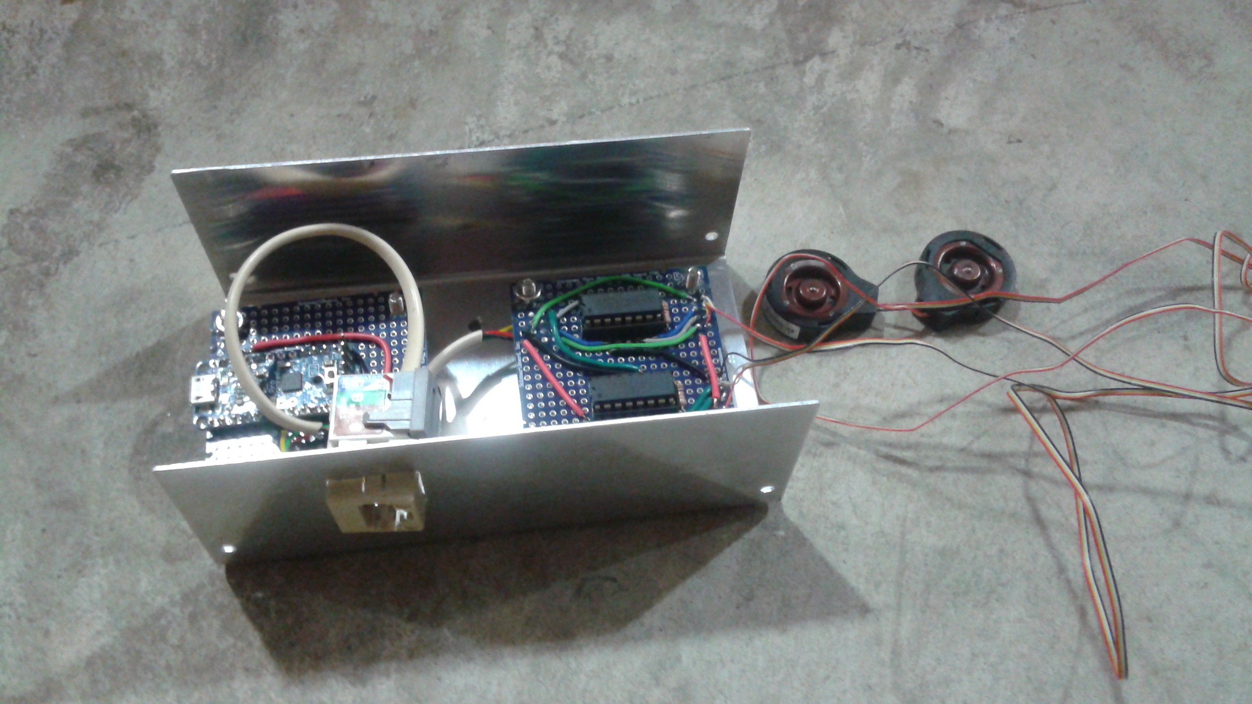
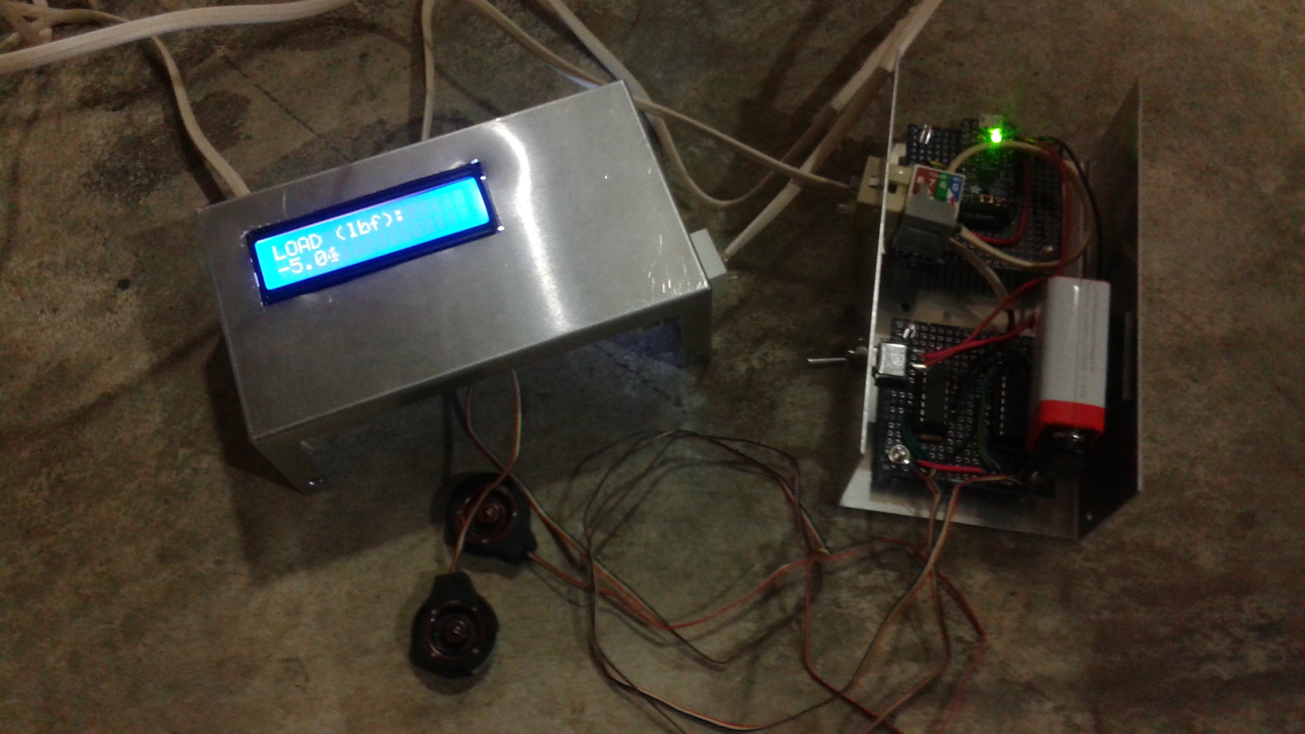
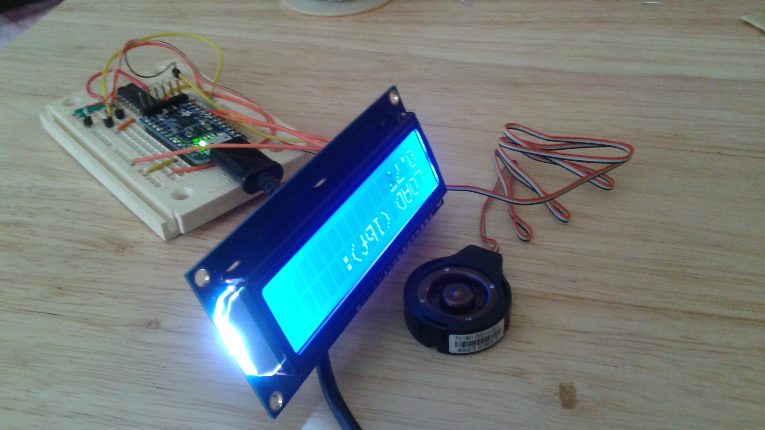
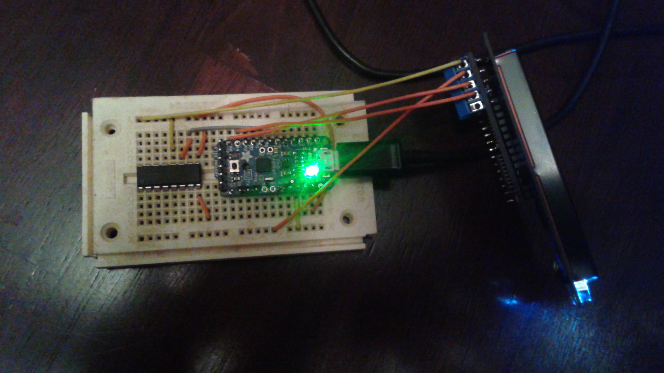
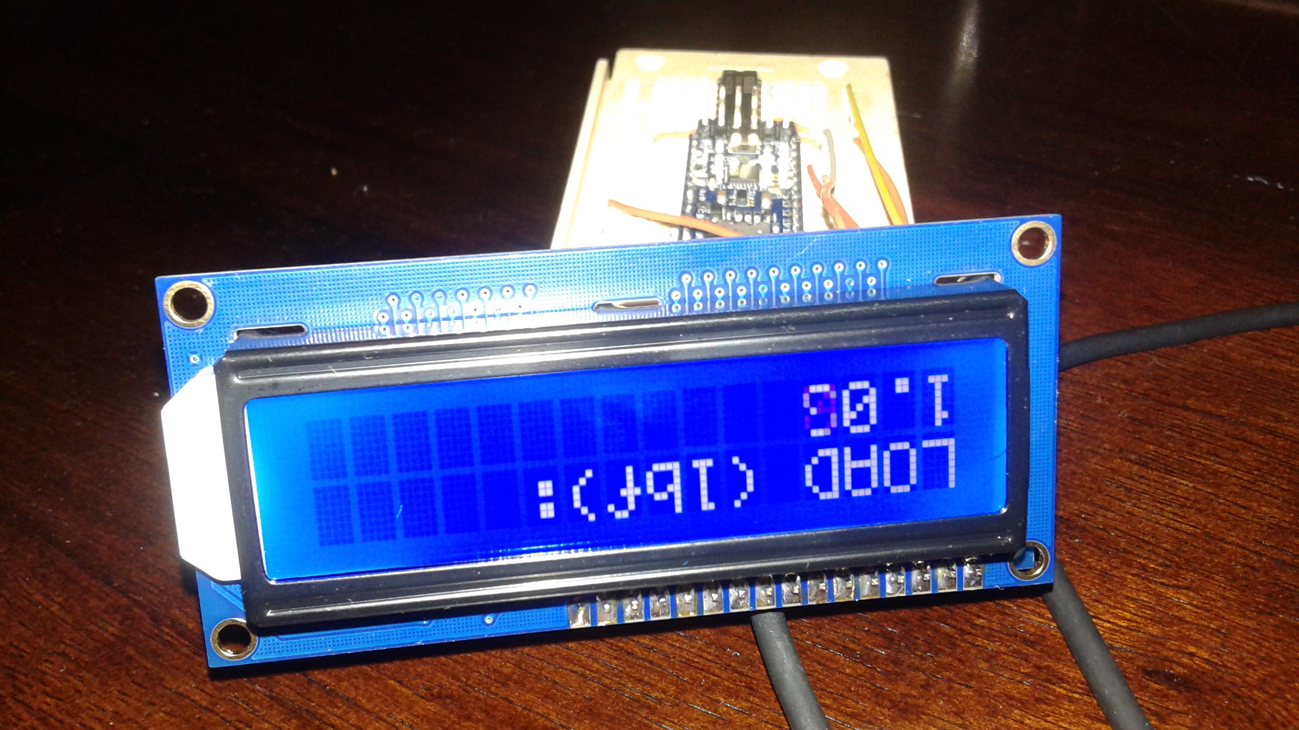
Electronics
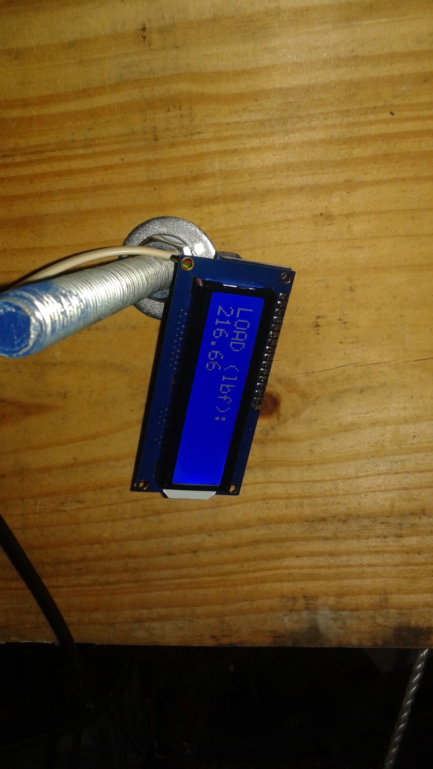
The electronics measure the static weight of the vehicle and the thrust during the test. A 5V Trinket Pro is the microprocessor at the heart of the electronics.
Code
The Trinket Pro was programmed using the Arduino IDE
/*
Test Stand Load Measurement Code
*/
// include the library code:
#include "Wire.h"
#include "LiquidCrystal.h"
// Connect via i2c, default address #0 (A0-A2 not jumpered)
LiquidCrystal lcd(0);
long time = 0;
int interval = 100;
// Load Cell
float fs_voltage = 0;
float loadcell_A = 0;
float loadcell_B = 0;
float loadcell_C = 0;
float loadcell_D = 0;
float loadcell_all = 0;
float total_load = 0;
float load_1 = 0;
float load_2 = 0;
float load_3 = 0;
float load_4 = 0;
float load_5 = 0;
float load_avg = 0;
// Calibration Data
float A_reading = 62.0;
float A_load = 0.0;
float B_reading = 1706.0;
float B_load = 233.0-4.0; //Scale -Blocks
void setup() {
long time =0;
int interval = 500; // Take a reading every 500ms
// Load Cell Calibaration
// Equation from Datasheet for reading
//float excitation_voltage = 5; // V
//float fs_output_span = 20; // mV/V
//float gain = 64; //Amplifier Gain
//fs_voltage = excitation_voltage*fs_output_span*gain;
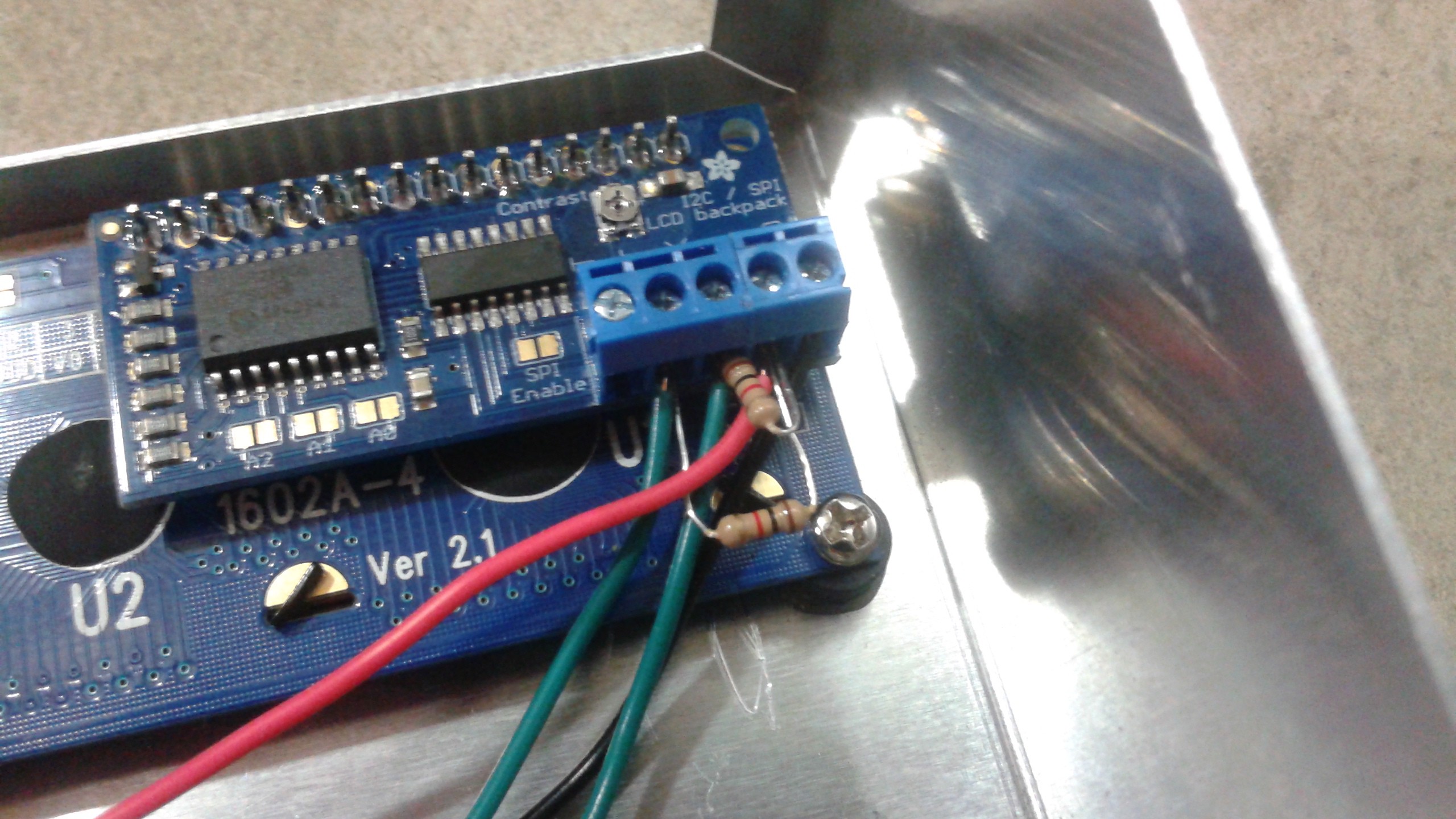
// set up the LCD's number of rows and columns:
lcd.begin(16, 2);
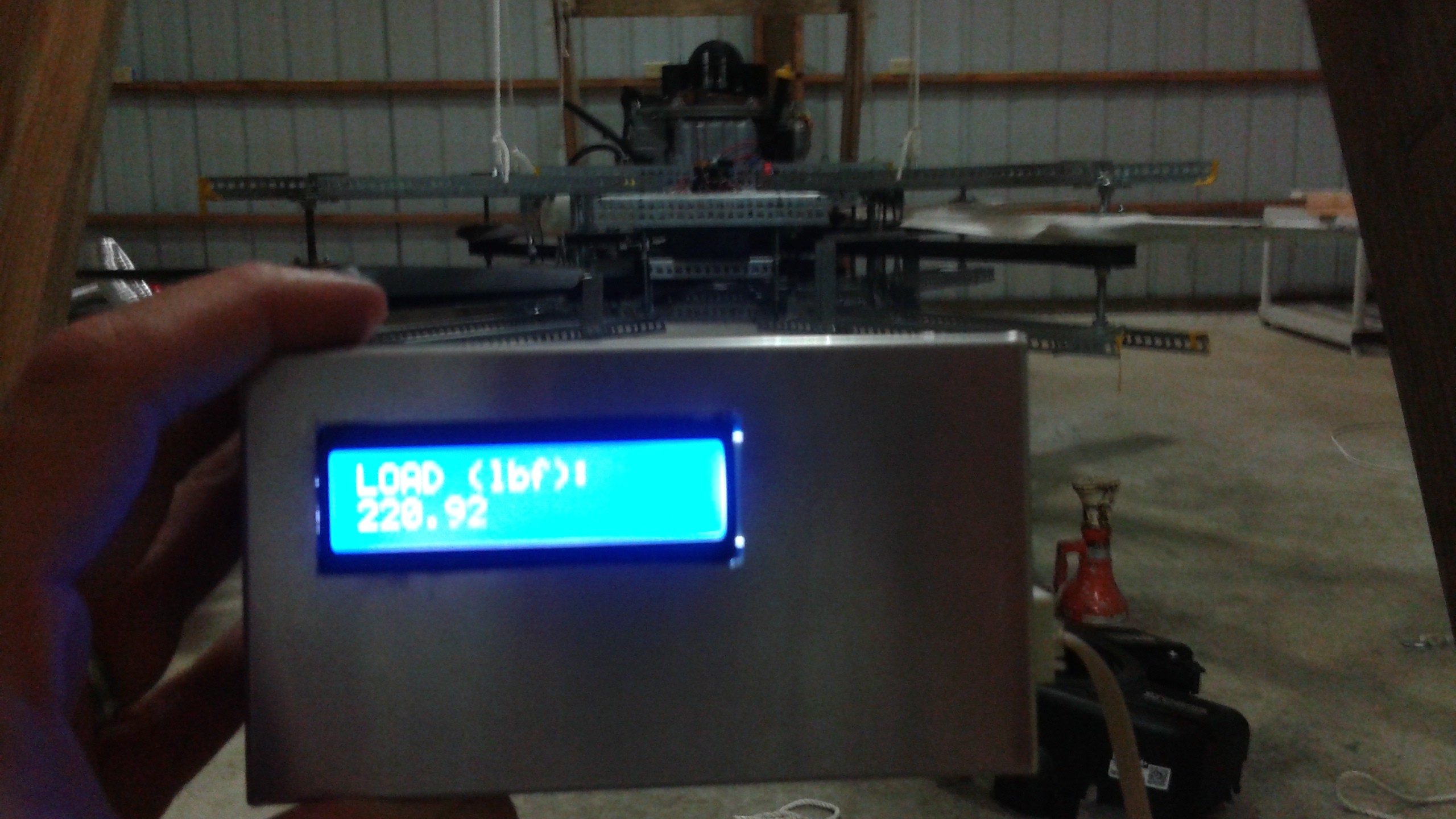
// Print a message to the LCD.
lcd.print("LOAD (lbf):");
lcd.setBacklight(HIGH);
}
void loop() {
if(millis() > time + interval) {
// Read all Load Cells
loadcell_A = analogRead(0);
loadcell_B = analogRead(1);
loadcell_C = 0;
loadcell_D = 0;
loadcell_all = loadcell_A + loadcell_B + loadcell_C + loadcell_D;
total_load = ((B_load - A_load)/(B_reading-A_reading))*(loadcell_all-A_reading) + A_load; // lbf
// Average Readings
load_5 = load_4;
load_4 = load_3;
load_3 = load_2;
load_2 = load_1;
load_1 = total_load;
load_avg = (load_1 + load_2 + load_3 + load_4 + load_5)/5;
// set the cursor to column 0, line 1
// (note: line 1 is the second row, since counting begins with 0):
lcd.setCursor(0, 1);
// print the total load:
lcd.print(load_avg);
time = millis();
}
}


 Andrey V
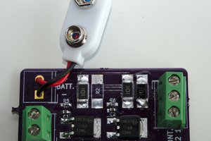
 Ben Holmes
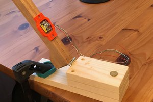
 Alexander Dvorkovyy
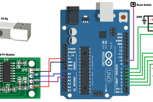
 electronicsworkshops
Hi, Just curious, how do control the prop speeds independently, with only one motor ? Cheers