 Joseph Lavoie
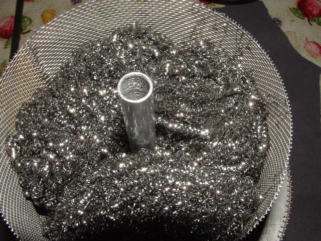
The Unit is a beta type stirling configuration and it uses a rhombic drive to move the displacer and piston with a 90 degree phase relation. The first picture is a modified exercise bike with the flywheel moved to the pedal crank shaft. The gears are starter ring gears for small gasoline engines. The second picture is the water cooled cylinder and piston. I used an old tractor cylinder and cut off the top portion. A thin stainless steel sheet wraps around the fins. Cold water enters the fins at the bottom and exits at the top through a 1/4 inch copper tube. The third picture is the heat tube . Fire will impinge directly on this tube. . The displacer is constructed using stainles steel screen and will be filled with stainless steel scrubbies purchased at my local box store.
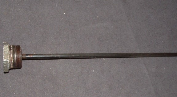
The displacer rides on a shaft that is attached to the threaded end of the main tube. This allows the displacers clearence to be very close to the main tube.
The piston:
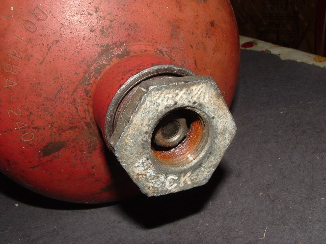
Two teflon rings are cut into the steel piston. The piston is held in perfect alignment by the welded piston bracket. The alignment of this part is very important for long lfe of the engine. You can see the gland which is a 3/4" npt flare and nut used in propane applications. I machined a teflon seal that fits into the nut .
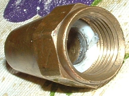
By tightening the nut the seal is 100% and the friction against the shaft is very low.
Insulator Rings;
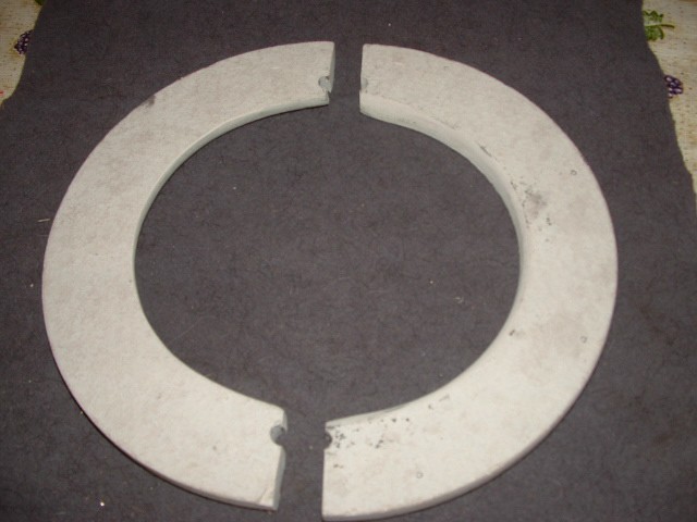
This material is a fiber board used under ceramic tiles. It machines easily but I cut it and sand it wearing a dust mask. I have used it in many projects.
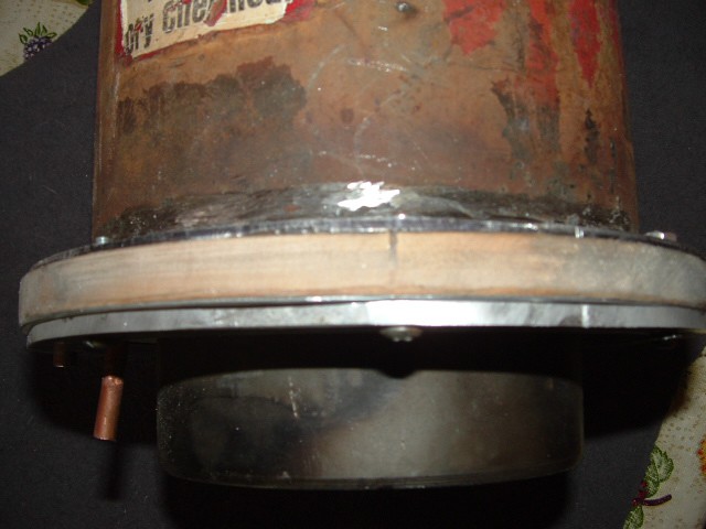
In the final assembly I will seal the unit with high heat silicone rubber. In addition to the fiber insulator a second insulator made of a hardwood pictured above is used. An aluminium ring clamps the insulator assembly together.
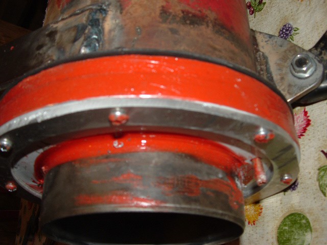
Here the cylinder has been assembled and insulated from the heat tube.
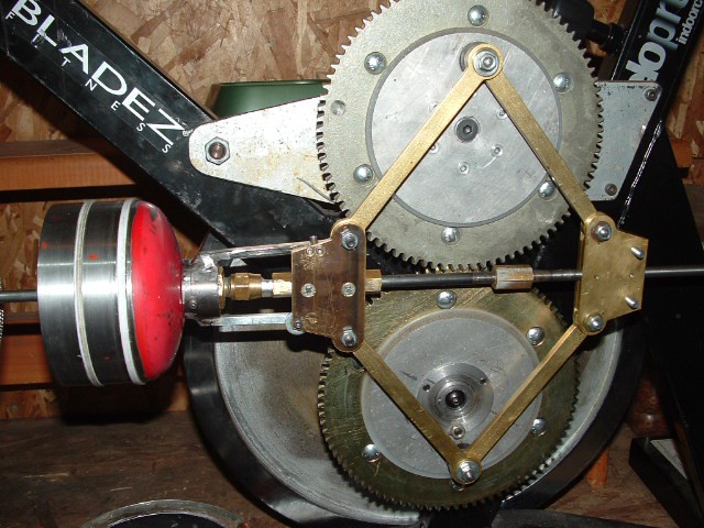
I wanted to show what is taking place inside the engine for one revolution of the flywheel. The first picture the piston is fully extended and the displacer is fully extended. The third picture the piston and displacer are fully retracted.
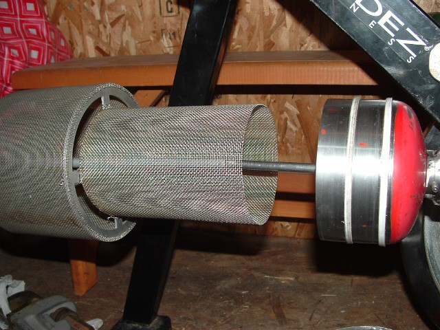
 These two pictures above show the piston a displaced position at 90 degrees. The Brass nut on the displacer shaft allows ajustment of the displacer.
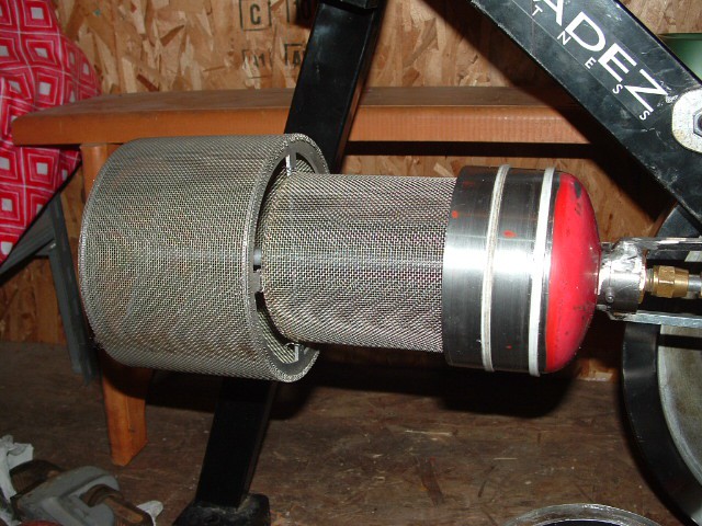
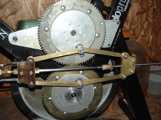
These two pictures above show the piston and displacer at 180 degrees. The displacer fits right into the piston.
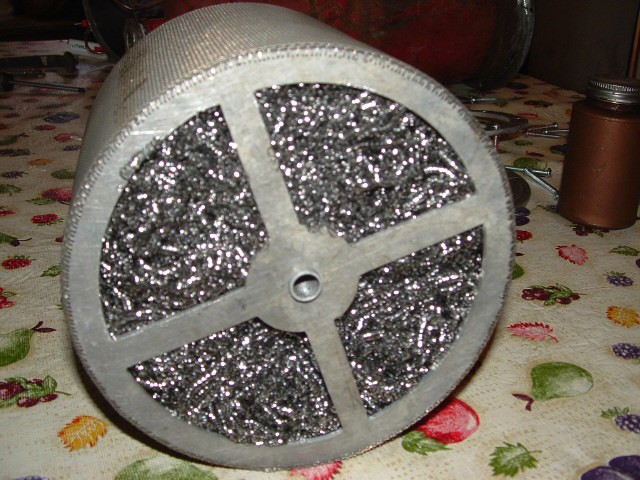
The displacer is packed with 18 stainless steel scrubies in the larger section. When the displacer is complete I will weigh it and record the data .


 M. Bindhammer
 Moritz Wenzel
 Julia Longtin
Ryan, I live On beautiful Francoise Lake, near Burns Lake. Burns Lake is our closest town.