 Elia
EliaI'll start the description with the basic specifications of the supply:
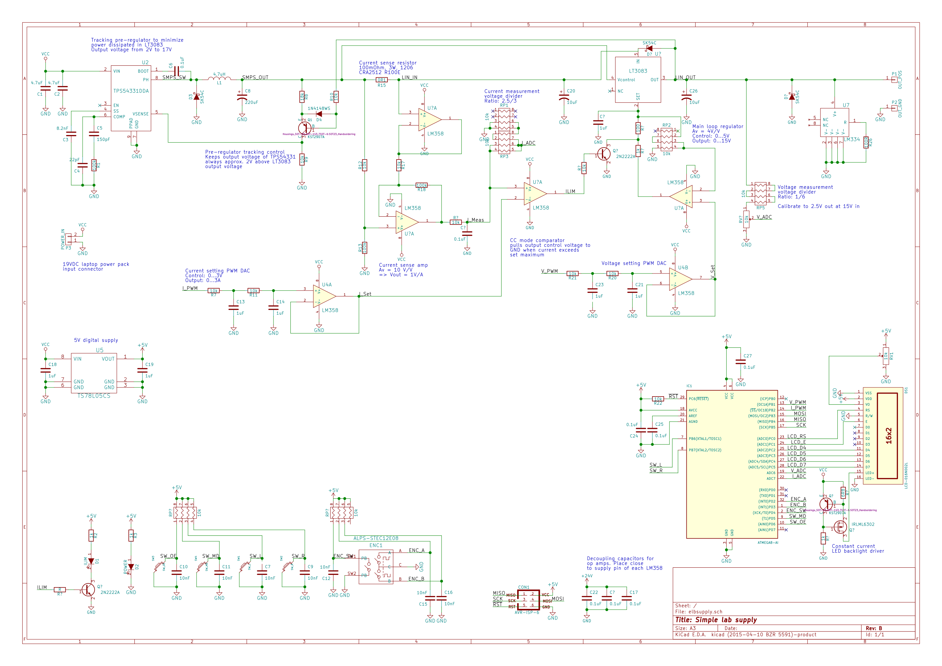
- output voltage range: 0 - 15V
- output current range: 0 - 3A
- constant voltage with current limiting and constant current modes
- mains earth isolated output so multiple supplies can be connected together for dual rail operation
- singe PCB design as a front panel for stanard extruded aluminium enclosure
The idea is to power the board from a 24V/3A laptop type power adapter so I don't have to worry about mains wiring.
The power supply is a two stage design. The first stage is a TI TPS54331 based tracking pre-regulator to minimize power dissipation in the linear regulator. This means that the supply will be able to supply the full rated current at low output voltage settings without the need for excessive cooling of the LDO.
The output voltage and current is set by the microcontroller generating two PWM signals which are filtered by a two stage RC LPF and buffered by an LM358 general purpose op amp. The voltage and current settings as well as the actual readouts will be displayed on the LCD.
The whole supply is intended to be a single PCB design which is used as the front panel for a standard extruded aluminium project enclosure. I'm not entirely sure if the aluminium case will suffice as a heatsink but I will just try it out and see if that will be okay. After all in theory the power dissipation in the linear regulator should be 9W maximum and also constant for a given output current.


 Jakob Wulfkind
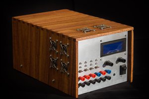
 The Big One
 CentyLab
 Paul Andrews
since github link is no longer working i found this https://github.com/CyberCircuits/elbsupply