Close
0%
0%

Audio Frequency Display

A project for Physics class.

Similar projects worth following
My Physics class requires an electromagnetism project (that is, any project relating to electricity or magnetism). In addition to the typical methods of submitting your project information, I've decided to host an ongoing project log on (in my opinion) the best place for it: Hackaday.io.

This project utilizes RC frequency filters (low/high/band pass) and LM386 op-amps to separate an audio signal into six frequency bands. These are then amplified from 1v AC to 6v AC and used to drive small strings of Christmas lights (3 lights per string). These will create a small display that glows to different frequencies of audio.

Note: there is a MUCH easier way to complete this project. You can simply use a microcontroller, an input circuit to interface AC voltage with an ADC, and relays to drive any AC circuit. However, that would be quite easy to wire up and wouldn't teach me personally anything huge about electronics (it would mostly utilize concepts I already know).

This project aims to help me understand RC frequency filters and the basics of op-amps (and their derivative, LM386 amplifiers). The circuitry forms two main "stages" in which the audio is processed to make a Christmas light display.

Though this is a school project and is being documented in-house, I'm also documenting it here as a means to show the details that hackers and makers might find interesting (while instructors might be more concerned in the physics behind the project). I'm also hoping I might get some feedback to catch mistakes before they happen (though they make for good writeups and learning experiences all the same).


Stage 1: Filtering

This uses the aforementioned RC filters to strip the audio signal into 6 frequencies:

  • 0-32 Hz
  • 32-256
  • 256-512 Hz
  • 512-2048 Hz
  • 2048-8192 Hz
  • >8192 Hz.


Band-pass filters are formed by combining low and high pass filters. Without taking load resistance into account, the equation for a filter's blocking frequency is

\color{White} \large \color{White} \large $F_\text{filter} = \frac{1}{2 \pi RC}.$However, LM386 amplifiers have a 50 kΩ resistance, so this must be taken into account when calculating resistor values. I'm using 100 nF capacitors for all the filters as that's what I have on hand (I've got a resistor kit for getting odd resistor values).


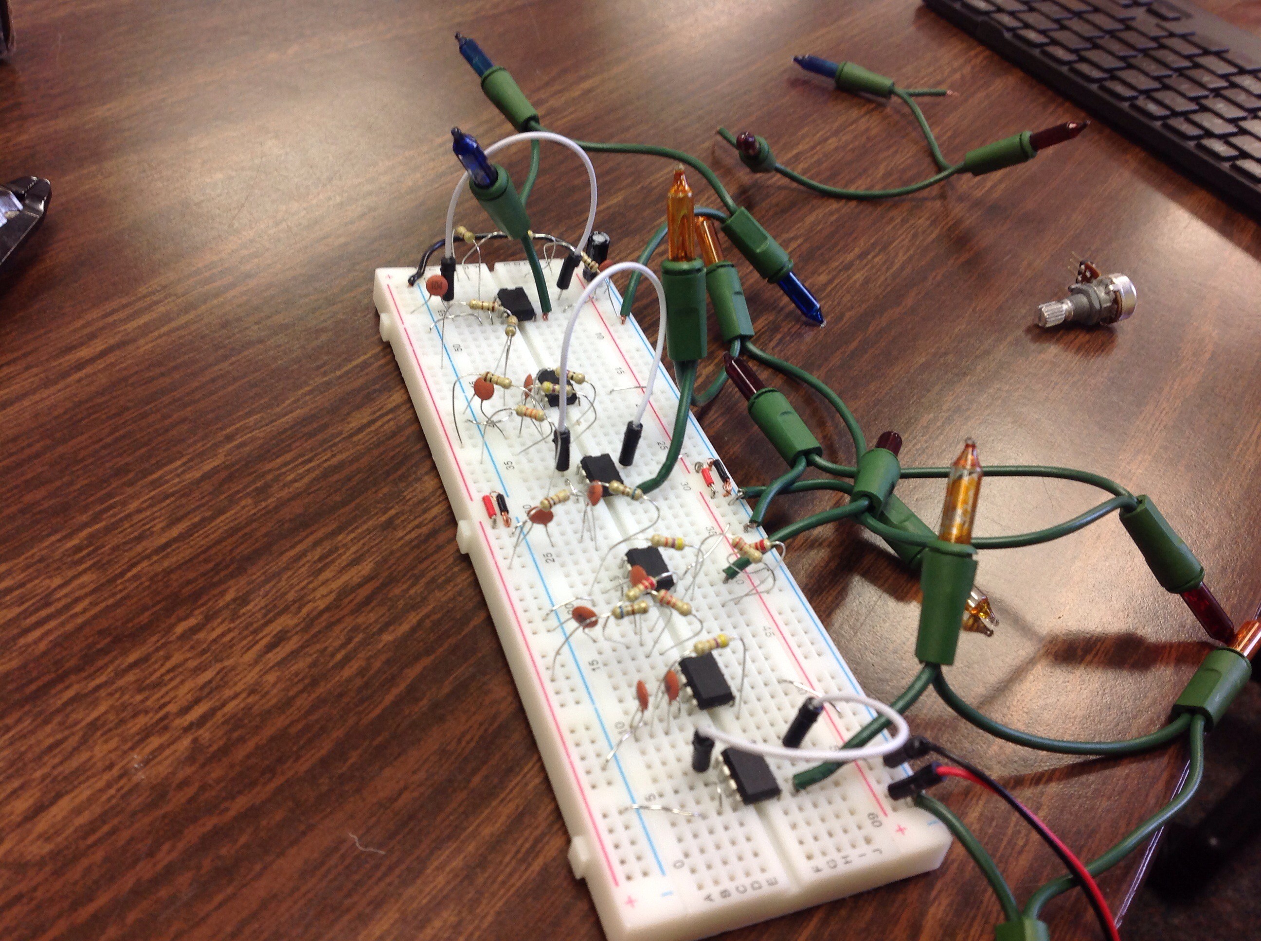
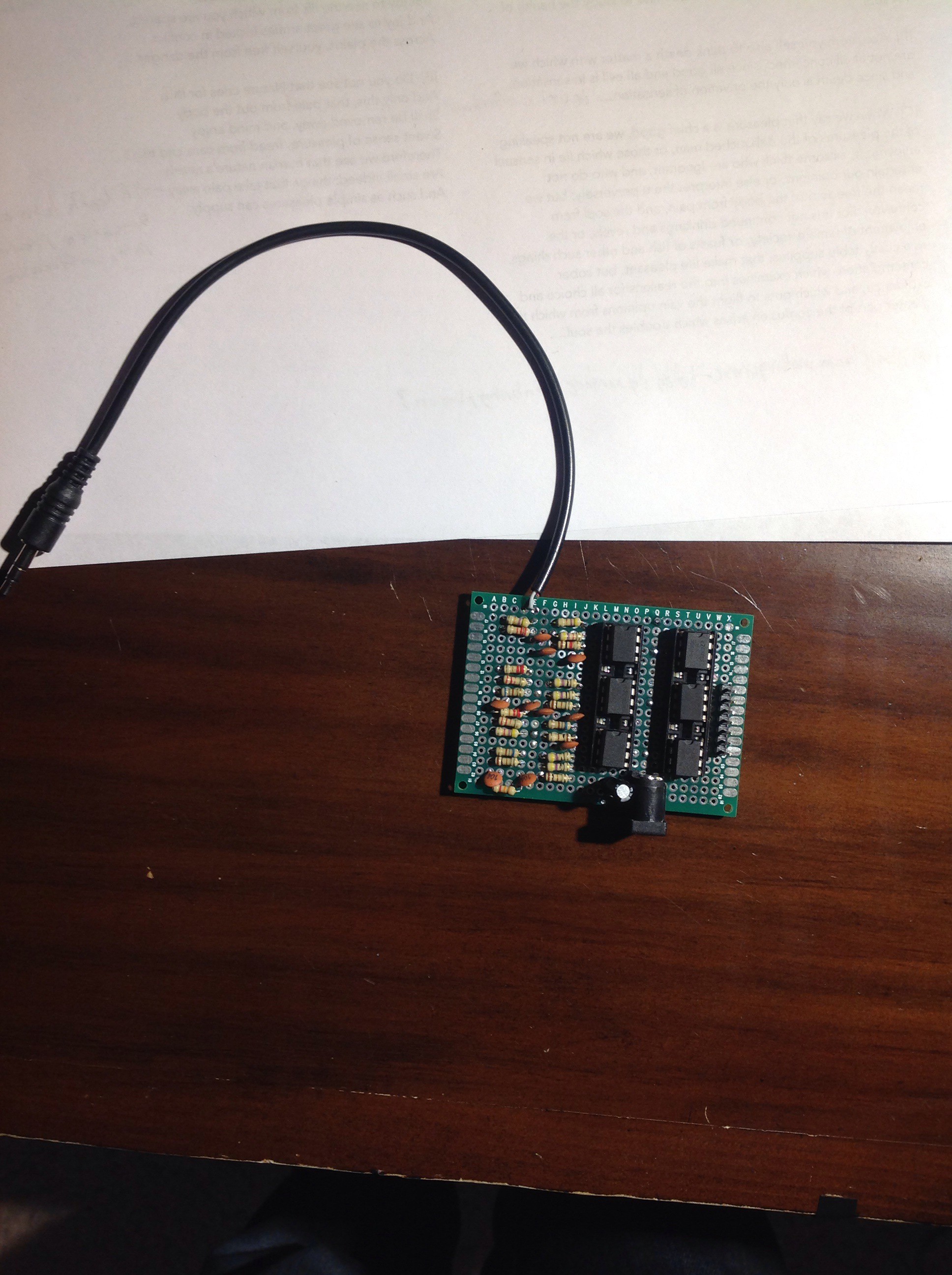
Stage 2: Amplification

This is nothing fancy, just a LM386 with the default 20 gain, a small RC filter on the end (taken from the TI datasheet-I'm still trying to figure out what that does), and a DC blocking capacitor. Multiply that by six frequency bands, and you get a lot of repetitive soldering. I'm going to power them off of a 12v DC input, so I should get a 6v AC output to drive the Christmas lights (which are around 2v AC each). If there's a small voltage drop, nothing bad happens-the lights just get dimmer. It's too bad I had to order these off Amazon-they come in 5 packs and I needed 6. Oh well, at least I have extras in case one blows up.

  • 40 × Various resistors and capacitors Too many different values to count
  • 1 × Audio input cable 1 standard cable cut in half makes two cables with a solderable end!
  • 6 × LM386 Audio ICs / Audio Amplifiers
  • 18 × Christmas lights Nope, no LEDs here!

  • Rendering...rendering...still rendering...

    CompuCat03/09/2015 at 02:47 0 comments

    Phew, I've just finished a ton of work on this project.

    First-my board had errors. There was an output jumper connected to the bypass pin of one of the LM386s instead of the output-d'oh! Also, the input cable broke. I threaded it through a mounting hole for some more strain relief this time.

    Next-cutting materials. I cut a piece of particle board and a frosted acrylic panel to mount the project on. The lights were hot glued to the particle board, and I'll use some nylon screws, spacers, and nuts to mount the acrylic away from the board so it can diffuse the light from the Christmas lights. After gluing this, I had to solder the huge wire harness up to a connector to attach to my driver board. Quite annoying-the long loopy wires tend to flap all over the place. It also took up a ton of red hookup wire-I'll have to get some more soon.

    I also have had to shoot a presentation video over the past few days for my school. (Due to privacy concerns, I won't be posting it here.) It's "only" 15 minutes (my school wants a 5 minute video). Oh well. Also, my video editor (being a bit on the older side) runs kind of slow, enjoys crashing, and takes forever to render. The final video (MP4, 1080p) only renders 2-3 frames per second, making for a close to 3 hour render time. Ouch. I'll probably have to render this overnight, which adds another problem: my computer has a quite inefficient CPU cooler and is thus quite noisy. Hopefully I can get some sleep tonight.

  • Wishing I knew how to etch PCBs.

    CompuCat03/04/2015 at 04:49 0 comments

    As you can probably guess from the title, I just had to do a humongous soldering job. First, let's back up a bit earlier in our story.

    I made a couple changes to the circuit, including shorting the gain pins of the LM386s to boost the signal gain and removing the small RC and DC blocking capacitors on the output of the amplifiers. After implementing the circuit on a breadboard, I tested and began to dissassemble it for soldering. I only remembered to take the photo right after I began pulling apart the breadboard version, but most of the parts are still on there.

    Quite a mess, huh? It gets worse. I had to take these parts and then transfer them onto a 5x7cm piece of perfboard. There were quite a few more jumpers than I would have liked, but I don't know how to etch PCBs yet (which would have been quite handy) and I didn't have the time (The project is due next Wednesday, March 11, 2015). Here's a couple of photos (with various objects for scale). Next up: building the actual display board and mounting the lights.

    People really need to stop using quarters as size references! All these other coins are feeling quite left out.

  • A slight snag

    CompuCat02/25/2015 at 23:50 0 comments

    I just noticed while prototyping that using a DC wall-wart causes audio artifacts if I amplify the sound too loudly. I'm assuming this is due to noise (batteries are quite clean power sources)-I thought I had a decoupling capacitor on my voltage rail for a 7805 circuit the wall wart is also powering, but it turns out that the capacitor is on the output side of the regulator, not the input. D'oh!

  • LM386 arrival, test

    CompuCat02/25/2015 at 00:40 0 comments

    Alright, we've finally got all the parts here (I think). The LM386s I had to order from Amazon have finally arrived. Then again, I did choose free 2-day Prime shipping, so it wasn't that long of a wait. I haven't had much time to do much with them, but I decided to use a leftover 8 ohm speaker I pulled out of somewhere to breadboard a test amplifier.

    Yes, a can. Nope, not pop. And yes, I'm still using an iPhone 3GS. It works!

    There's not much to it-just a hacked-up audio cable, the 9v battery, an LM386, 2 capacitors, a resistor, and the speaker. It's almost identical to the TI reference schematic, but with a 10 uF capacitor replacing the 250 uF DC blocking capacitor, the 0.05 uF capacitor replaced with a 0.1 uF capacitor, and no input potentiometer. Surprisingly, it sounds much better when the speaker is placed upside-down on top of a hollow spool of wire (or two). I found the best setup, however, was using an empty soda can-I think the air chamber it forms just allows the sound to resonate a bit better. It's a bit sensitive to me jiggling the input wires, but otherwise, it's quite a neat little amp. Good enough for me!

View all 4 project logs

Enjoy this project?

Share

Discussions

Similar Projects

Does this project spark your interest?

Become a member to follow this project and never miss any updates