 Jac Goudsmit
Introduction
I've owned a MicroKim by BrielComputers for years, but it had been defective for a long time: as it turned out, the EPROM was malfunctioning. This project describes how I found out what the problem was, and how I fixed it. And hopefully it gives you some ideas on how you could use a Propeller to enhance your own (1MHz) 6502 computer.
As you may know, I've been working on two projects for a while, which I like to call "software defined computers", called Propedle and L-Star. The idea behind those projects is that a Parallax Propeller is fast enough to connect it to a 1MHz 6502 (or 65C02) and be in control of what the world looks like in the eyes of that CPU. The Propeller is connected to the address bus and data bus and makes the 6502 think that there are more devices in the system than there really are. The difference between this KimStar project and the other ones is that in this case, we start out with an already fully functional 6502-based computer and let the Propeller "get on the bus" (literally), whereas the Propeddle and L-Star are more of a "blank slate" and won't work at all without the Propeller.
KimStar is really just a Propeller on the address bus and data bus of an existing 6502 computer, and has no need for other chips such as memory chips or glue logic, unlike Propeddle and L-Star. After I used KimStar to fix my MicroKim, I imagined it could be used as a proof of concept for those who own a MicroKim and want to try expanding it in their own way with hardware that can they can buy cheaply. I used a Propeller QuickStart board and some wires to build this. If there is enough interest, I might consider designing a PCB and making it available as a kit.
Be sure to click the "Read More" link below for lots more information!
Setup
The QuickStart is a simple board with an almost minimal Propeller circuit. Besides the P8X32A (the official designation of the Propeller), it also has an EEPROM to store the firmware, a replaceable crystal and an FTDI USB-to-serial controller. There are also a few LEDs and touch sensors, but most importantly there's an expansion connector that gives access to all of the 32 digital I/O pins.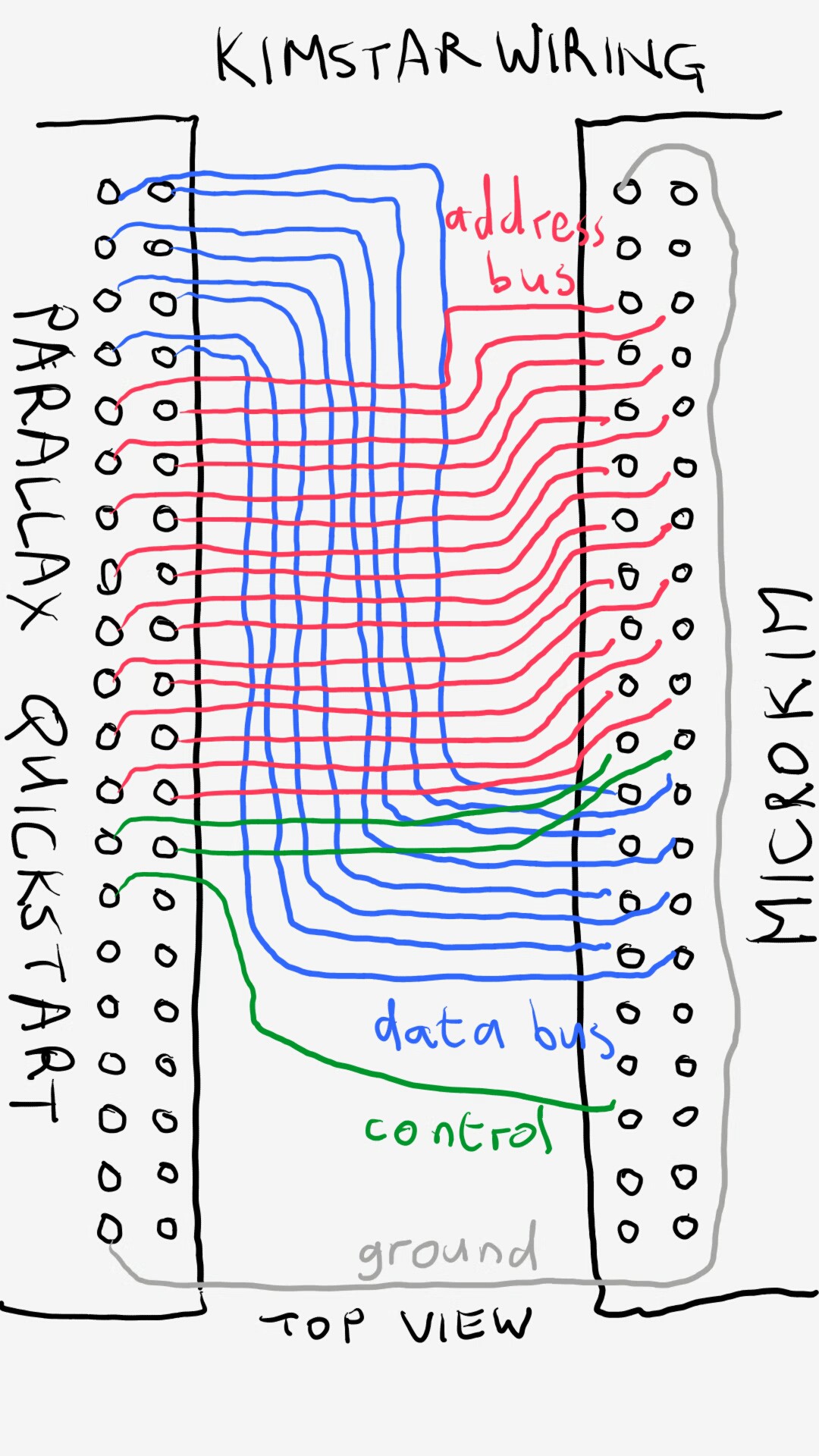
I connected wires between the QuickStart and the MicroKim as shown above, and as listed in the table below:
| QuickStart pin | Propeller pin description | MicroKim pin (standard numbering) | MicroKim pin (numbering as in BrielComputers schematic) | MicroKim pin Description |
| 1 | P0 | 23 | 12 | D0 |
| 2 | P1 | 24 | 29 | D1 |
| 3 | P2 | 25 | 13 | D2 |
| 4 | P3 | 26 | 28 | D3 |
| 5 | P4 | 27 | 14 | D4 |
| 6 | P5 | 28 | 27 | D5 |
| 7 | P6 | 29 | 15 | D6 |
| 8 | P7 | 30 | 26 | D7 |
| 9 | P8 | 5 | 3 | A0 |
| 10 | P9 | 6 | 38 | A1 |
| 11 | P10 | 7 | 4 | A2 |
| 12 | P11 | 8 | 37 | A3 |
| 13 | P12 | 9 | 5 | A4 |
| 14 | P13 | 10 | 36 | A5 |
| 15 | P14 | 11 | 6 | A6 |
| 16 | P15 | 12 | 35 | A7 |
| 17 | P16 | 13 | 7 | A8 |
| 18 | P17 | 14 | 34 | A9 |
| 19 | P18 | 15 | 8 | A10 |
| 20 | P19 | 16 | 33 | A11 |
| 21 | P20 | 17 | 9 | A12 |
| 22 | P21 | 18 | 32 | A13 |
| 23 | P22 | 19 | 10 | A14 |
| 24 | P23 | 20 | 31 | A15 |
| 25 | P24 | 21 | 11 | R/~W |
| 26 | P25 | 22 | 30 | PHI2 |
| 27 | P26 | 35 | 18 | DEN |
| 39 | GND | 1 | 1 | GND |
| 28-38 | Unused | |||
| 40 | Unused | |||
| 2-4 | 2, 39-40 | Unused | ||
| 31-34 | 16, 17, 24, 25 | Unused | ||
| 36-40 | 19-23 | Unused |
In short:
- The data bus of the 6502 is connected to pins P0-P7 of the Propeller
- The address bus is connected to Propeller P8-P23
- The R/~W (read-not-write) control signal is connected to Propeller P24
- The clock (Phi2) that's generated on the MicroKim is connected to Propeller P25
- DEN (Decoder ENable) is connected to Propeller P26. This lets the Propeller enable and disable the on-board address decoder on the MicroKim. More about this later.
The Clock
Everything in a 6502 based computer literally starts with the clock. In most 6502 computers, the clock that matters is Phi2 which is generated by the 6502 from the clock input, with a slight delay. On the Propeddle and L-Star, the Propeller generates the clock, but the MicroKim has a crystal oscillator that can't be disconnected from the CPU, so for KimStar we just connect the Phi2 from the MicroKim to a pin that we use as input.
Address Bus, Data Bus and R/~W
The 6502 has a 16-bit address bus and an 8-bit data bus. For full control, the Propeller needs to be connected to both buses, as well as the R/~W pin which tells the system whether the 6502 wants to Read or Write a location.
DEN: Address Decoder Enable
The KIM-1 was originally designed as a demonstration and training platform for the 6502 processor. It originally only had a little bit over 1KB of RAM and 2KB of ROM. The engineers who designed it, decided that it would be enough to decode only 13 out of the 16 address lines. That means that all devices (ROM, RAM and I/O) are reflected in memory eight times by default: $0000-$1FFF is the same as $2000-$3FFF is the same as $4000-$5FFF etc.
The MicroKim has an 8KB RAM chip, but because of the way the KIM-1 address decoder works, only 5KB can be used (plus 128 bytes of RAM inside the 6532 RAM/Input/Output/Timer (RIOT) chip). To make it possible to use more memory and/or more devices, it's necessary to turn the on-board address decoder off for any addresses that are at $2000 or higher. This is why there is a jumper (JP1) on the MicroKim, and a pin DEN (Address Decoder Enable) on the expansion port.
BrielComputers makes a 32KB memory expansion module available which enables its own RAM for the memory locations between $2000 and $9FFF, and enables the on-board address decoder for locations $0000-$1FFF as well as $E000-$FFFF. Enabling the on-board address decoder for the $E000-$F000 area is necessary because the ROM provides the reset vector and other read-only data that needs to be available near the end of the memory address space. In KimStar, the DEN pin is also switched on and off, depending on the software that runs on the Propeller. Make sure that JP1 on the MicroKim is OFF while you have a Propeller connected!
Software Defined Computer
Each clock cycle of the 6502 consists of (basically) the following events:
- The clock goes low.
- If the 6502 was in Read mode during the previous clock cycle (R/~W was HIGH), it reads the data from the data bus at the time when the clock goes low. Devices are expected to hold their data on the data bus for a short amount of time (the "Data Hold Time for Read Mode" which is several nanoseconds) so that the 6502 can do this.
Similarly, if the 6502 was in Write mode during the previous clock cycle (R/~W was LOW), the 6502 guarantees that the data that it put on the data bus will stay valid for a small amount of time (the "Data Hold Time for Write Mode"). - The 6502 goes off the data bus (it goes to High-Impedance mode) now. Then it changes the address bus and the R/~W line, based on the instruction it's loading or executing. It takes a little time to set up the address to a valid value, this is called the Address Setup Time. The address bus doesn't change after that, until the next clock cycle.
- Once the clock goes High, the second half of the clock cycle begins.
- If the 6502 is in Write mode (R/~W Low), it puts a value on the data bus shortly after the clock goes high. The data bus is guaranteed to be valid after the Write Data Delay Time which again is a few nanoseconds.
If the 6502 is in Read mode (R/~W High), it doesn't really care about what's on the data bus until the clock goes Low again. In this case, the devices in the system should make sure the data on the data bus is valid for at least a short time (the Data Setup Time, Read Mode), before the clock goes low. - The clock goes low again, just like in step 1.
The idea behind the "Software Defined 6502 Computer" is that a fast processor such as the Parallax Propeller can be connected to the address bus, data bus, the R/~W signal and the clock to influence the functioning of the 6502. All it needs to do is:
- Wait for the clock to go Low
- If the Propeller was putting anything on the data bus, take it off
- Check the address bus and R/~W to see if anything needs to happen on the Propeller
- Wait for the clock to go High
- If the address is of interest to the Propeller and the R/~W line is High, put data on the data bus;
If the address is of interest and the R/~W line is Low, read data from the data bus that's put there by the 6502 - Wait until the clock goes low again, just like in step 1.
The Propeller has 8 "cogs" (processing cores) that run at 80MHz. Most Propeller instructions are 4 clock cycles long, so for each 6502 clock cycle at 1MHz, the Propeller has about 20 assembly instructions to do its work. This "work" can be simply emulating ROM or RAM memory to the 6502, or it can be an I/O device. And it's also possible to e.g. let one cog generate a video signal, based on a buffer that the 6502 can write to via another cog.
Memory Cogs
One of the modules in the L-Star / KimStar software is called the Memory Cog. It's used to give the 6502 direct access to a hub memory area in the Propeller which can be divided into a read-only area of 0 or more bytes, followed by a read-write area of 0 or more bytes. The 6502 needs ROM at the end of memory and RAM at the beginning, and because addresses are always 16 bits, it's possible to set up one memory cog that handles a boot ROM as well as RAM, by letting the addresses "wrap around". It's very easy to use the "file" command in the Propeller tool to load a binary ROM image from disk and make it part of the program, and declare an array of bytes for a RAM area that follows it in the hub, to serve as RAM. If more than one area of 6502 address space needs to be mapped to the hub, it's possible to run multiple instances of the Memory Cog.
Apple-1 PIA Cog
The Apple-1 was designed by Steve Wozniak, and was a very simple 6502 computer. In fact, it was more of a TV Terminal that was connected to a minimal 6502 system, and the video hardware takes up most of the original schematic.
The 6502 on the Apple-1 communicates with the TV terminal circuit through a 6821 PIA (Peripheral Interface Adapter). This is a chip that provides two 8-bit I/O ports, each bit of which can be programmed for input or output. In this case, one port is used to receive input from the ASCII keyboard, and the other port is used to send video to the terminal circuitry, one byte at a time.
Because the 6502 circuit on the Apple-1 is so simple, it's easy to emulate, too. For that reason, the Apple-1 is a popular target for emulators: it needs only minimal (emulated) hardware to get it running, but it's still powerful enough to help debug any additional hardware that you decide to put into your system. And it's not even strictly necessary to emulate the video circuitry (though this is pretty easy with a Propeller): the byte-by-byte nature of the Apple-1 PIA video interface makes it easy to just connect a serial port instead.I had already written a module for the Propeddle project to emulate the Apple-1 PIA, which I could reuse for the KimStar project. I also had a ROM image from the BrielComputers Replica 1 project (an Apple-1 replica), which not only has the Woz monitor program but also the Integer Basic ROM as well as Ken Wessen's Krusader, which is an interactive assembler/disassembler for the 6502. Awesome!
KimStar Experiment 1: Apple-1 Lobotomy
The first experiment in the quest to use my L-Star project to fix my MicroKim was to emulate the Apple-1 on the MicroKim hardware. I set up the Propeller to emulate the Replica 1 ROM and 16KB of RAM in a Memory Cog, and the Apple-1 PIA in another cog. Jumper JP1 was off to disable the on-board address decoder. I removed the RIOT, RAM and EPROM chips from the MicroKim too, to make sure only the 6502 and the Propeller were on the bus.
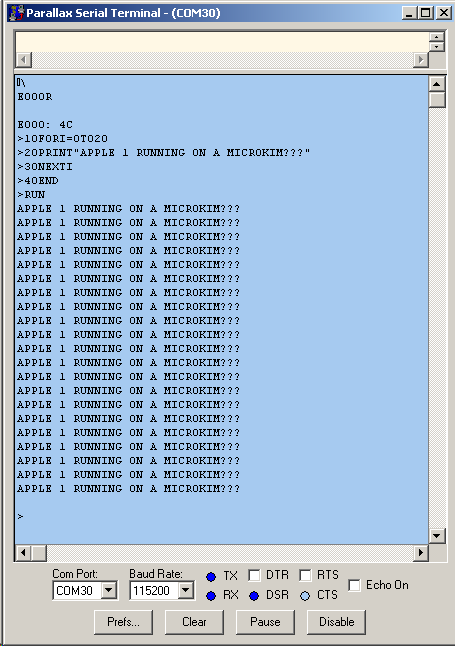
It worked! I could type commands on the Woz monitor, write programs in Basic and use Krusader to write short Assembly programs to do stuff like send the alphabet to the serial port. All using the Woz mon subroutines and the Propeller serial port of course: all the hardware on the MicroKim except the 6502 was disabled.
That meant that I had everything connected correctly, the 6502 was working as it should, and the Propeller code that I had to modify to work with an incoming clock signal instead of generating its own, was working too. That was a good beginning.
KimStar Experiment 2: "Kimple1"
The next step was to check if the on-board RAM, the 6532 RIOT chip and the address decoding hardware were all working okay. To do this, I wrote a small piece of code that would enable the MicroKim address decoder for addresses $0000-$1FFF. I reinstalled all the chips (RAM, RIOT and EPROM) and powered it up. The Propeller was still emulating the Apple-1 PIA and emulated the Apple-1 ROM image, but the lower 8K of the 6502 address space was all taken up by real hardware. I called this setup "Kimple1".
Because the Apple-1 ROM image was still mapped into the upper memory area, the system still behaved as an Apple-1, but it was using the onboard RAM. I could also verify using Woz Monitor that I could read and write the RAM in the RIOT chip. One thing I couldn't do anymore was to use Krusader, because it really doesn't like to run in a system that only has 5K RAM and it doesn't check how much RAM it has. But one thing I could do was to use Woz mon to dump the MicroKim EPROM to the Propeller's serial port!

Hmmm. This may look okay at first glance, but if you compare that to what it should be, it's very very wrong.
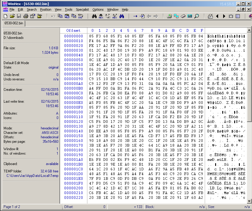
I was afraid that my EPROM had been partially erased (where bits had been changed from 0 to 1) by stray sunlight, but it was worse than that: some bits were changed from 0 to 1 and some others were changed from 1 to 0. It may not look like it in the pictures above, but that EPROM was fubar. Well, that explained why my MicroKim wasn't working without help from the Propeller, I guess.
By the way, a few weeks later, I ordered the Superboard III from Briel Computers, and when I told Vince Briel about the problem, he kindly included a replacement EPROM for my MicroKim at no extra charge. Thanks Vince!
KimStar Experiment 3: MicroPle1
So I found out why my MicroKim wasn't working and I had a Propeller attached that could emulate the correct ROM image in the right place. Actually it would have to map the MicroKim image in two locations: $1800 to $1FFF as well as $F800 to $FFFF.
It was easy to change the code that enables the MicroKim's address decoder so it would only activate for addresses below $1800 instead of below $2000. That way, the on-board EPROM would always be disabled but all the other hardware would still be active. That worked, of course.
But I thought it would be more fun to do something else which I called MicroPle1. I kept the Replica 1 ROM in upper memory, but I made the Propeller program change the reset vector to $1C22 at startup time. This is where the KIM-1 ROM's reset vector would point to.

The 6502 now ran the code from the KIM ROM image, and the displays lit up. I hadn't seen this for a long time! I could also connect my computer to the MicroKim serial port and it worked too!
The fun thing is that this was now a unique hybrid between a MicroKim and an Apple-1: in the picture above you can see the KIM monitor show the first byte of the Woz mon code at $FF00. I could hit the Go button on the MicroKim keyboard and the serial port on the Propeller (where the Apple 1 PIA was emulated) would come alive. And if I would want to go back to MicroKim mode, all I would need to do is type "1C22R" on my serial terminal connected to Woz mon.
So what's next?
One problem with this setup is that the connections to the MicroKim keep me from connecting the 32KB expansion board that I also own. Briel Computers also has an expansion board with a second 6532 which has additional expansion headers. I don't have this board but I'm thinking of ordering it. I'm also thinking of designing a board with a 32KB memory expansion (or more), the Propeller and a video output.
The Propeller makes it possible to to emulate other hardware too, for example it could emulate extra ROM holding useful sofware (such as Microsoft Basic).
The EEPROM that stores the firmware for the Propeller can also be used to store a MicroKim software library, which can be loaded directly into memory via a menu that the Propeller can show on a screen or on a serial port. Or it can be used to emulate a paper tape punch and a paper tape reader as if they are connected to the MicroKim serial port.
The possibilities are virtually endless!