Preface
Just like every other hacker on the planet I jumped on the esp8266 bandwagon, ordering my first batch on Aliexpress a few days after it first hit Hackaday. As usual, life happened and the modules ended up in a drawer for a couple of weeks. With (at that time) limited info on the web, the learning curve was rather steep. I put down a few of my learnings below, skip if you managed to get a module to work already. Don't skip if you haven't.
Besides all the quirks I ran into, I noticed that the standard code examples all work but not reliably. Usually it's 1. find an access point, 2. connect to access point, 3. create connection, 4. send and receive data, 5. close connection. Usually it works, sometimes it doesn't. When it doesn't, reboot by pressing reset on the arduino, yank reset on the module, a combination of the two, or just power cycle. No problem on a lab bench, big problem if you want to do something useful, predictable, and semi-permanent. So I set out to come up with a library that would be as fault tolerant as possible. I didn't achieve all my goals but enough to have something that has been running in a non-ideal environment for a few weeks now without any problems. Sometimes good enough is good enough.
Stuff I ran into
1. Power supply. Most people say that a dedicated power supply to the module is recommended as feeding it off an arduino for example may be problematic. I think those people are wrong. It shouldn't be a recommendation but a requirement. Unless your arduino can reliably supply 500mA without droops or noise (most can't), don't bother. It will work well enough to sucker you into believing that you may get away without a dedicated power supply but you won't. So either make sure you have one of those boards that can supply a hefty current (don't assume, know!) or just get a stabilized 3.3V power supply. Buy, borrow, or build (don't steal) one. I built several using an LV1113 connected to a 9V wall wart rated for 1.0A. Most of my problems disappeared once I had a stable power supply.
2. Pull up resistors. Make sure RST, GPIO-0, and CD_EN are pulled high. I use 4.7k resistors. Without it, stuff becomes flakey. Unfortunately not flakey enough to be immediately noticeable.
3. Level shifters. Part I.: The ESP-01 module I use (as most other modules) is a 3.3V devices. Ideally interface to a 3.3V MCU. If that's not possible, you need level shifters. My arduinos (Uni, mini, nano, and breadboarded IC) all have 3.3V capable inputs so no shifting from 3.3V to 5V is needed. Good. For the RX input, I use a 330Ohm resistor between the esp8266 RX pin and MCU TX pin with a 3.3V Z-diode in reverse. That works well.
4. Level shifters: Part II.: Reset is a bit harder. If you want to drive reset from a 5V device you can use the Z-diode/resistor combination also. However, you can't have a pull-up resistor to 3.3V because that will give you a circuit that will present as a 1.8-2V level at the reset input. Three options: 1. Get rid of the pull up resistor. As long as the MCU output pin is driving either 0 or 1, you're good. During bringup, or with a loose wire, or no connection at all, all bets are off. Works but not recommended. 2. Get rid of the pull-up resistor from 3.3V and pull up the input of the Z-diode/R circuit to 5V. That works fine. 3. Use a pull-up to 3.3V as before, get rid of the Z-diode/R circuit, and configure the arduino pin as an open-collector (OC) output. Which is a bit difficult given that the arduino doesn't have OC outputs. Except you can fake them in software. To drive a 0, set the pin as an output pin and drive a 0. To drive a 1, set the pin as an input pin and let it float. The pull-up resistor makes sure the RST pin sees a 1. Won't work if you use some pre-packed library but works fine with your own code.
5. Firmware: The stock 0.8.x firmware is no good. Update to 0.9.2.2. However firmware changes aren't terribly backwards compatible. Typos in response messages are fixed and new ones are introduced....
Read more »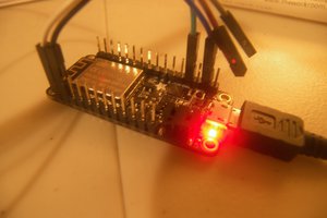
 Alexander
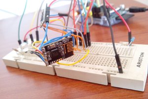
 Rui Rex
 Int-Mosfet
 Alexander Williams
in "2. Pull up resistors. Make sure RST, GPIO-0, and CD_EN are pulled high." to which pin is that CD_EN? did you mean CH_PD?
on esp-12 RST to high+4.7k doesn't allow to boot, if I disconnect, it does.