 Hacker404
Latest Status Update:
I have discovered a laminator on ebay for $60 (AUD) that has plenty of room inside and looks like it may heat to 170 - 200 °C. So it may well fit the need straight out of the box. I'm expecting it to arrive in the week starting 23 March. I have added some notes at the end of this 'details' section about the original $15 laminator and code.
I have received the $60 laminator and it looks like a cost down version of the one used here - http://hackaday.io/project/3363-apache-al13p-laminator-one-pass-pcb-toner-xfer
It has a few bends where it shouldn't and moves around a bit when the PCB goes through so I will pull it apart and take some pics. It actually will work straight out of the box with max heat setting.
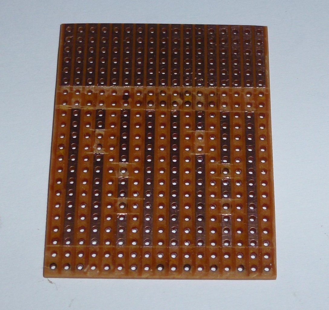
I am working with strip board because well - I don't have a fuser for toner transfer lol.
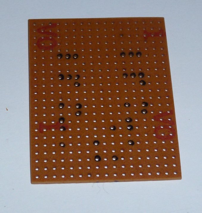
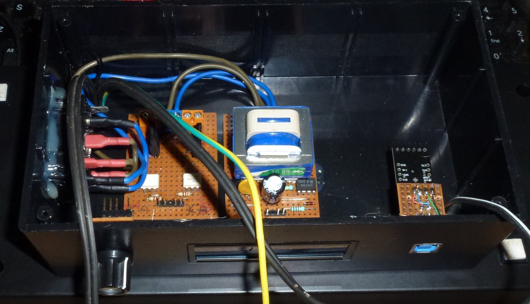
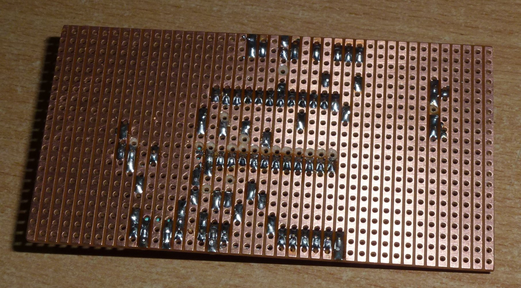
I started a power control board to control the heater and motor -
Mark out parts -
Done -
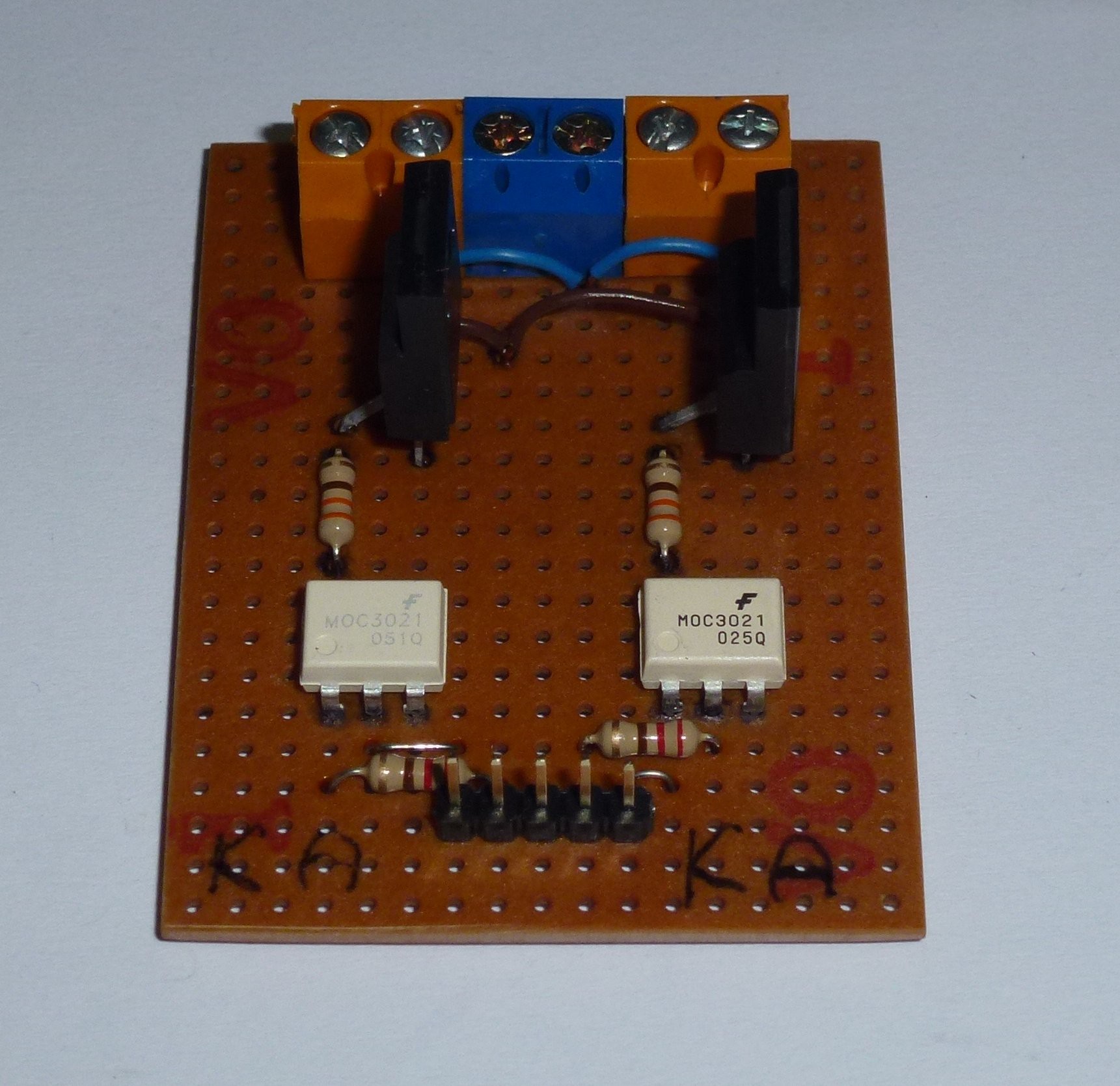
Just a couple of opto-couples (MOC3021) and TRIAC's (BT137).
I need a power supply but because of the synchronous motor this laminator has, I also needed a reference to sync to mains frequency (more later).
The power supply -

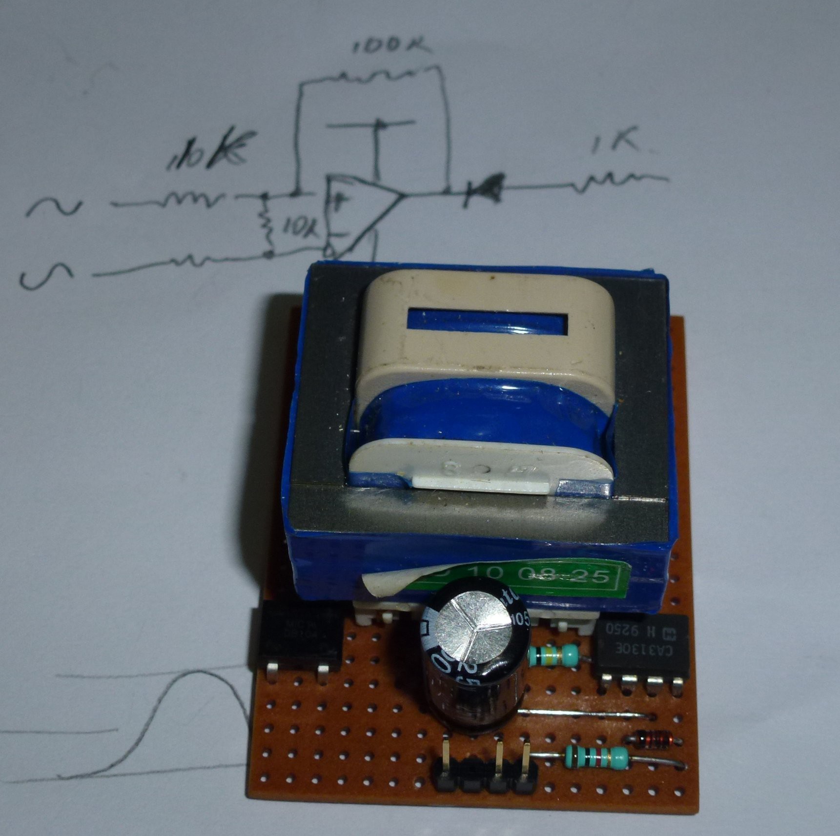
The chip on the left is just a bridge rectifier. The chip on the right is a op-amp (CA3130). It is to generate interrupts to the micro controller in sync with the mains voltage. I chose this op-amp because it is a low voltage single rail chip. It also has a voltage reference that I didn't use.
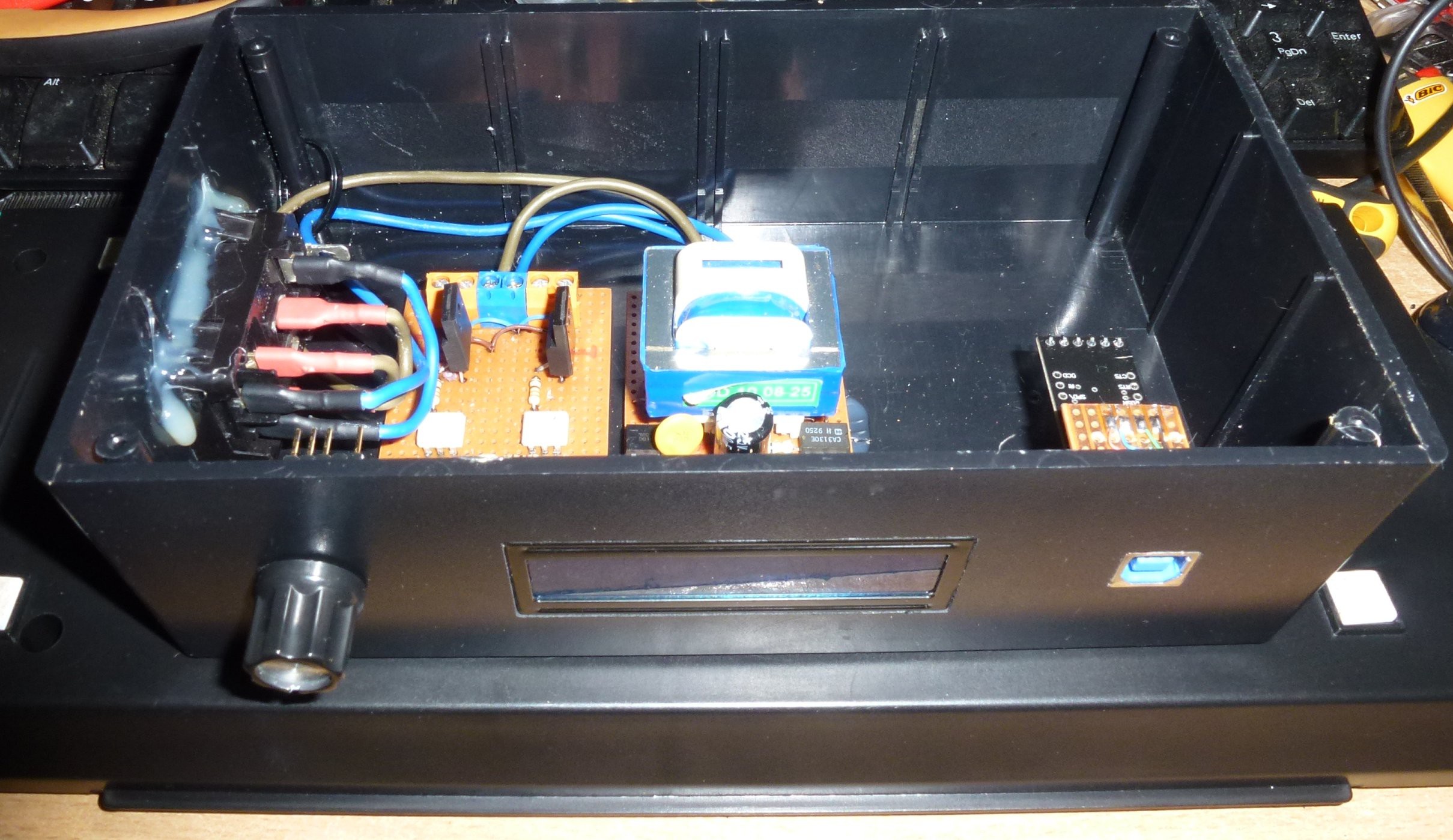
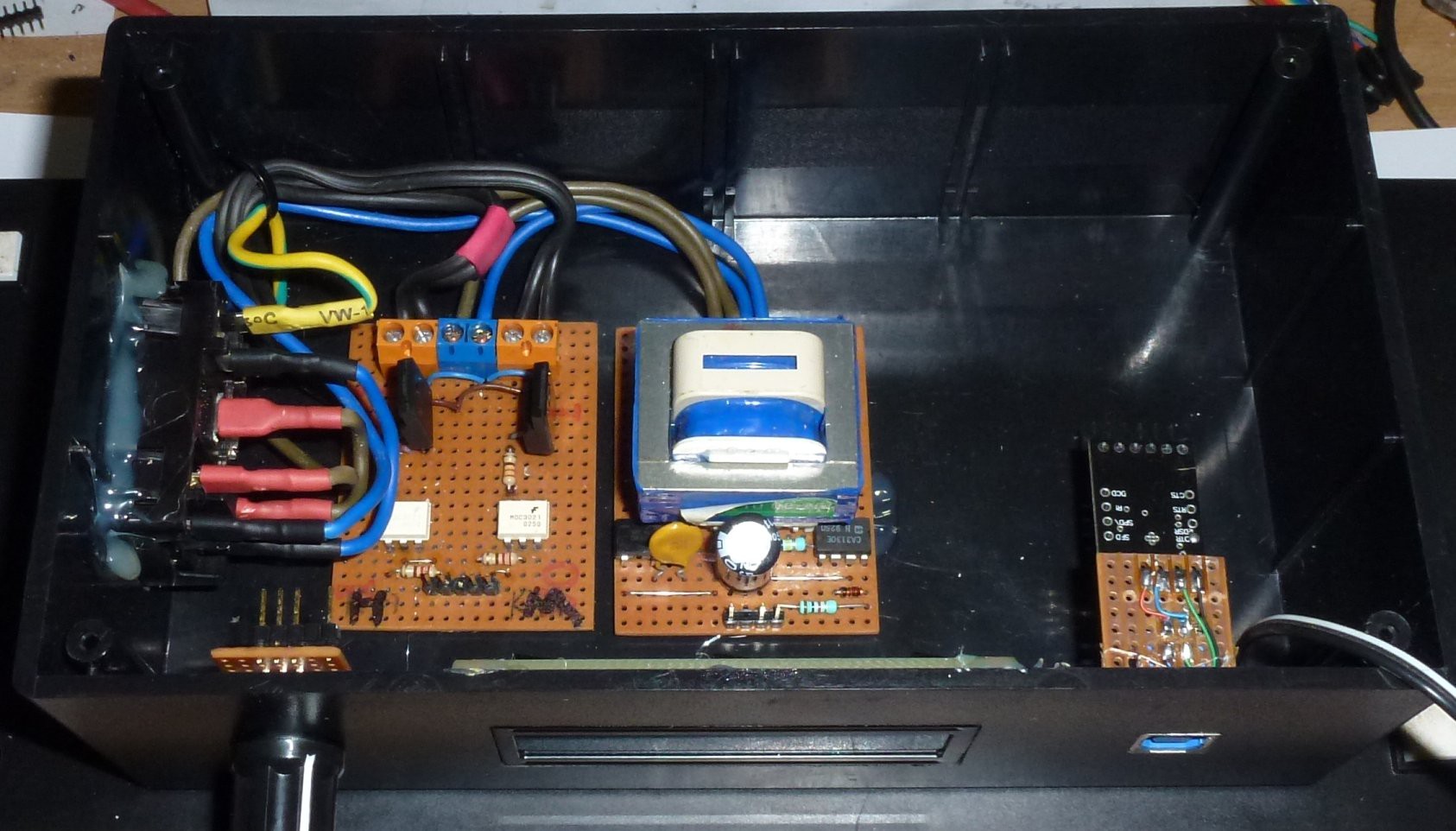
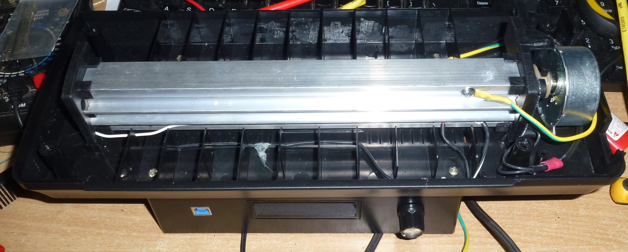
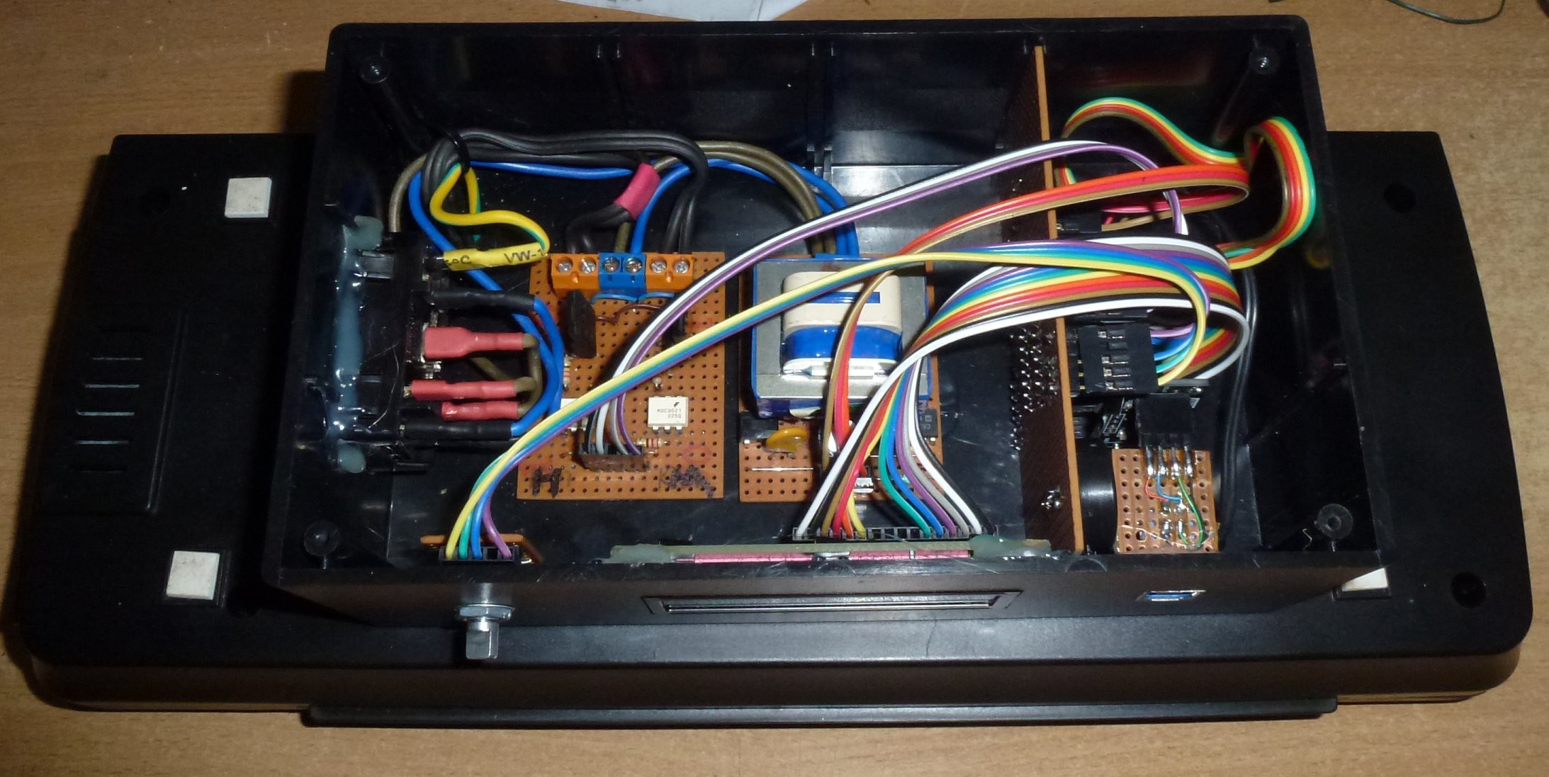
There wasn't any room for circuitry in the laminator so I decided to attach a box underneath it.
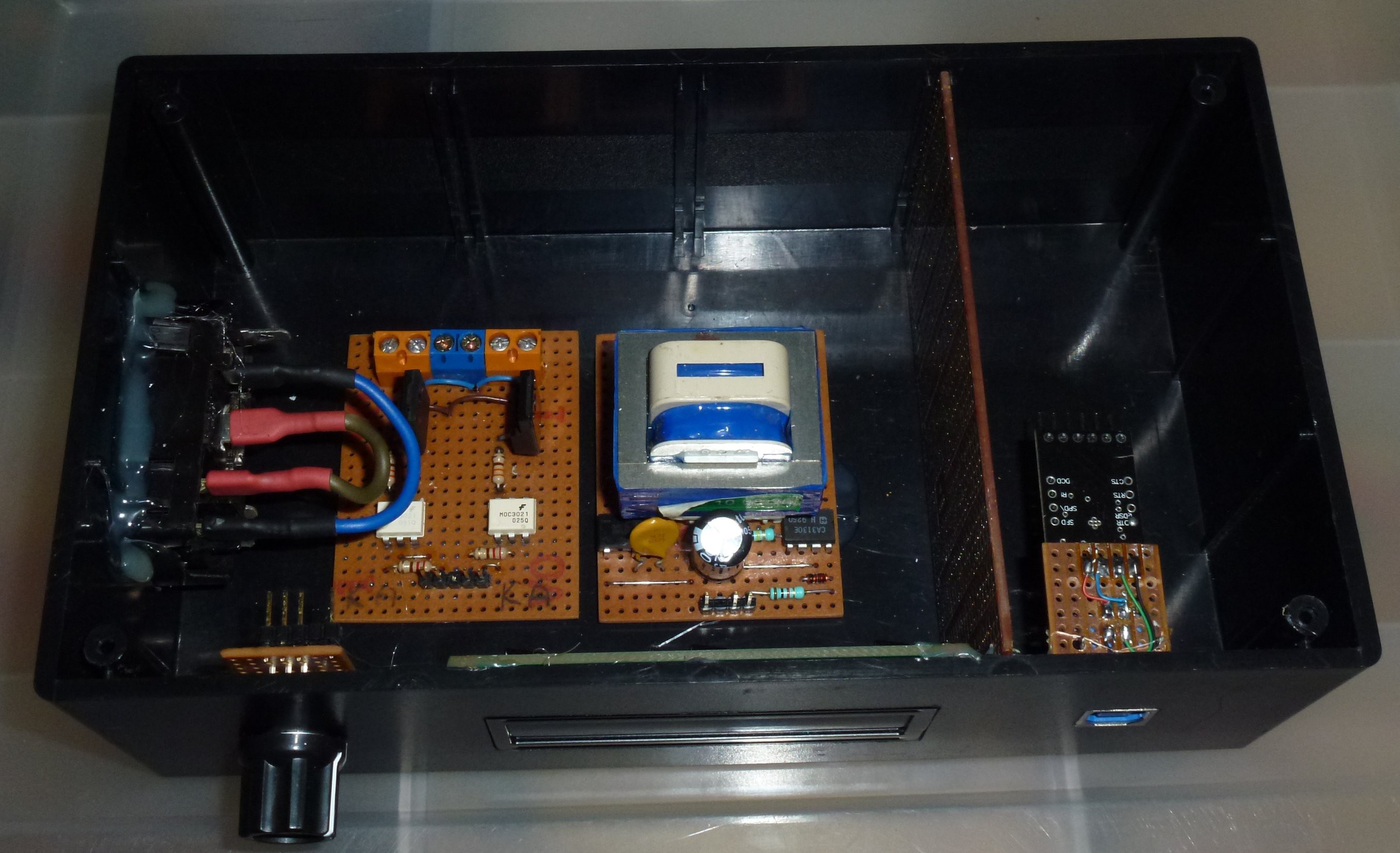
I also added a USB port for programming. A rotary encoder / switch for input and a LCD (1602) display. I glued the Mains voltage circuit boards in place for safety reasons. I didn't want them moving around and bumping the low voltage circuitry.
Then screw the box to the bottom of the laminator.
Then I did the mains wiring, keeping it neat.
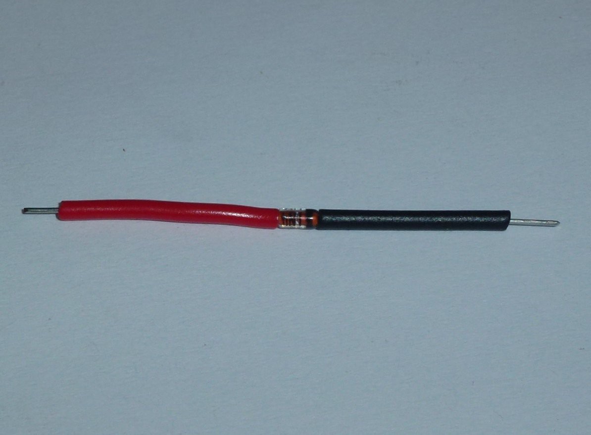
I bought some PTC temperature sensors on ebay but they where too small to mount so I decided to use a common diode (1N4148) as a temperature sensor as the junction voltage will decrease as temperature increases.
I wrapped it in foil and then pushed into the heater housing of the laminator.
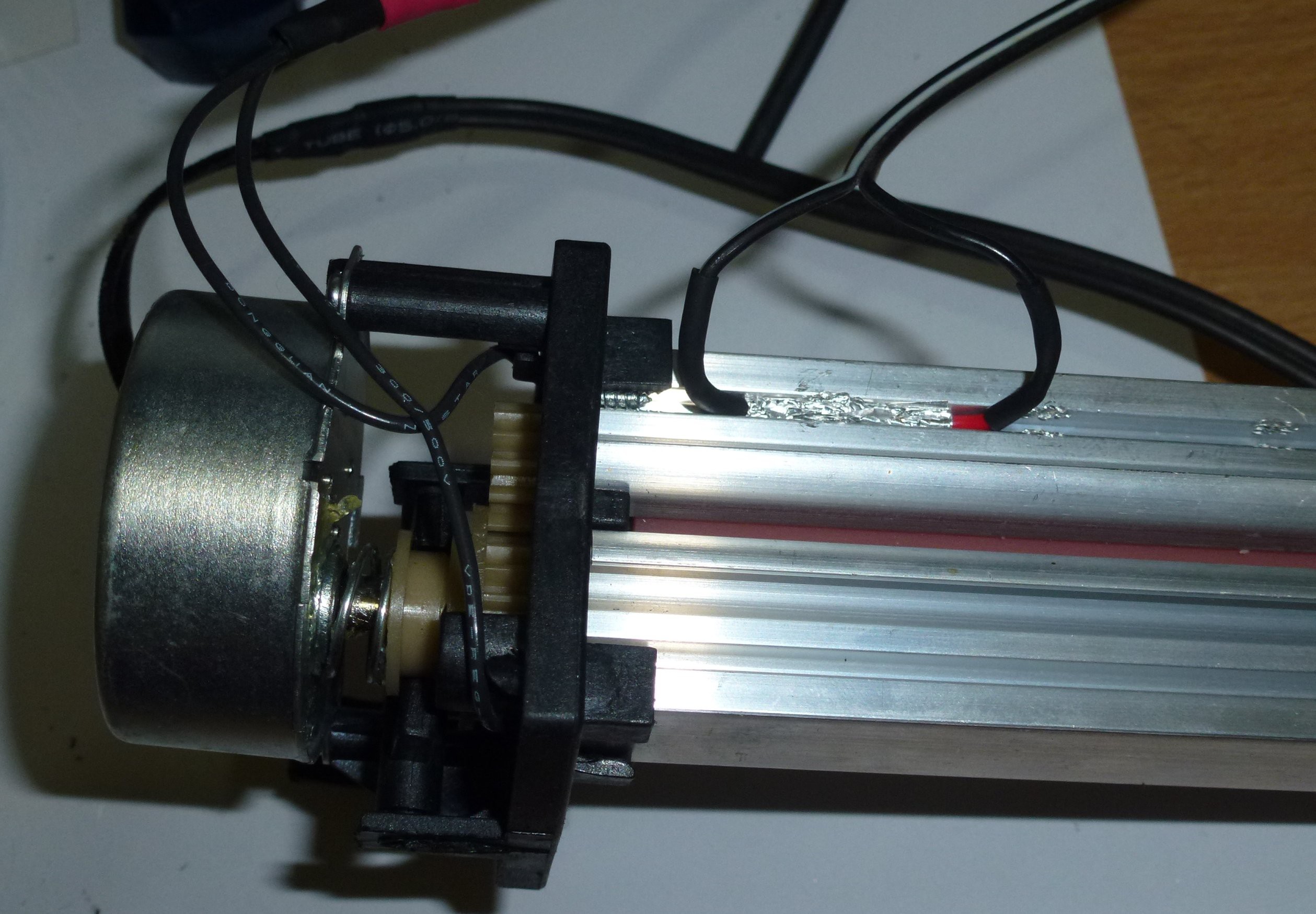
I wasn't happy with the fact that the original laminator was a double insulated device. For safety reasons you should never push anything conductive into a double insulated device like ... well a copper laminated PCB! So I earthed the metal parts in the laminator: heater and motor.
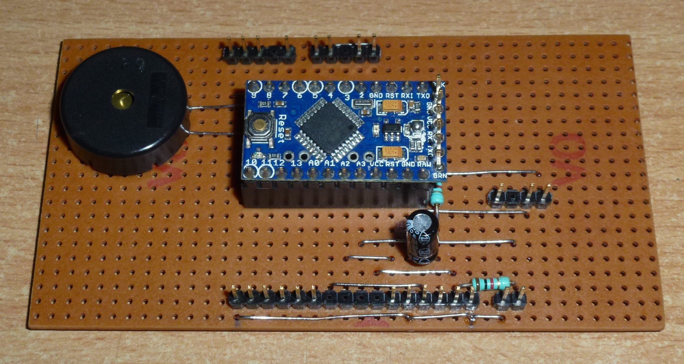
Then I had to build some brains for it. I cheated and used a Arduino Pro-Mini. Fuseduino? Still all on strip board.
Then all in the box.
Then the problems started ... I mean I started coding.
My first problem was that I was getting erratic interrupts from the power supply board. I didn't know what was going on except that some times the interrupts were as close as 8 uS apart and sometimes they were at 20 mS apart as they should be.
I don't have a scope so I wrote some code to monitor the interrupt pin, store the data into an array (at high speed) and then send it through the serial port at a lower speed. I then put the data into some JavaScript and used a browser to graph it.

What I found is that I was getting 4 major transitions per cycle and a lot of noise triggering near the the major transitions.
I then realised that I had left out one resistor on the power supply board that was now glued into place.
After considering putting parts onto the glued in board, I decided to try a software fix.
It was dead simple, I just had to ignore any interrupts that were less than 3/4 of a cycle after the last. ie less than 15mS (for 50 Hz).
I then found that I could slow the motor by giving it 10 cycles of power and then stopping the power for 'x' cycles. The motor is synchronous so this is the only way to regulate speed.
After some experimenting with code for the heater / motor / sensor, I had an oops moment when I coded for the heater to be on when the motor wasn't running.
And ...
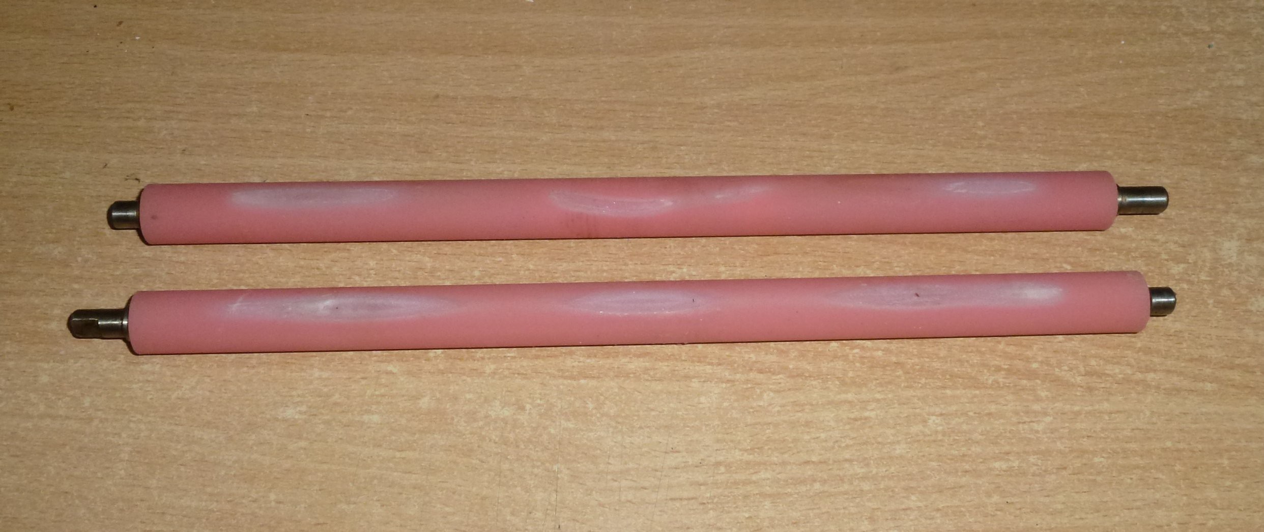
... I burnt the rollers! After this the motor would jam when the rollers were heated to about 150 °C.
I don't know if the motor jam is because of friction (burnt rollers) or because I don't have a snubber network in the TRIAC driver stage for the inductive load of the motor.
So far I was just turning the heater on and off (GPIO) so now I will try to use PWM and see how it goes.
In the original design the heater runs at 100% power up until it reaches 120 °C and then runs at 50% power up to 140 °C. For (re)fusing I need it to get to about 160 °C to 180 °C(max).
Today I went and bought another laminator (exactly the same) as they're only $15.
Soon I will post my "Melting laminator parts" version 2.0
Update: 21 March
Before I leave this cheaper laminator, I thought I would add some notes about how the code worked (or did not work lol).
Motor -
I used TRIACs to drive both the heater and the motor. Not having a snubber network to in the TRIAC drive for the synchronous motor didn't seem to make any difference. Perhaps the load/inductive attributes of the motor are not so great.
It's not a normal practice to try to control the speed of a synchronous motor. It is often said that this cannot be done. For example - if you were to try to use PWM then you would reduce the torque and not the speed ... at least until it stalls from lack of torque.
My approach was to use the AC mains to interrupt the micro controller at the mains zero point crossing of the mains voltage. This was done with a simple op-amp on the secondary side of the PSU transformer so it mean that this approach cannot be done with a switch mode power supply.
The other advantage of switching power on or off at the zero crossing point is that it generates far far less electrical noise or RF interference.
The intent was to turn on the motor for a certain number of cycles and then off again. This stop-start cycle would effectively reduce the motors average speed.
There are three variants of the small synchronous motor used in this laminator.
1) The most common is the one that drives the turntable in your microwave oven. It will start and rotate in a random direction ... either clockwise (CW) or counter clockwise (CCW).
2) A variant that rotates clockwise.
3) A variant that rotates counter clockwise.
It seems (from listening / watching) that they are all basicly the same and the specific direction motors have some sort of mechanical brake that prevents it from turning in one direction. Because it is prevented from rotating in that direction, it will then start rotating in the desired direction.
This mechanical break needs some rotation in order to take effect. I found that it needed at least 10 cycles at 50 Hz to work and about 20 cycles to be reliable.
I didn't measure the exact number of cycles so I will write a hypothetical explanation.
Lets say it takes 2 cycles for the break to reverse direction. If you give the motor 2 cycles and it randomly starts in the correct direction then it will rotate by two cycles but if however, it starts in the wrong direction - it's net movement will two cycles in the wrong direction because the brake has not yet activated.
Now lets give it 4 cycles - resulting in either 4 cycles or zero cycles movement (two cycles backwards until it breaks and then 2 cycles forward).
Then 8 cycles give either 8 cycles or 6 cycles
And then 20 cycles gives 20 or 18 cycles movement which isn't so bad a disparity.
This method of pseudo speed control is viable but for this application you need to code so that the heaters are off whenever the motor is not turning or the rollers will burn.
Now to the heaters -
I was intending to use much the same method of control for the heaters but this wasn't to be. ie - heaters on or off for 'x' cycles. The problem is that the mains frequency does not offer enough time resolution.
To explain - when I converted to PWM I was seeing PWM values as small as 1 being output by the regulation code. To achieve the same with mains cycles then you would have to have the heater on for one cycle and then off for 255 cycles. This is about 5 seconds off and in that length of time the heat will vary and need to have re-calculated many times or it will be very inaccurate.
I measures the delay from when the heater is switched on until when the sensor starts changing and it was about 15 seconds. Some of that time is probably because I wrapped the sensor (1N4148 / 1N914 diode) in aluminium foil wrap. I later noticed that the foil was sticky so I am guessing that it was coated in a thin plastic film.
15 seconds is a very long time in a feedback loop and there were other issues as well.
The sensor is on the heater housing and not the rollers so the system would need a very long time to stabilise.
The other issue is small rollers that have a low thermal mass.
General issues -
This $15 laminator doesn't have any room in it for circuitry and a power supply. Even with a switch mode PSU you would be flat out fitting it inside and if you did the it would most likely fail due to the heat.
The synchronous motor is mains power so it is hard to control with any accuracy.
I don't know anything about PID but I did try PID and I couldn't get it to cope with the 15 second feedback loop time. I did however burn the rollers so at least I got a good laugh from the 'fail'.
The temperature sensor really needs to be on the rollers and not the heater housing.
Notes of interest -
The diode as a temperature sensor works OK. It's has the issue of being small but that may be an advantage in some situations. I was going to install a DS18B20 IC temperature sensor to measure the ambient temperature on start up. I have not verified this but I expect the the temperature slope of the diode would be much the same if not identical from one diode to the next. If this is the case then it is only the offset that is different. Knowing the temperature at start up (ambient) would then allow some rough calibration of the sensor. I will test this later on. In the mean time I have ordered some cheep ($1) PT100 sensors from ebay as they are larger.
Synchronous motor control is a pain. A much better solution would be a low voltage DC motor or a reversible induction motor.
The new laminator on order -
It's A3 so I am hoping there is more thermal mass in the rollers.
There is room for circuitry inside though I may have to install a thermal barrier.
It may even have a DC motor if I am lucky.
I will update and post pics when it arrives.
PS: If you want any code examples or schematics then let me know.