 Artem Kashkanov
Motivation
DekatronPC is next project after BrainfuckPC relay computer.
I made some architectural mistakes in relay computer and want to create more clear an much more insane device.
Overview
Harvard architecture with separate memory for code and data
30000 8-bit cells.
Decimal data representation
Instruction Set
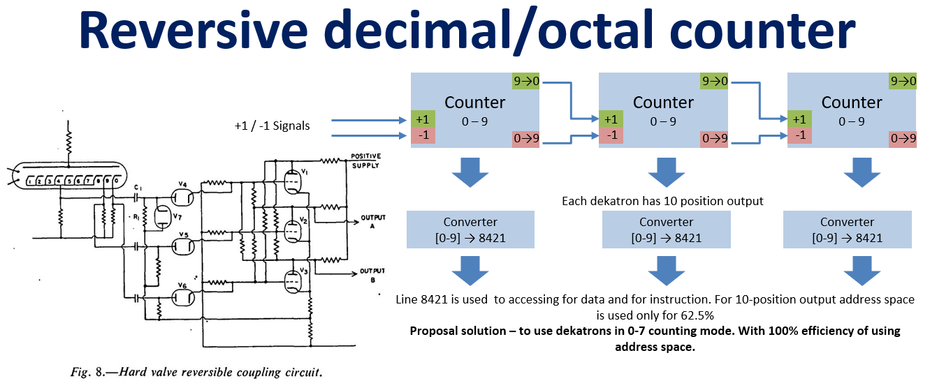
Main point - pure brainfuck. If BrainfuckPC have fully-functional 16-bit adder and can ADD/SUB any 8-bit of 16-bit CONST, DekatronPC due to dekatron feature can do only +1 and -1.
| DekatronPC instruction | brainfuck equivalent | description |
| INC | + | Old value from current memory cell is loaded into dekatron counter, incremented and stored back |
| DEC | - | Old value from current memory cell is loaded into dekatron counter, decremented and stored back |
| ADA | > | Increment number of current memory cell (go forward through memory) |
| ADS | < | Decrement number of current memory cell (go backward through memory) |
| IN | , | Read ASCII symbol from terminal and store it in a current memory cell |
| OUT | . | Write value from current memory cell to a terminal |
| [ | [ | If value of current memory cell is not zero - do nothing. If zero - increment IP pointer while the end of this loop is not founded |
| ] | ] | if value of current memory cell is zero - do nothing If not zero - decrement IP pointer while the begining of this loop is not founded. |
| NOP | n/a | Used for loop alignment |
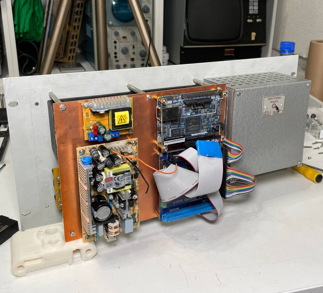
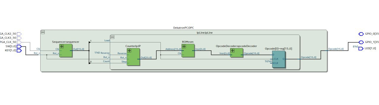
Architecture
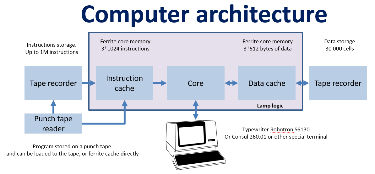
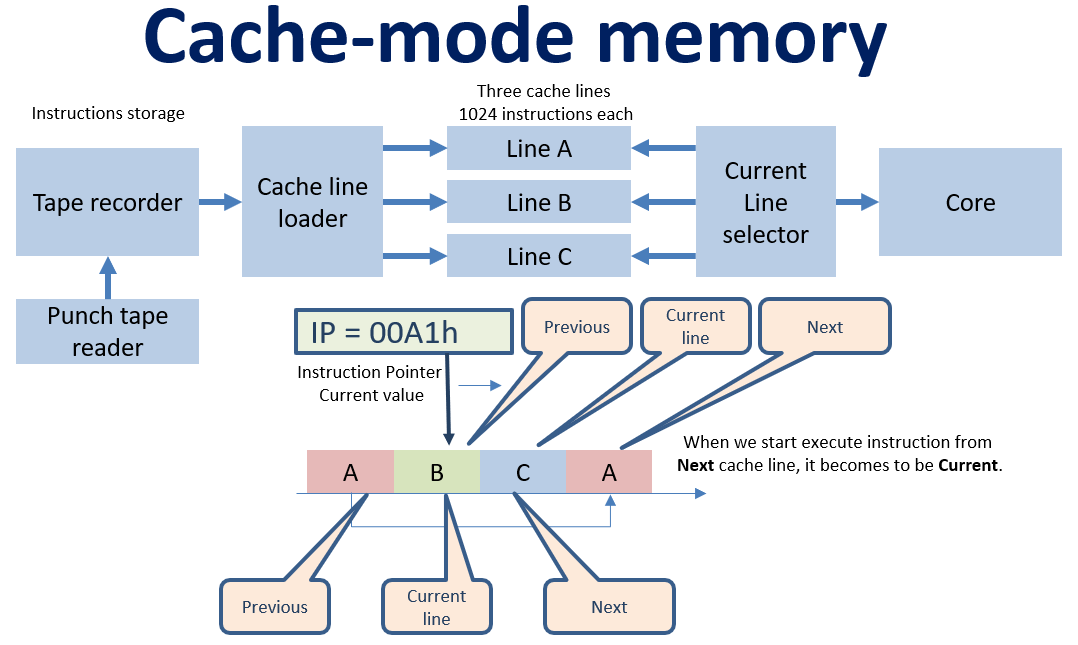
DekatronPC can be used in two modes:
- In clear lamp mode. Ferrite memory work in direct mode - when program is loaded directly to instruction memory and data memory working without any external storage. No transistors are used in this mode, but we are limited with 3KB of instructions and 1.5Kb of data.
- In insane mode. Ferrite memory works in cache mode and external storages are used for storing instructions and data. No size limitations, but outside lamp logic we can use transistors.
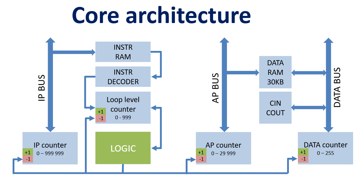
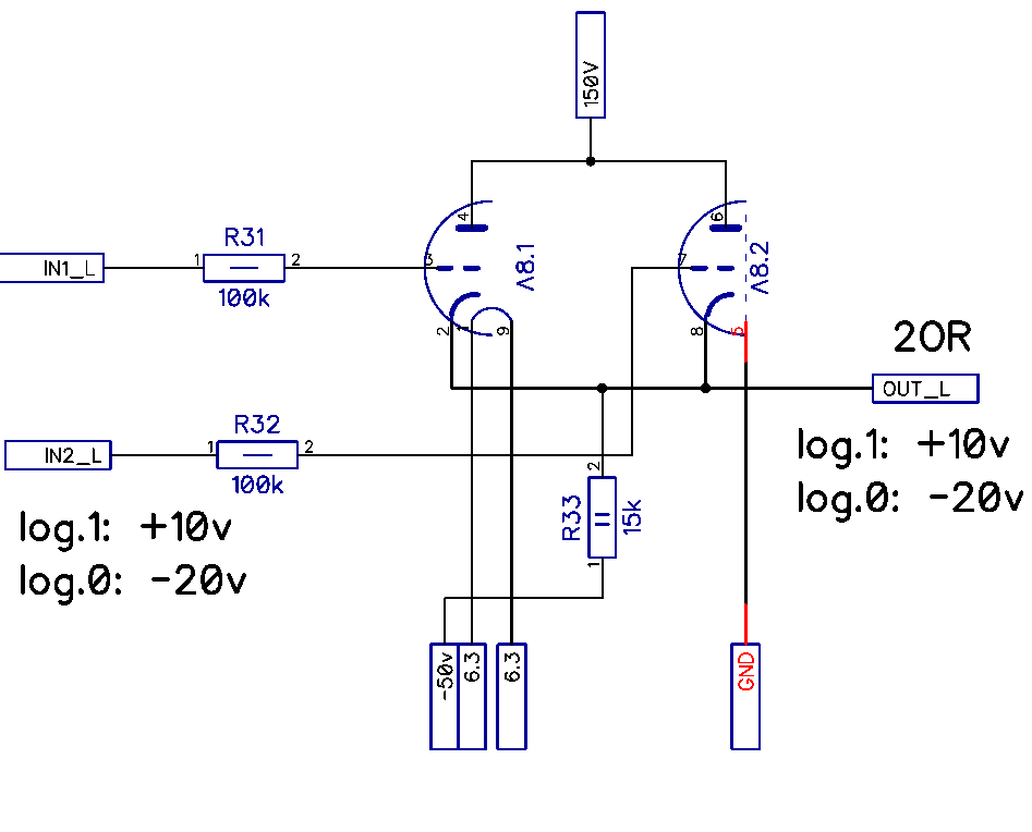
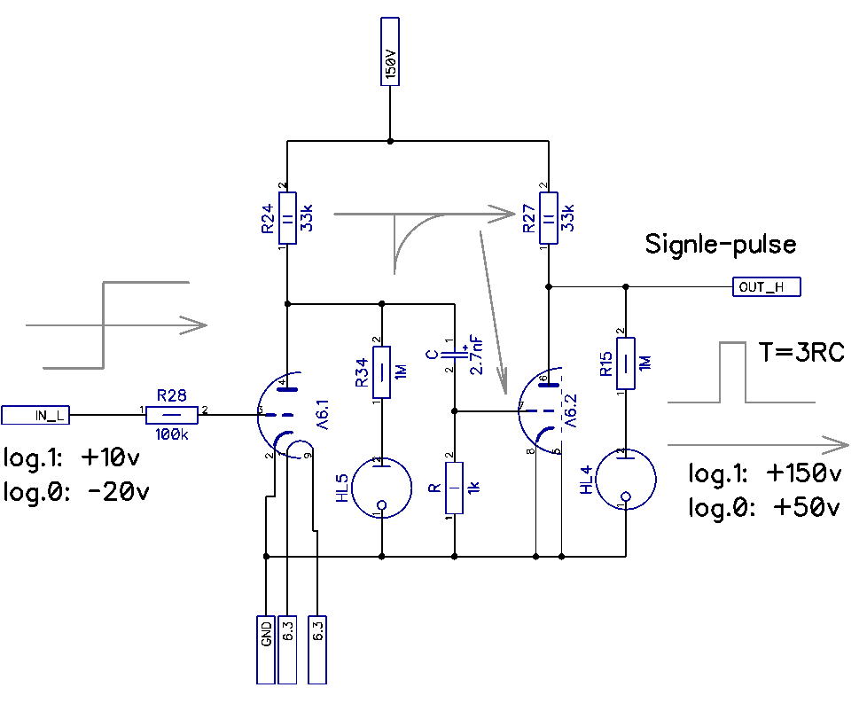
Hardware, which can support described instruction set can be implemented on four reversible dekatron counters:
- IP counter - can count from 0 to 999999 (6 dekatrons). Just represent current instruction number
- Loop level counter - can count from 0 to 999 (3 dekatrons). Used for cycles limits lookup
- AP counter - can count from 0 to 29999 (30000 memory cells ) (5 dekatrons). Just represent current memory cell
- Data counter - can count from 0 to 255 (3 dekatrons). Used for loading data from memory, modifying it, printing, reading and storing in memory
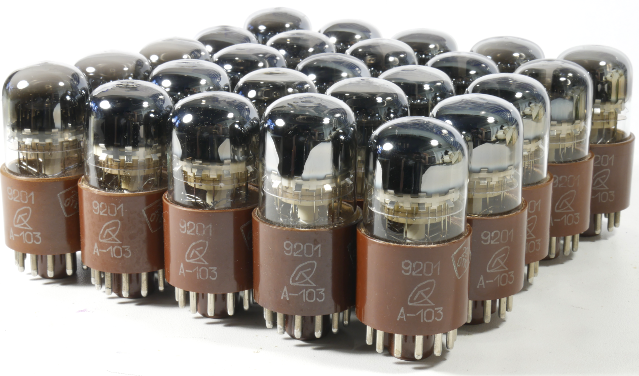
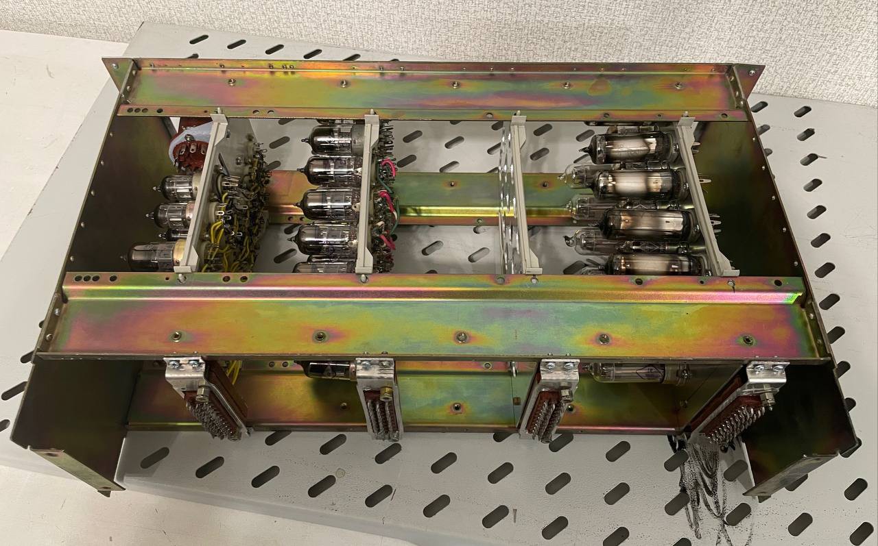
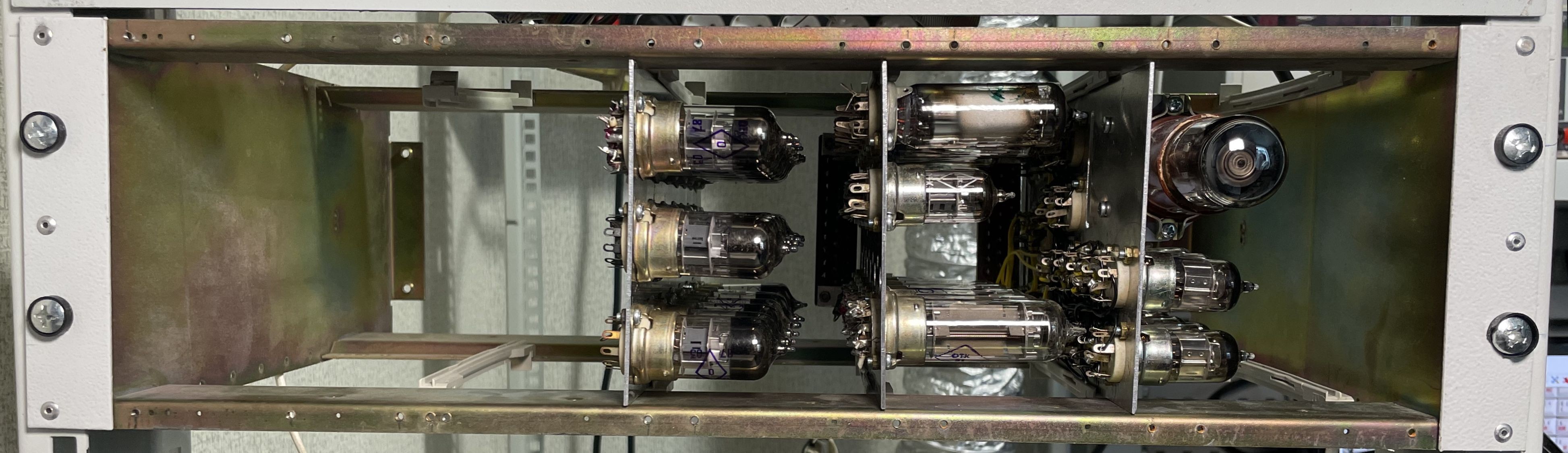
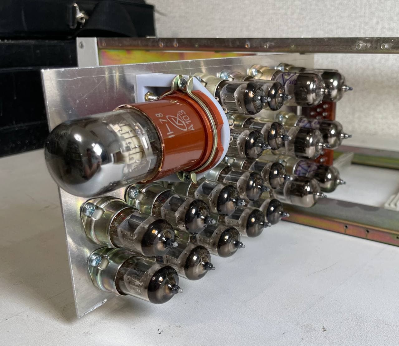
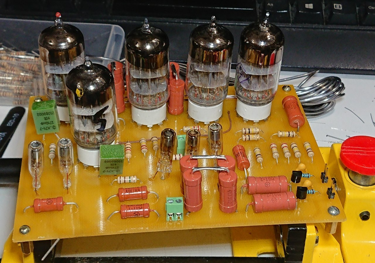
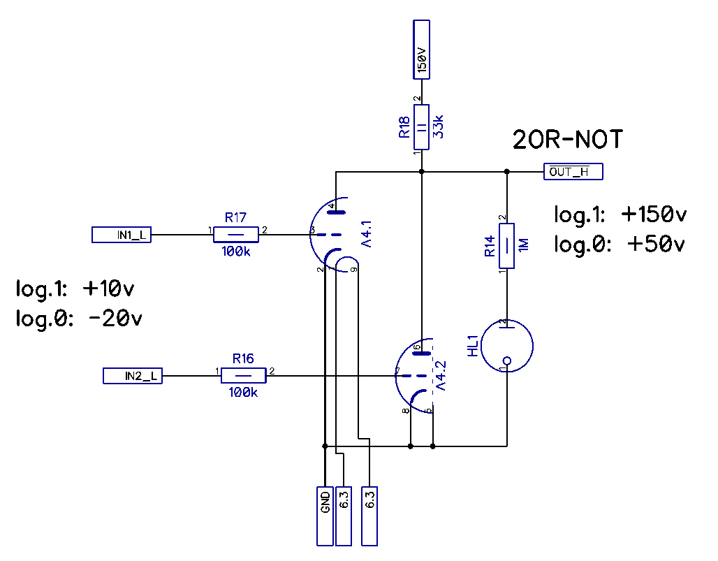
Just only 17 dekatrons are needed to make the whole device. But each dekatron require up to 10 vacuum tubes.


 Andrew Starr
 Charlie Smith
 Pavel
Pavel
Cool! Dekatrons, I remember those. Counter and display in the same tube. What's not to like? 👍