• IT lives - All devices are belong to us

    zittware05/28/2015 at 22:26 0 comments

    After attaching a I2C eeprom to the AT2LP; the PATA interface came up.

    mSATA interface is working fine with an Intel and SanDisk mSATA drive.

    Basically; all of the interfaces are working as expected including the USB muxes in the design.

    Been working on FabB of the design; correcting minor issues found. Really all I need to do is add a I2C eeprom to the PATA controller and correct the I2C eeprom on SATA. No sense of urgency here as there seems to be little interest in this design publically.

  • It lives-ish!

    zittware05/07/2015 at 05:25 0 comments

    It's been a while; but I have been debugging the design as time permits. Upon initial assembly using a hotskillet reflow in the garage; I had some issues with the Edison high-density connectors. After getting that sorted; the USB hub and PATA chip identified themselves to my netbook. putting a USB memory stick on the DD[4] interface of the hub showed that I could read/write the USB bus.

    The USB hub is seen by the Edison in "host mode" and by J16 (host computer) in device mode. I can download Arduino sketches via J16 when in device mode.

    Initial debug showed several issues.

    1) the PL2571B USB->SATA chip wasn't being seen on the USB hub. Later tracked down to a bad solder joint on the clock generator's RE17 22ohm series resistor. After fixing that; the SATA interface shows up as USB Mass Storage. I do not currently have my SSD available at my home work bench; so will retrieve it from the initial test bed tomorrow.

    2) the Cypress AT2LP (USB->PATA) chip is being seen on the usb bus; but because I didn't wire in an EEPROM. :(

    3) U36 was the wrong package; so I can't power J16 when in host mode.

    4) The U5/UE6/UE7 eeprom connections don't work because there doesn't appear to be enough bandwidth in UE6 - a risk I took in the initial design; but in retrospect was flawed to begin with.

    5) J3 - the FTDI USB debug interface to the Edison kernel had some solderablity issues around J3 - I think due to close proximity to un-tented vias near the pins of J3. Was able to workaround the issue using some detail soldering - but will need to be fixed in the final design with tenting of vias - and possibly moving some of them.

    I'm going to try and find the right package for U36 and more importantly figure out how to dead-bug rework a EEPROM to the AT2LP to see if I can get that interface online in the near future.

    The other thing which needs to be done; but is likely beyond my home workbench capabilities is to do a USB dataeye analysis to see if there is any margin in the design.

  • PCBs submitted to OSHPark

    zittware03/19/2015 at 06:25 0 comments

    Quick note to let you know that two different boards were submitted to OSH park. The first was the USB Storage Sled 4layer board. The second was a Dummy Intel Edison board (2 layers). The latter supplies 3.3V and 1.8Vs to the USB Storage Sled along with #RESET ... The idea is that cheap board would be used in place the Intel Edison Module; Allowing me to test the board using a standard pc/hub; rather than risking the Edison with wiring errors.

    The Sled was submitted to OSHPark on March 13th. The Dummy board was submitted yesterday (3/17).

  • Peer Review of Proto Schematics

    zittware03/10/2015 at 04:38 0 comments

    For the last several weeks; I've been working on a custom PCB project for my Intel Edison.

    The goals of the project is to enable expanded storage thru the SSD and temporary Swap space for the Linux and WindowsXP OSes on the Intel Edison. The PCB is a 4layer implementation which implements a modified Sparkfun Edison block form factor. Current PCB measures at 4.5"x2.15". Additionally I've included the Intel reference design for the LIPO battery charger to provide a limited UPS-type capability incase of small power outages.

    More details are available at my personal blog at:

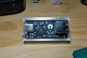
    Intel Edison: USB Storage Sled | Zitt's Blog

    I'm attaching the prototype Schematics here for peer review and comments... feel free to send me comments/questions here or at the blog. I'm taking constructive feedback thru the end of week; at which point I'm probably going to commit the design to OSHPark's PCB service. The Schematics are currently ALL RIGHTS RESERVED except where noted. Same for the Layout. At the moment; I plan to convert the project to TAPR/NCL once I've gotten the project verified as working.

    http://pinball-mods.com/blogs/wp-content/uploads/2015/03/usb_storage_sledW.compressed.pdf