 Open Green Energy
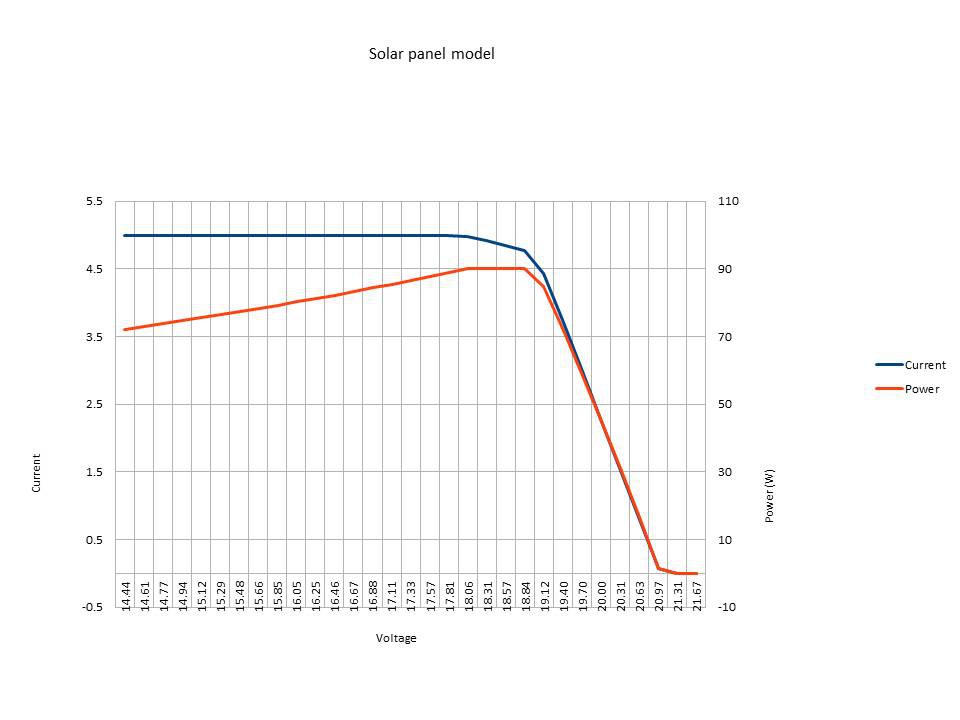
Panel model consists of a simple step-wise linear model of a solar panel.See the above figure.
1. Constant Current : up to 18 volts
2. Constant Power : between 18 and 19 volts
3. Power decline linearly to zero : between 19 and 21 volts
4. Zero Current and Power : above 21 volts
In the spread sheet attached below there are 5 MPPT models.Here is some brief description on each.
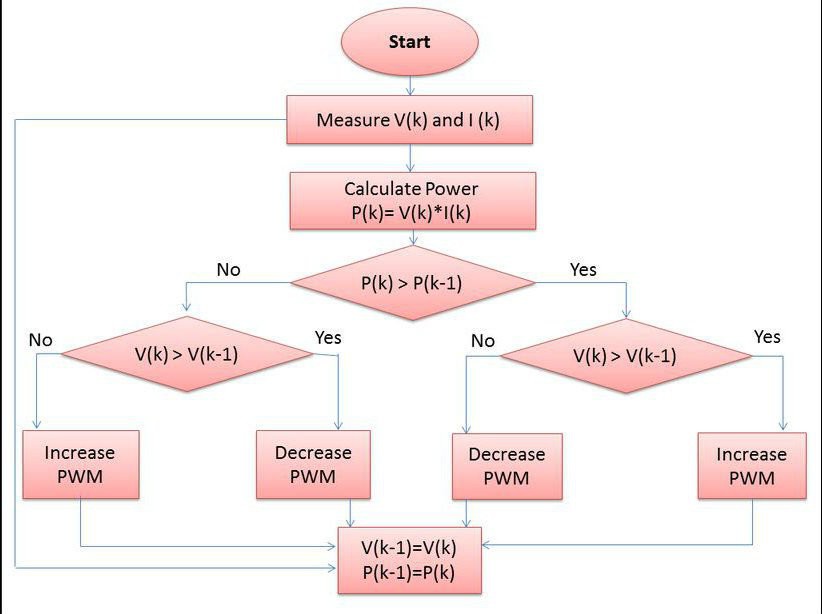
1. MPPT model 1 implements the logic flow chart as shown in above figure
2. MPPT model 2 implements the same logic flow chart with a declining panel power.
3. MPPT model 3 implements the algorithm used in the Arduino software. It is easy to adjust it for fixed or variable panel power and for various starting conditions.
4. MPPT model 4 is the same as Model 3 except that it used “<=” rather than “<” for the power test.
5. MPPT model 5 is the functionally the same as Model 4. It uses three branches on the power comparison to the previous iteration, which has the same result as the comparison in Model 4. The main difference is it uses the equivalent of the integer arithmetic used in the Arduino for calculation of PWM duty cycles.
Models 1 to 3 all exhibit similar characteristics, as follows:
They all converge satisfactorily when given a high PWM starting point (above the MPP) or a lower one with a derived voltage less than the maximum cut-off voltage of the panel (in the model, 21 V).
None of them work at all when given a low PWM starting point with a derived voltage above the maximum cut-off voltage.
The MPPT model 4 corrects this last problem by constantly increasing the PWM (ie decreasing the derived voltage) in the case of equal (ie zero) power. It will always find the MPP of the panel model no matter what starting point is used. It may take more steps than provided in the examples, but it always converges.
MPPT model 4 also sweeps the total maximum power area.
To clarify this: Models 1 to 3 when converged all oscillate at the top or bottom edge of the MPP area, depending on whether they approached it from above or below.
It seems desirable for the tracking to sweep the whole MPP area, irrespective of which direction the approach came. This would better deal with cases where the power curve had local flat spots for some reason. Model 4 does this.
MPPT Model 5 provides a tool for exploring the effect of integer arithmetic on the PWM calculations and the resultant voltages and currents.
Integer arithmetic in PWM calculations :
At the hardware level, the current software uses Timer1 to produce the PWM signal at a 20 microsecond period.20 microseconds is 320 clock cycles of the Arduino clock (which is 16 MHz, ie with a period of 62.5 ns).Because the Timer1 library uses the “Phase and Frequency correct” PWM mode of Timer1, which counts both up and down, the setting of the TOP level (which defines the 20 microsecond period) is 160. The PWM duty can be changed in units of 2 clock cycles, or 125 ns.The integer calculation of PWM runs like this (using the current software):The MPPT code uses a 16 bit integer variable “pwm” to manage the duty cycle. It runs from 0 to 100 to represent 0 to 100% duty cycle, and can be stepped up or down by 1 unit (ie 1%) in each pass through the MPPT algorithm. The Timer1 library accepts PWM duty parameter in the form of a 16 bit integer variable which runs between 0 and 1023 to represent duty cycle as a fraction of 1024.
I will use an example to illustrate how the calculations run.
As an example we start with a desired PWM duty cycle of 70%, that is the integer “pwm” has a value of 70. To convert this to an integer between 0 and 1023 to pass to the Timer1 library, the software multiplies pwm (70) by 1023 (giving 71610.The MPPT code then divides this number by 100 giving 716, which it passes to the Timer1 library. Note that 716 / 1024 = 0.6992188..., which is a small amount less than the 70% we started out with.
Note that even if we had multiplied the original 70 by 1024, it would still have produced 716 as the interface parameter value.When the Timer1 library receives the pwm duty cycle parameter, it multiplies it by the counter setting of the TOP register, corresponding in our case to 160 which is the value for a 20 microsecond period. This gives 716*160 = 114,560.Timer1 then divides that product by 1024, in our case giving 111. This is the value that is put into the register that triggers the transitions from 0 to 1 and then 1 back to 0 for the PWM signal. It will give 111/160 = 69.375% or 13.875 microseconds of 1, and the remainder of 0 in the PWM signal.
Thus, from a specified value of 70 (70%) we end up with an actual PWM duty cycle of 69.375%.This is a systematic change. As we step the pwm integer up or down, the difference changes.Thus 70% becomes 69.375%, 71% becomes 70%, 72% becomes 71.25%, and so on. The step size on the input side is always 1%, but the step size on the output side is sometimes 0.625% (which is 1/160), and sometimes 1.25% (which is 2/160).
It can happen that the ideal pwm duty cycle falls in a spot (like 70.625%) that cannot be accessed because of the nature of the integer arithmetic.
Download the Spreadsheet analysis from here
Discussions
Become a Hackaday.io Member
Create an account to leave a comment. Already have an account? Log In.