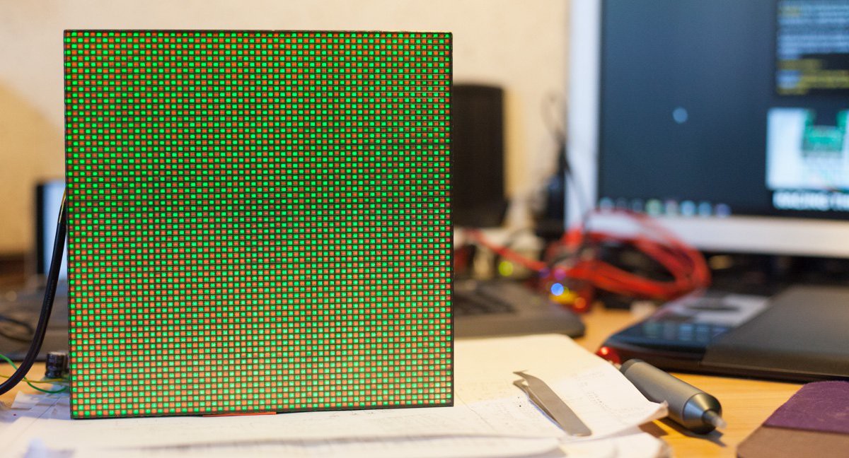
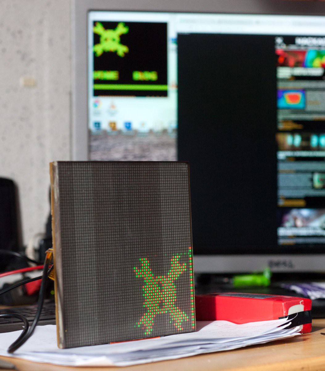
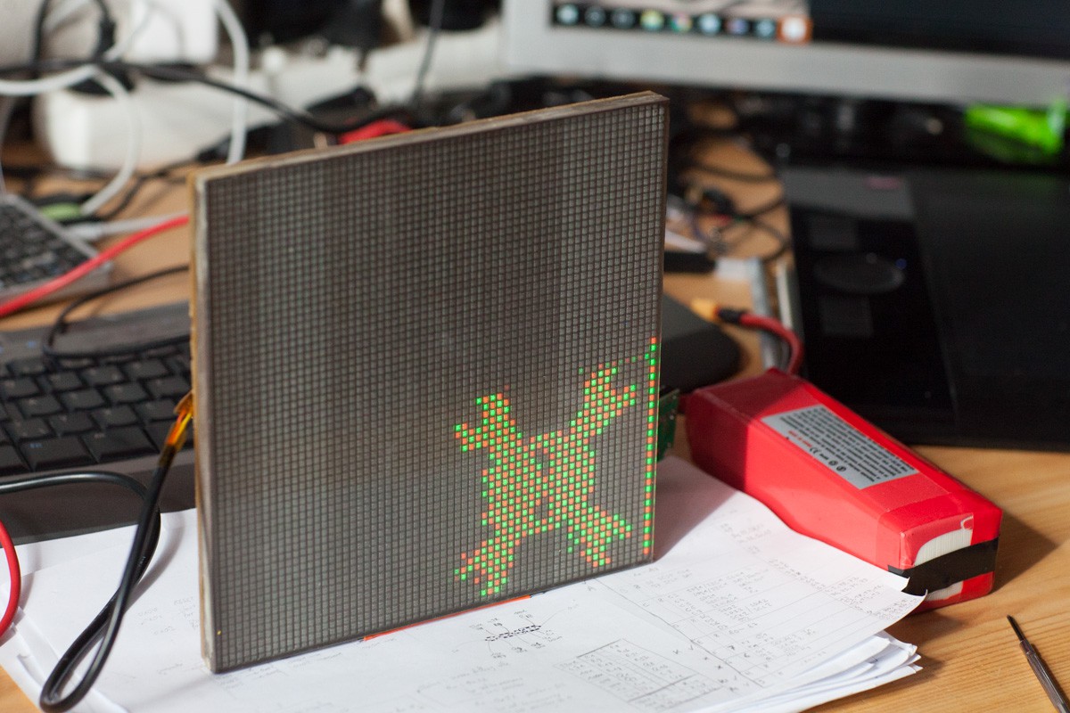
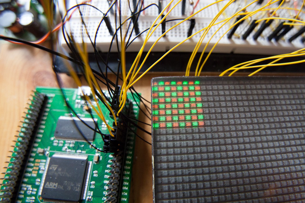
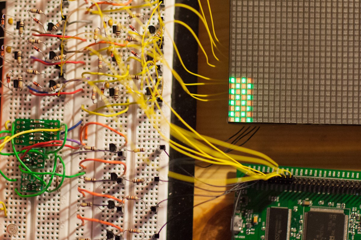
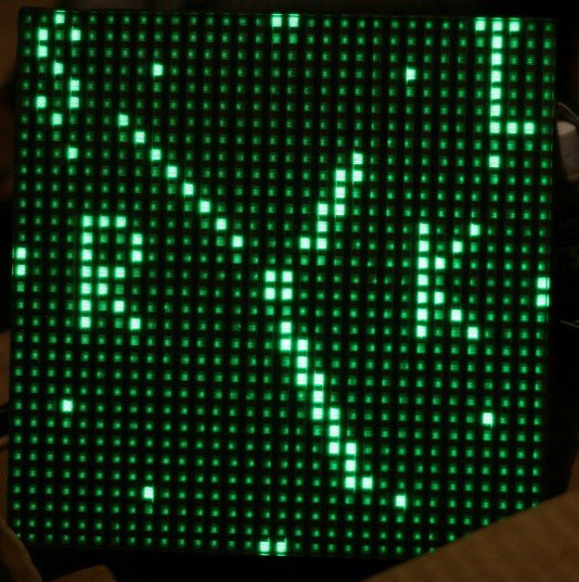
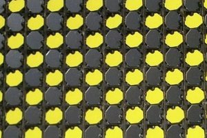
Close
0%
0%

ИГГ1-64x64M Adventure

Driving and use the ИГГ1-64x64M. High voltage vacuum dot-matrix display made in Ukraine in the 80's by Gazotron

Similar projects worth following
These display panels were lying around for quite some time now, waiting for an hypothetical interest. I decided to gave them a bit more focus after the interest shown on the dittohead's page : https://hackaday.io/page/3002-giant-nixie-panel-from-ussr
The challenge here is in several parts.
- Finding documentations and translate them.
- Driving the elements with >360 volts.
- Find a solution to drive the 128 inputs from few microcontroller GPIO
- Ultimately make it controllable with I2C/SPI/serial

There is different kind of these panels, some in a green dot 32x32 matrix, others are alternating green/orange 64x64, or even an alternating Red/Green/Blue 64x64 matrix.

I'm not sure if the light is emitted from a phosphore as the VFDs or by a gas as the Nixie tubes. 

Please expand the logs for the full adventure! 
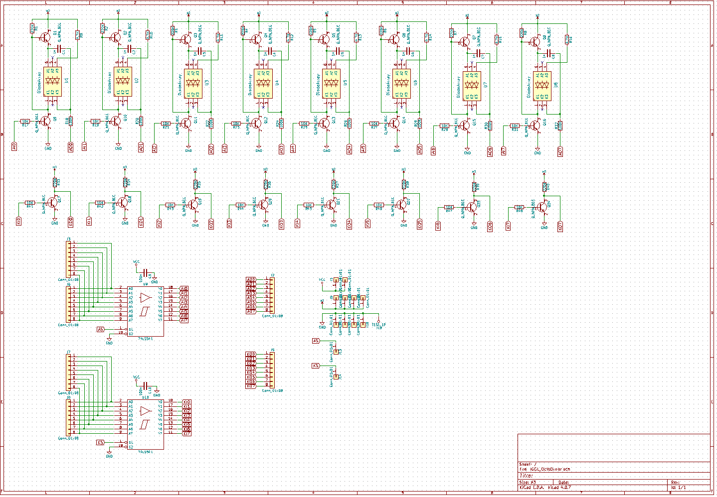
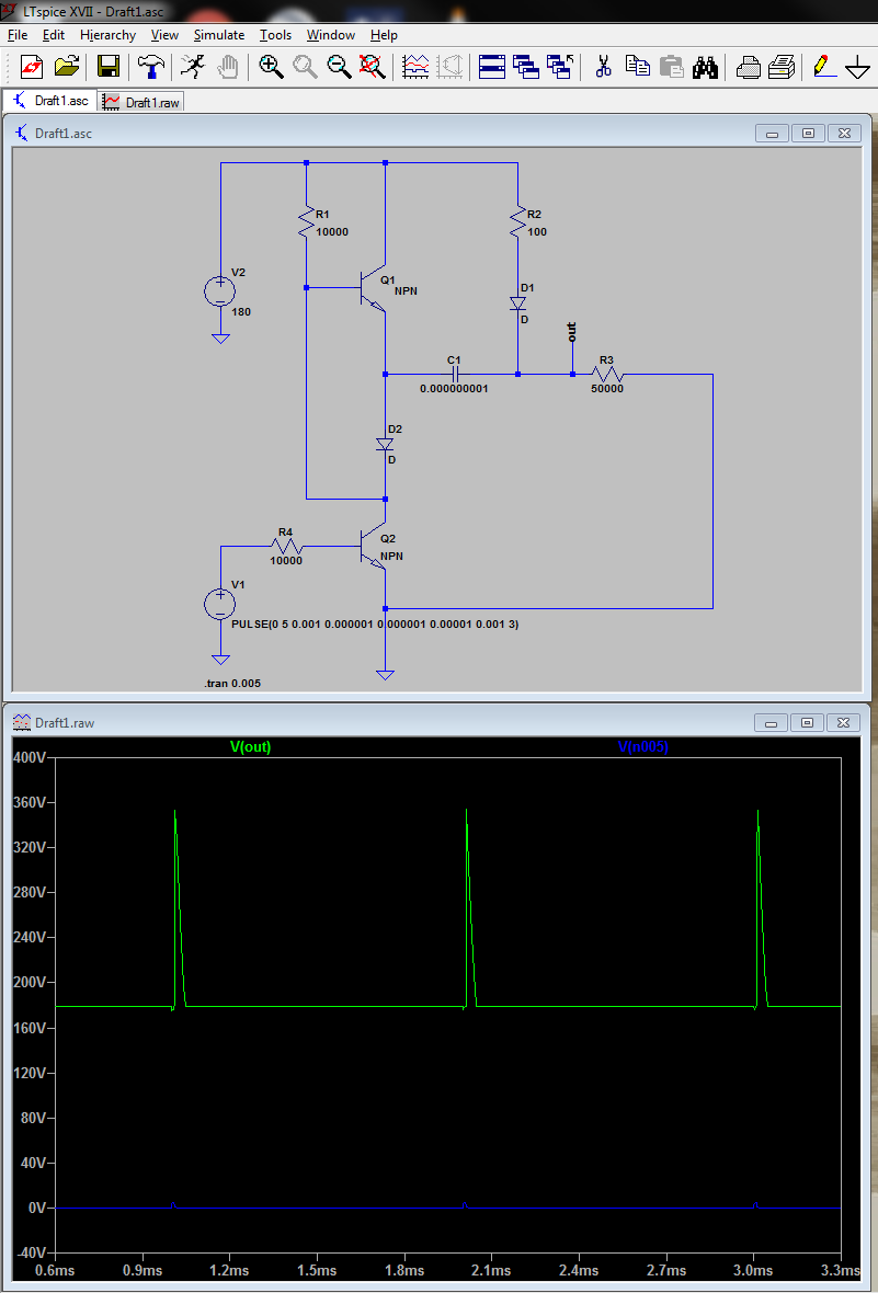
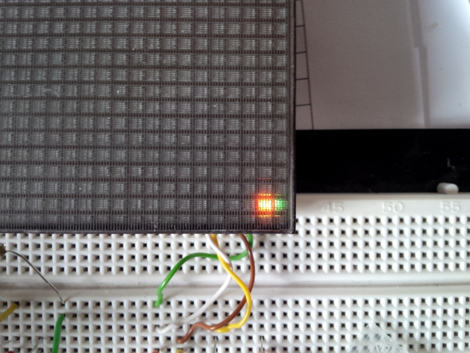
Reaching 360 Volts:

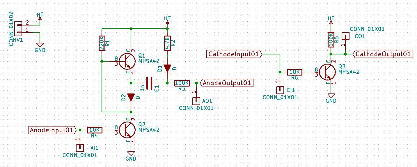
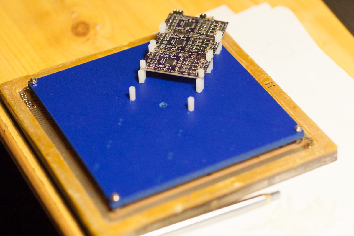
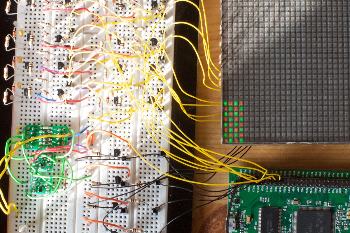
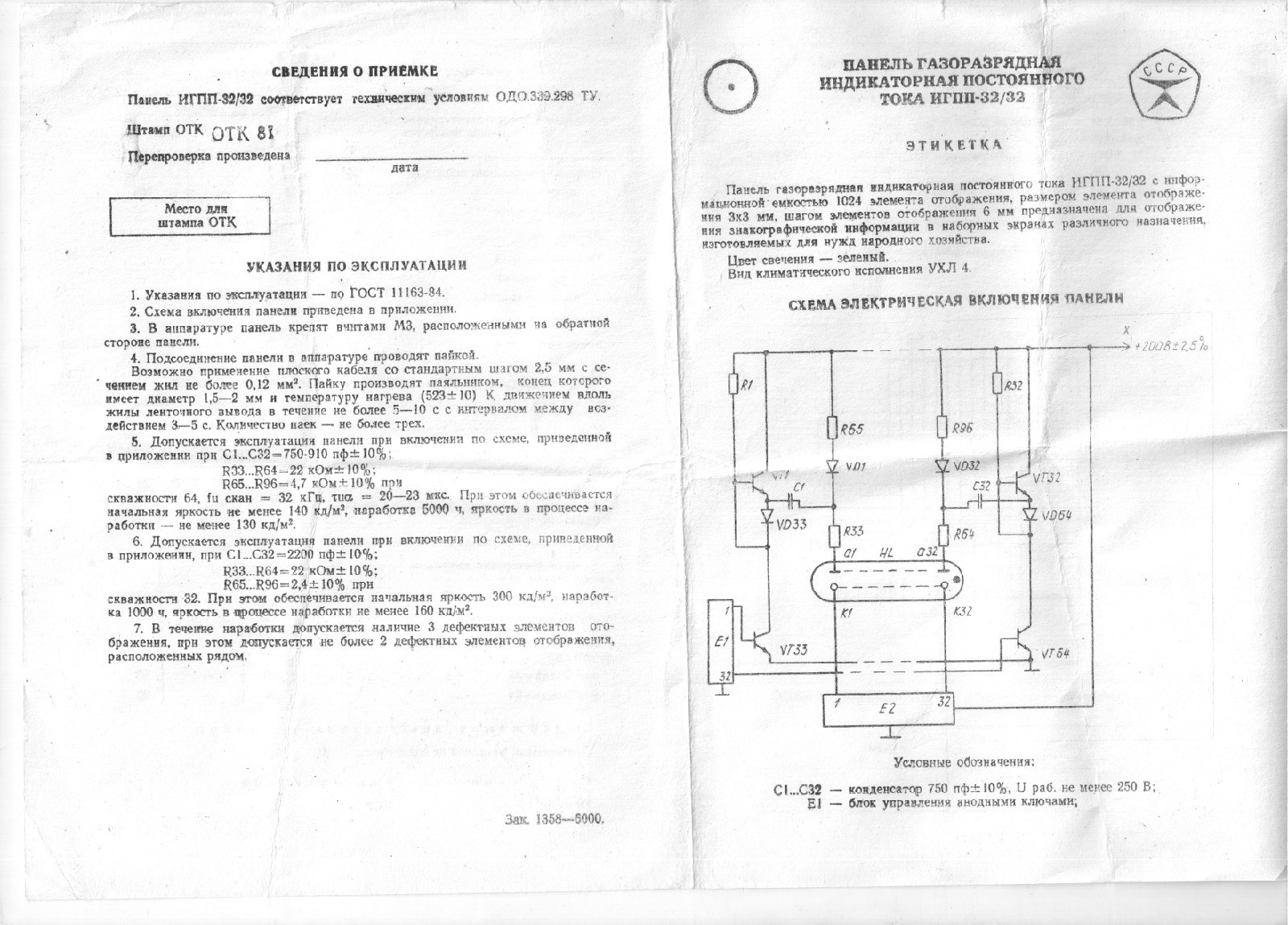
From schematics found on one of the screen type datasheet (see logs), the following circuit is used to multiply by 2 the voltage from a 180v nixie power-supply :

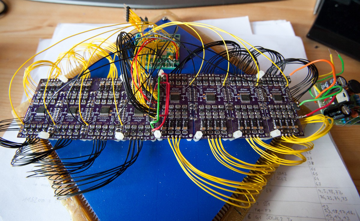
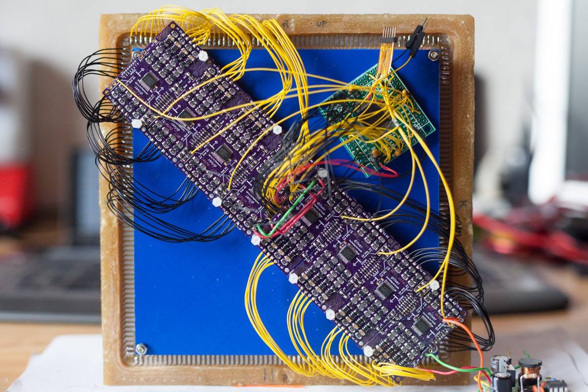
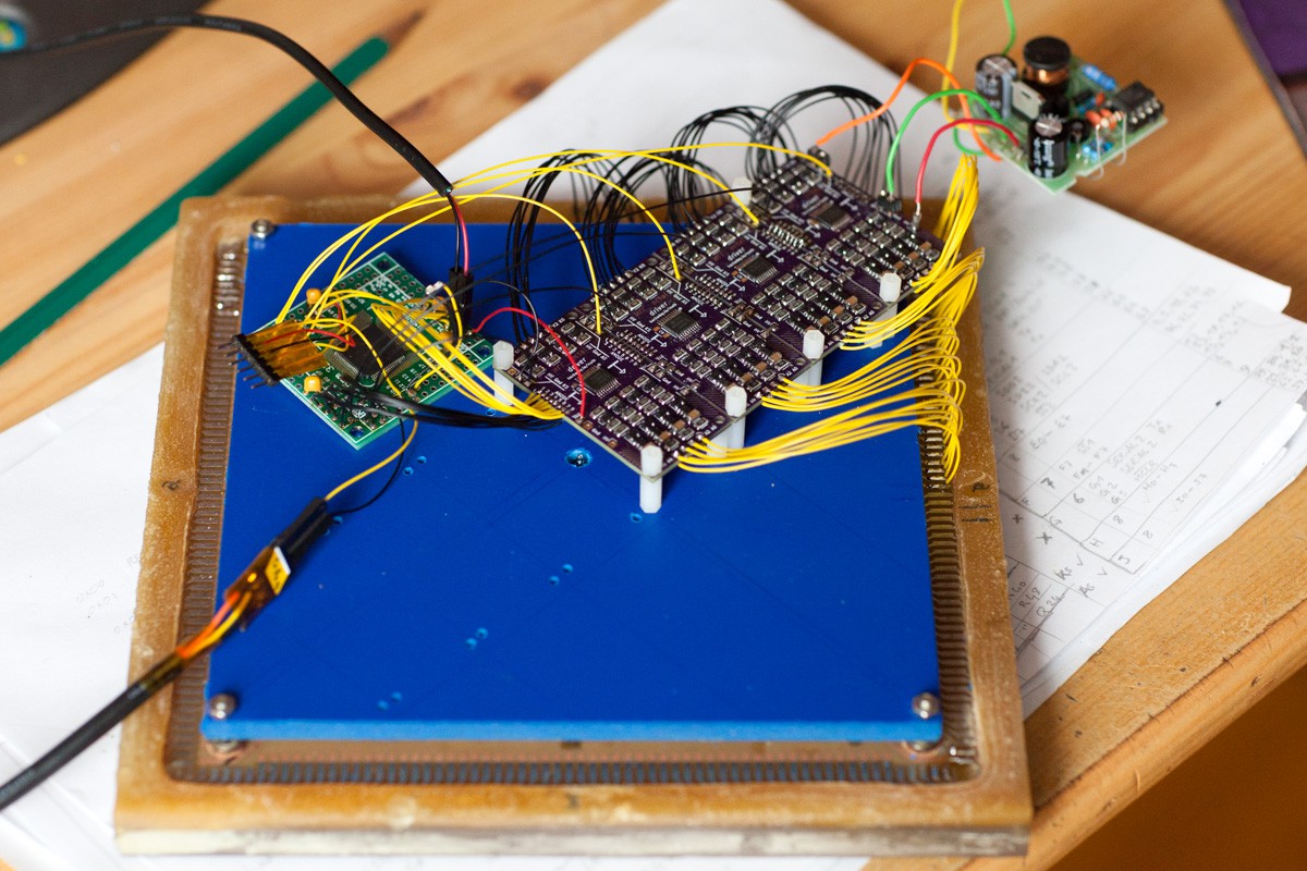
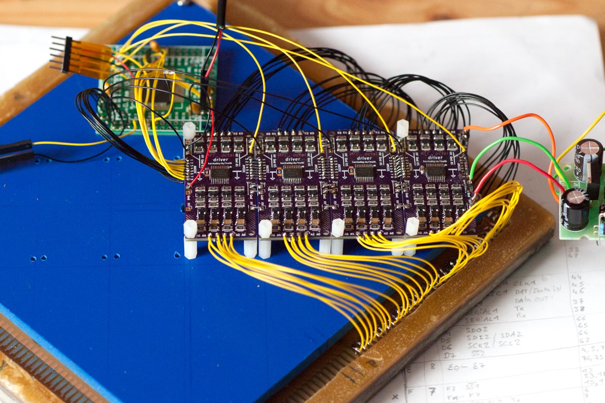
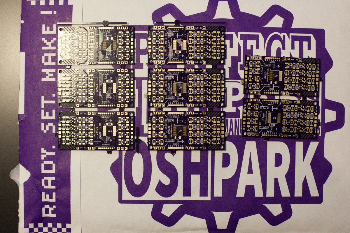
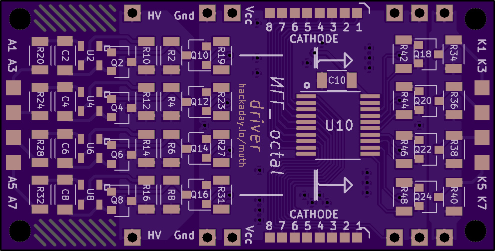
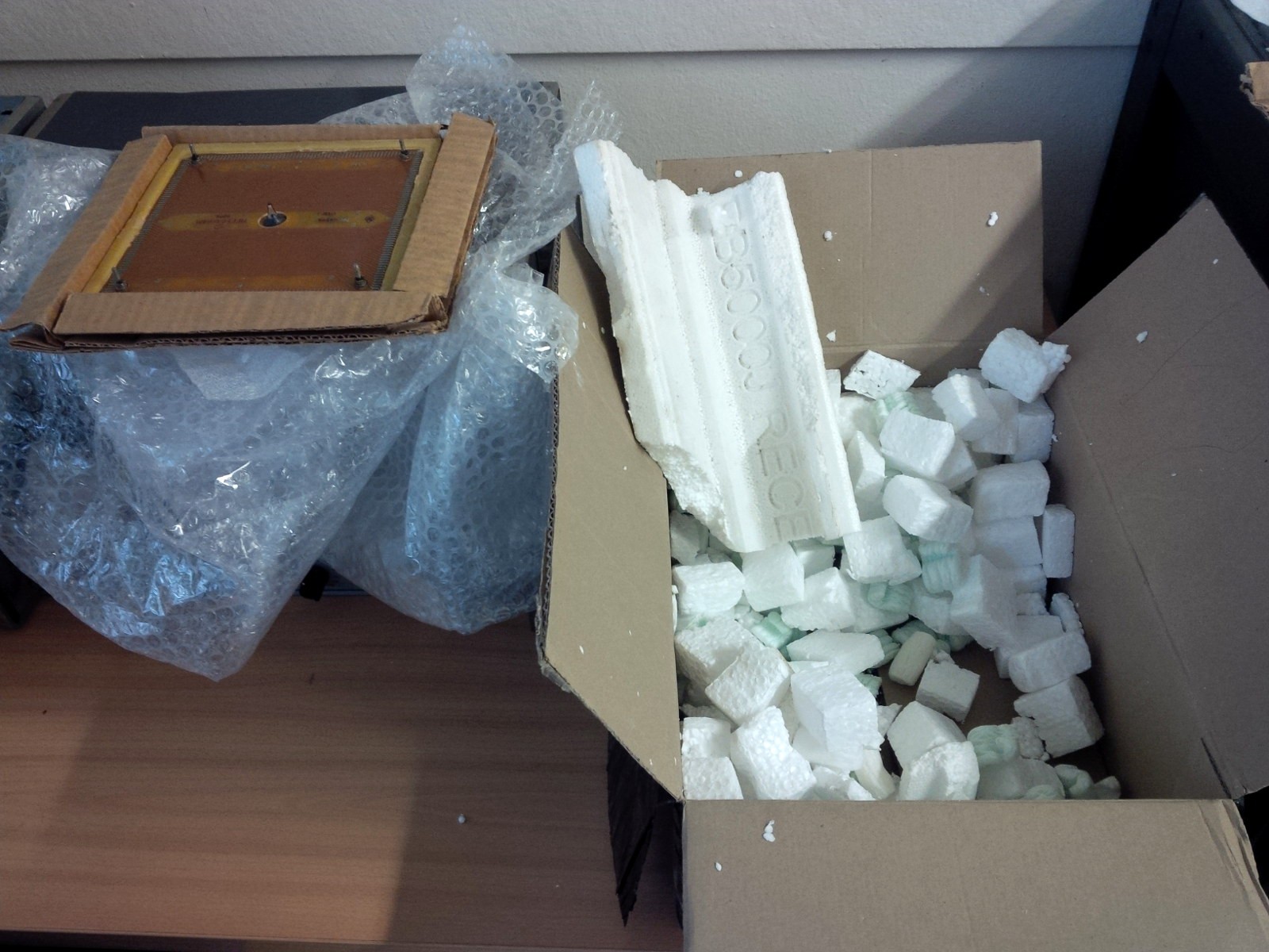
 Then packed 8 by 8 on a circuit bord:

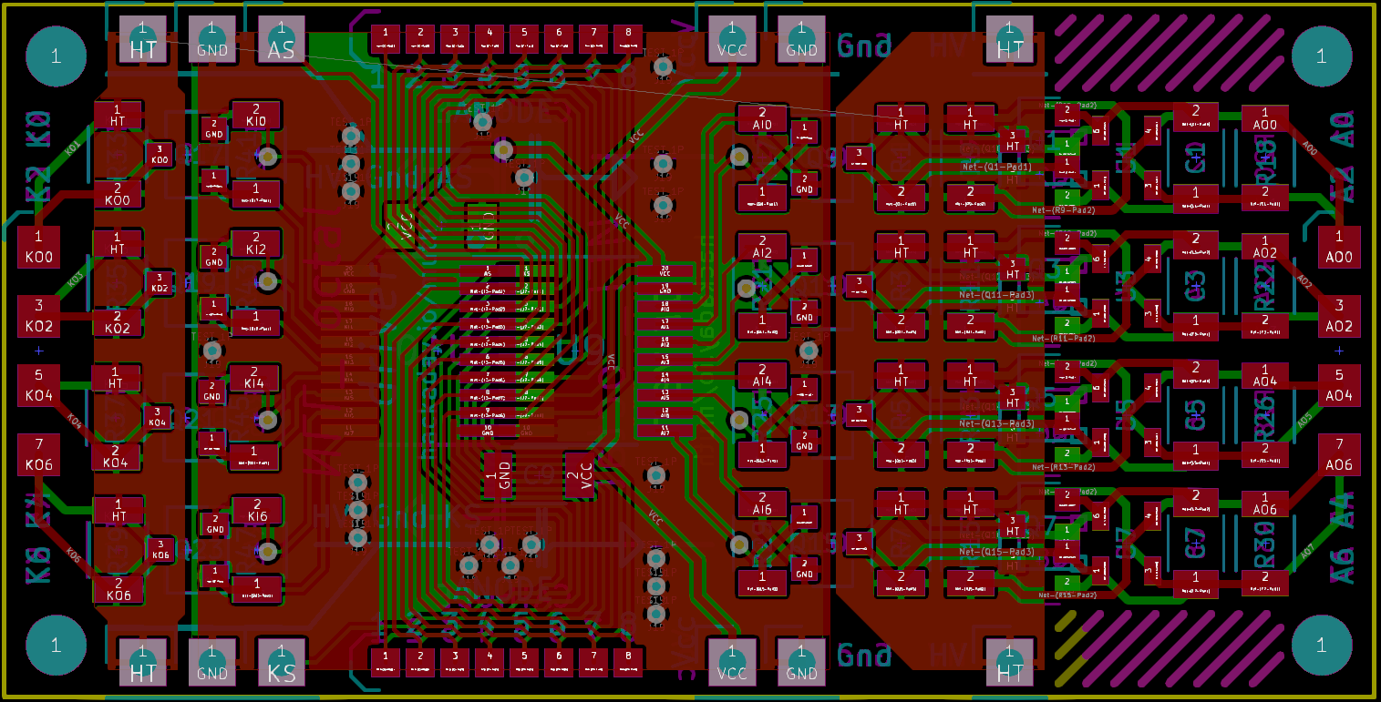
Available on OSHPark : https://oshpark.com/shared_projects/6yxoDPPP 

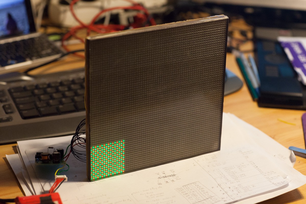
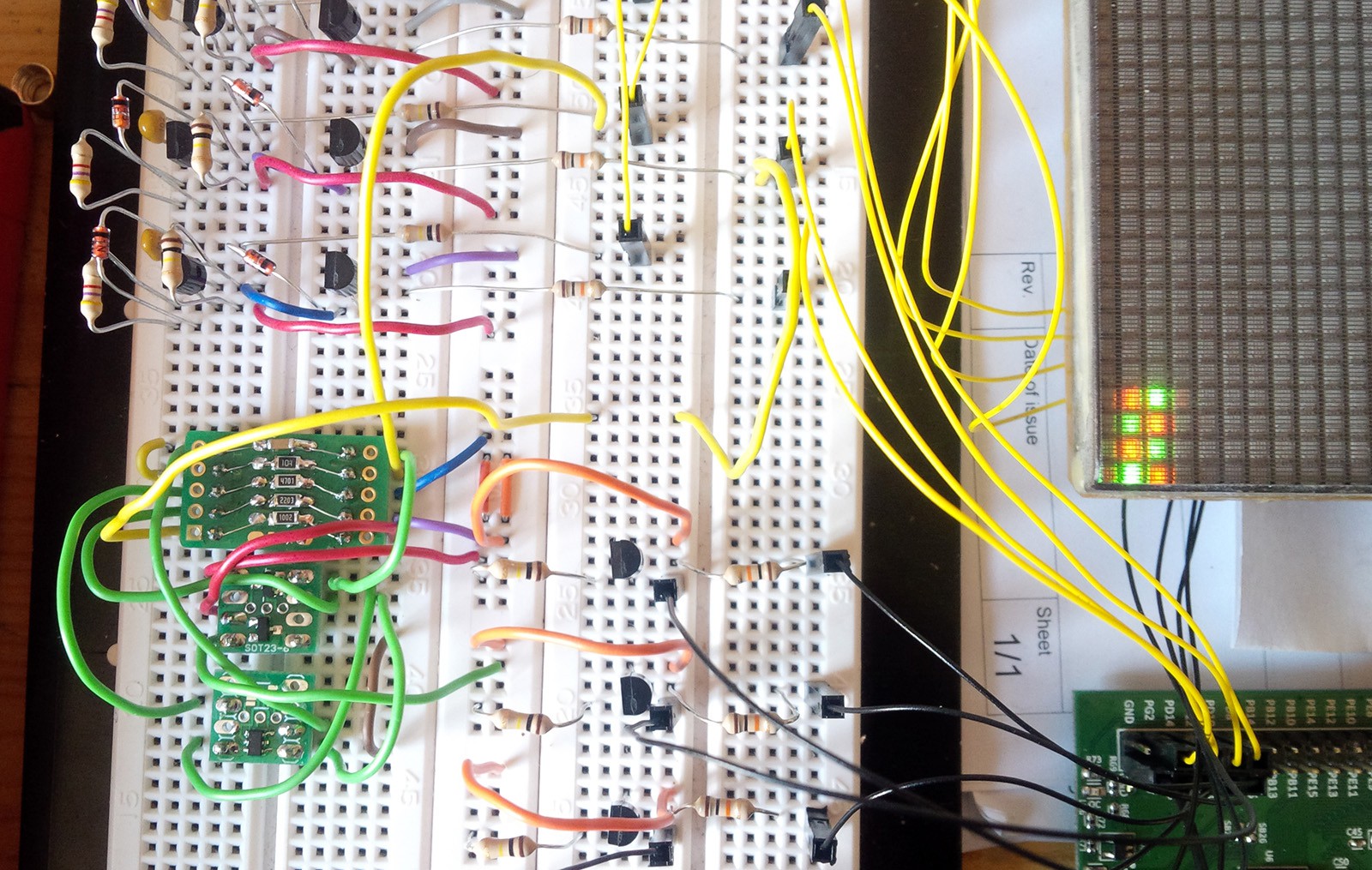
A first driving strategy:

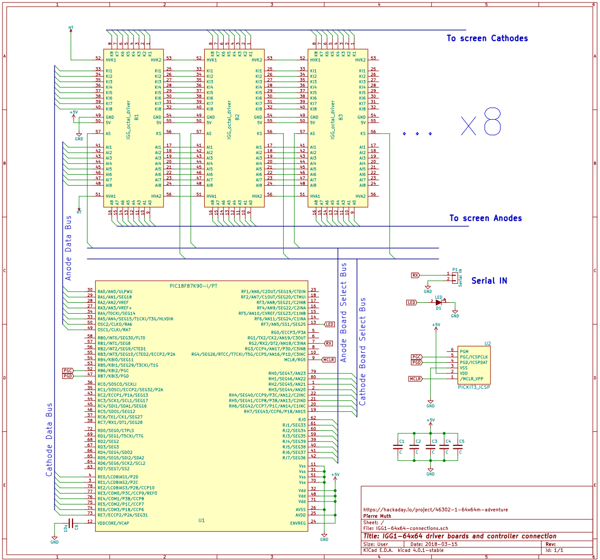
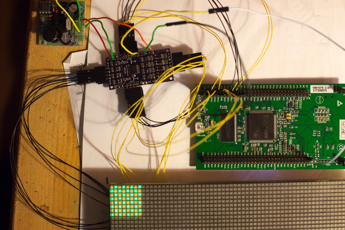
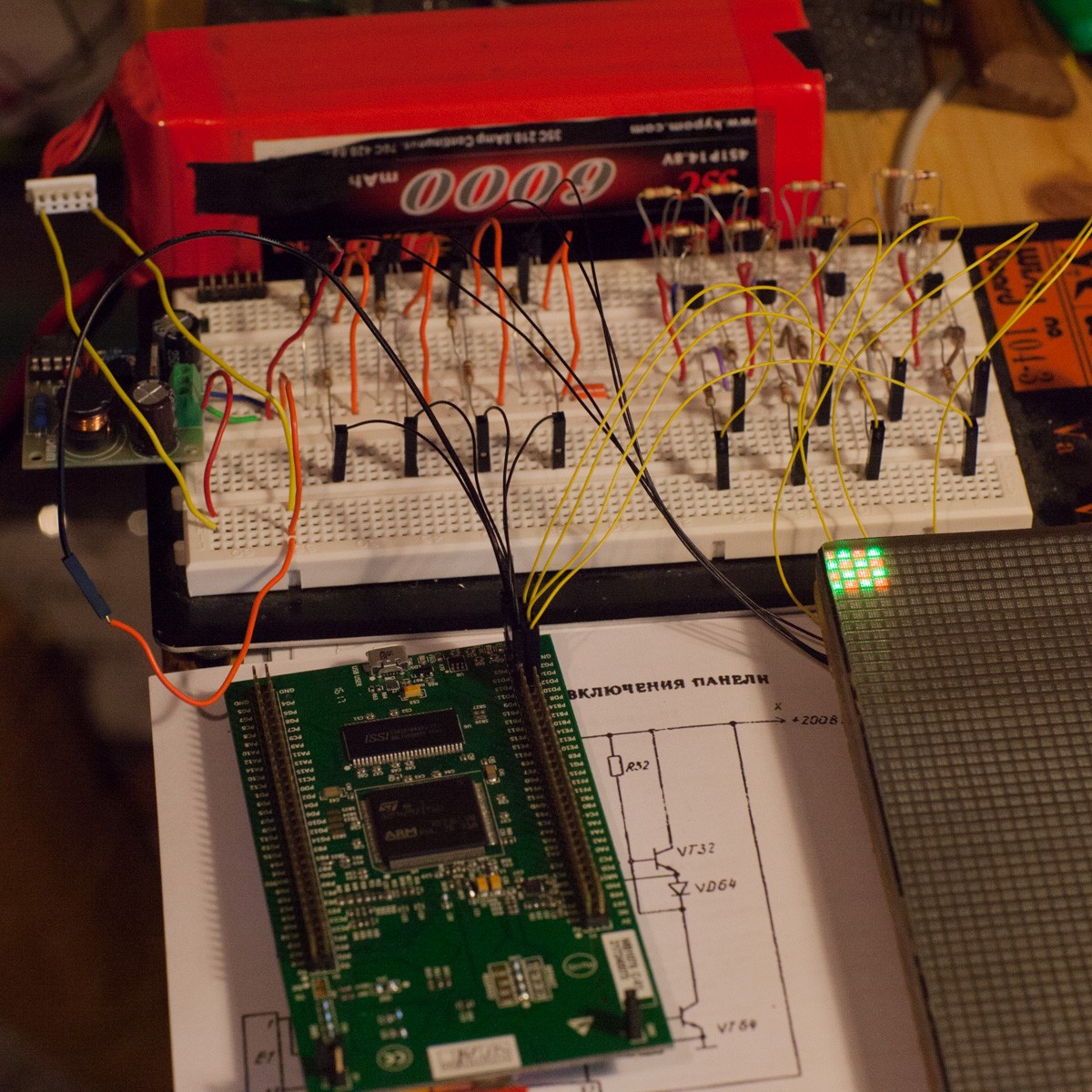
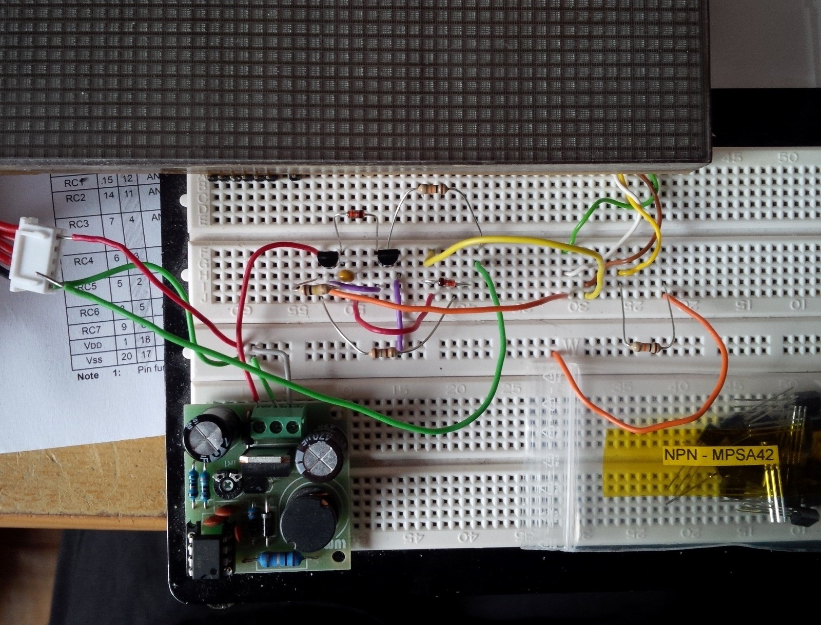
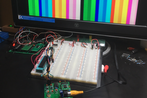
A large part of the scanning process can be achieved with logic components, such as counters and latches. However the high voltage boards are kept simple and are only enabled with a 8 bits tri-state buffer. They are controlled by a PIC18F87K90, and connected as the following:

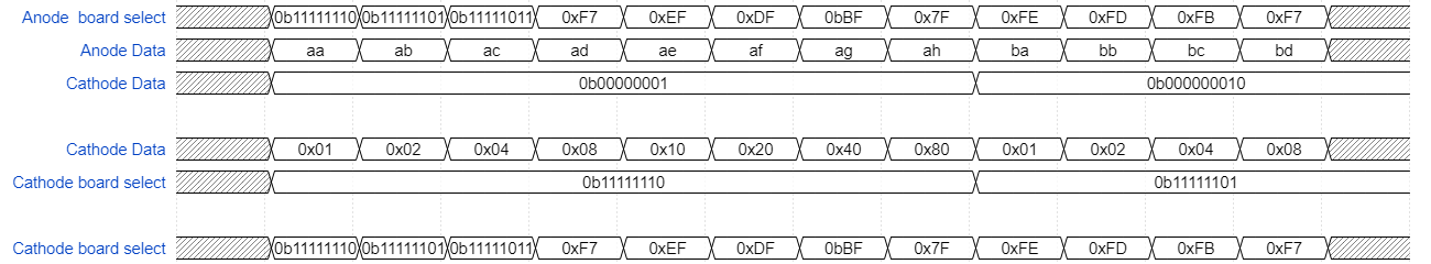
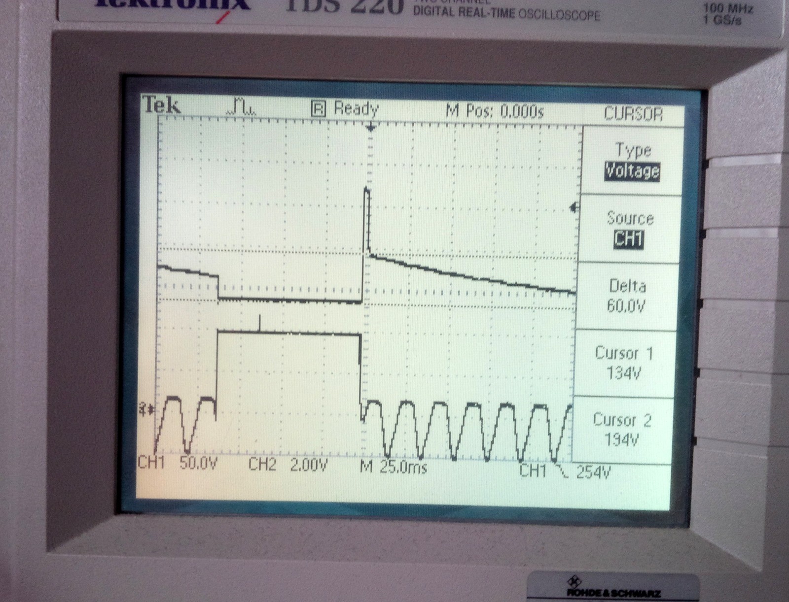
And the signals generated by the micro controller are:

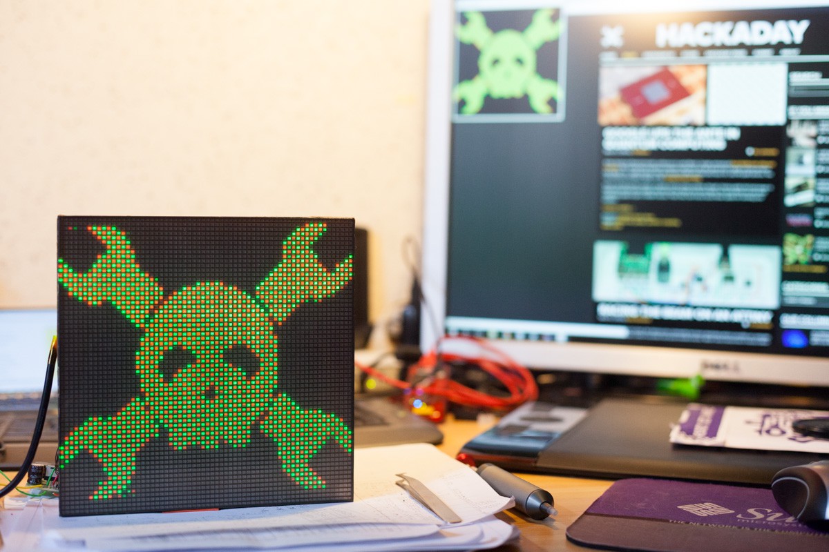
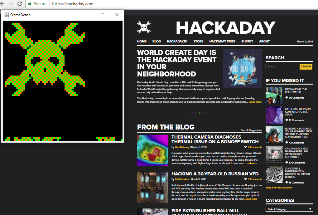
The micro controller receives data from the serial port to fill the 512 byte frame buffer. Sources (still in draft state) and schematics (kicad) are on github: https://github.com/pierre-muth/IGG_-64x64M

  • 16 × 74HC541 8 bit buffer 3 states
  • 64 × BAS21VD Discrete Semiconductors / Diode Arrays
  • 16 × Capacitor 100nF decoupling cap
  • 1 × PIC18F87K90 Microprocessors, Microcontrollers, DSPs / Microcontrollers (MCUs)
  • 8 × OSHPark board

View all 12 components

  • Fun with Pixel Dust

    Muth03/24/2018 at 11:10 0 comments

    I was quite amazed by the code demonstrated on a 64x64 led matrix by Adafruit : https://www.adafruit.com/product/3649 . So why not trying this on the IGG1 display?

    I have a MPU-9250 IMU and a raspberry-pi zero. However I need to adapt the code for this accelerometer, and send the data to the screen with the serial port. I'm more comfortable with Java than C or python, then I translate the code from https://github.com/adafruit/Adafruit_PixelDust in Java. 

    The code is on the same project github : https://github.com/pierre-muth/IGG_-64x64M/tree/master/java/src/pixeldust

  • 4096 pixels

    Muth03/09/2018 at 13:05 4 comments

    That was a job. After soldering 736 components and approximately 160 wires, the 30 years old display is alive.

    Some pictures of the back (please apologize the wire-mess) :

    And the front :

    And below the serial connection in action (115200 bauds, 5 frame per second, images taken around the mouse cursor of the computer) :

    As you can see there is still some artifacts, especially on the screen bottom. I still have to adjust the cathode bias resistor value.

    A funny fact is the screen is buzzing, adding a very old fashion touch to the retro style, in addition to remind you there is 360 volts in here. 

    Next step: a convenient and safer case !

  • Half way...

    Muth03/03/2018 at 15:11 0 comments

    It's a mix between what is yet accomplished and what remains to do...

    Half of the screen is cabled, it is yet at the level of the 32x32 kind of these displays.

    The PIC18F89K90 program seems functional, so I wrote a tiny Java program to send to it some images. It grabs a screenshot of the 64x64 pixels surrounding the mouse cursor, converts it to green-orange pixels and sends the data to the serial port every seconds.

    Despite some remaining artifacts, it start to be useful. I suspect the resistor that puts the cathodes to the bias voltage in order to inhibit it is a bit too high.

  • Gradatim Ferociter

    Muth03/02/2018 at 19:04 0 comments

    Step by step...

    I'm quite advanced now with the soldering of the boards. However I'd like to test the multiplexing of them.

    First I start to think how mount everything on the screen back :

    It fits very sharp on the diagonal.

    I decided to switch to a smaller micro controller, one of the PIC I already have and used for the LCD big_clock. With it I can easily scan the boards and pins plus enable serial interface. It have plenty enough of RAM as well.

    Then I cabled 2 boards for 16x16 pixels drive :

    And well, it start to be more and more likely this strategy could work !

    Next step: more cabling ;)

  • Test Drive

    Muth02/20/2018 at 23:03 0 comments

    The perfect OSHPark PCBs arrived today, fedex instead of usps this time. 

    So it's time to test ! Nope, first warm this soldering iron... There are 92 components per board... However it is always a pleasure to work on these purple boards, they are really accurate and well made. 

    I noticed I made small mistakes on the numbering, such as labeling the inputs from 1 to 8, but the outputs from 0 to 7...

    But... it's working :)

    The voltage source is 180v and correctly multiplied by two for the anodes. I still have some artifacts during animation: some pixels take some time to switch off. That's why I let separated on the circuit the voltage source for the anodes and the bias voltage for the cathodes. Maybe some better parameters can be found.

    The next steps now are the following. Solder 7 more boards. Make a quick micro-controller program to scan correctly the 32 inputs (8 anodes data, 8 anode board select, 8 cathodes select and 8 cathode board select). Mount everything together. Send data from a computer or raspberry pi to the uC with the serial port.

    The adventure just begin :p 

  • More tests and a PCB

    Muth02/09/2018 at 18:54 2 comments

    Usually dot matrix displays use shift register, demux, counters to scan the column while driving the rows. In the most multiplexed option, only 2/3 timing and one data lines are needed. A frame sync, a column clock and a pixel clock. Then the pixel data is synced one by one. Resulting a rather high frequency toggling on the data line.

    I would like to try to send the data 8 by 8, so for a 100Hz refresh rate, instead of 409.6KHz, it gives 51.2KHz. Doing so will reduce the logic components needed as well. 

    Before going further, I would like to test driving the anodes 8 by 8. The circuit to generate the 360V pulse need to charge a small capacitor, and my little power supply had to handle the current peak to charge them 8 by 8.

    So I cabled 8 anode drivers on the breadboard but had to use the FMMTA42 SMD transistor for 4 cathodes as I didn't have enough MPSA42 transistors. I tried the timing parameters as if the all screen is driven. To summaries, the cathodes are switched one after the other at a 156us rate (100Hz * 64), then wait 10ms as if the screen is at 100Hz. And the 8 anodes are charged during a 8th of that time as there will be 8 block of 8 pixel to drive per cathode.

    I think it needs some adjustments, mostly because I forgot here to introduce a small pause between the cathode switch. It  results that some pixels are flipped with a small delay. However, it seems to be promising for more pixel driving.

    The brightness could be improved by increasing the refresh rate, but I faced unstable pixel ignition. It is maybe due to a too short time to charge the capacitors.

    Besides, the brightness is correct, below is in a room with the direct sun luminosity (3:00pm):

    And then the same with two light bulb:

    I spent few hours to draw a small PCB to drive 8 anodes and 8 cathodes. I've just put a logic buffer in order to have a 'chip select' line. That way I can quickly drive a full screen with 32 GPIO. It's a lot but doable with a microcontroller. The aim is to check rather easily if this driving strategy is valid before continuing. If it's working I can keep the 8x8 driver PCB and think about a more efficient logic.

    The buffers are 74HC541, transistors are FMMTA42, diodes are BAS21VD. And the Kicad source is here : https://github.com/pierre-muth/IGG_-64x64M/blob/master/IGG1_OctoDriver.zip

    And I've ordered them on OSHPark : https://oshpark.com/shared_projects/6yxoDPPP

    Now I have to be patient !

  • Next step: SMD

    Muth02/03/2018 at 10:50 0 comments

    In the view of making a PCB to hold the 64 anode drivers plus the 64 cathode ones, it is time to test some SMD components in order to make it as compact as possible.

    For the transistor, there is apparently a equivalent from Diodes inc, the FMMTA42, 0.03€ in 250 quantity. The high voltage diode can be a bit expensive in smd format. However NXP has the BAS21VD, which is 3 diodes in a SOT package, 0.06€ in quantity of 100.

    I would like to take some margin with the passive components regarding the max voltage rate. It appears resistor and capacitors are more easy to find in 1206 format than 0805 for a >200v grade.

    Fortunately I have convenient adapter board to make some test on a breadboard to ensure the components works:

     Here the second anode is driven with the SMD components while the others with the previous ones. No difference is visible, so maybe it's time to start KiCad. And start to think about some shift registers and demux to drive these circuits without the need of 128 GPIO!

  • A second read and perseverance

    Muth02/02/2018 at 16:07 0 comments

    Fortunately I know a Russian colleague that helped me to understand a bit further the panels datasheet.

    The two important parameters I missed was the anode load, which appear to be 91KΩ, and the pulse length that should be 12µs. Additionally with a frequency of 500 to 1000Hz and a duty cycle of 64.

    On google, or even Ebay, you may find these kind of appealing images :

    And if you insist gently on google, you will eventually find this Russian forum. Here google translate is your good friend. I suppose it is the origin of this image, http://radiokot.ru/forum/viewtopic.php?p=461563#p461563, done by SLvik :

    A bit more roaming here and I found this image:

    http://www.radiokot.ru/forum/viewtopic.php?p=2547127&sid=804d6efe3e14ad54b9ec8e56b7a81830#p2547127

    So my wild guess from the youtube video was not so wrong. So lets draw the schematics with better values:

    And cable a 4x4 matrix to test everything:

    And there were light !

    As you can see, I use a quick and dirty program on an overkill STM32 (F429!) with mbed to scan the cathodes and put synchronously some pattern on the anodes:

  • A first thought

    Muth02/02/2018 at 15:15 0 comments

    Even before receiving the panel from ebay, I sought information on internet about how to use these displays. There is of course a short datasheet supplied with it, but no clear schematics for a driving circuit. The datasheet is shown in the dittohead's page.

    I found someone managed to display a space invader on the 32x32 version and made a video of it :

    I tried to extract a schematics from the video, but the type of the transistors and some values of resistor and capacitors are unreadable.

    I deduced the following circuit, where the 360v needed to ignite the elements are produced by switching in serial with a 180v source a capacitor charged at the same 180v.

    So I started to reproduce on a breadboard the circuit for one anode, and put one cathode to the ground. I used a 'nixie' high voltage power supply (by lumos.sk, nicely done by the way), some stupid guesses for the resistor and capacitor values, small diodes, and MPSA42 transistors.

    I got the 360v short pulse when I put the transistor Q2 base to 5v.

    And it lights up.

    But a bit too bright, in the sens of I'm damaging the elements. It is clear too much current is drawn, or the pulse is too long. After few minutes of running the pixel got dark, event not powered, the burn is visible.

View all 9 project logs

Enjoy this project?

Share

Discussions

Russell Borogove wrote 02/10/2018 at 19:16 point

I just picked up one of these displays and hope to ride on your research coattails. :) I got boards for an audio project from OSHPark recently and was really happy with them!

  Are you sure? yes | no

Wenting Zhang wrote 02/06/2018 at 22:20 point

Nice project! I also have one of these screens, but haven't tried driving them yet.

  Are you sure? yes | no

shapr wrote 02/03/2018 at 18:21 point

Have you tried running the panel at lower voltages? I found the microchip HV507 shift register that takes 5V serial and outputs 64 bits of 300V parallel.

I have one of the two color panels in hand, and have ordered three of the RGB panels, so I'd like to know more!

  Are you sure? yes | no

Muth wrote 02/03/2018 at 19:19 point

Hi Shapr,

I had the hope at first to use these high voltage shift registers, they are commonly used to drive EL or VFD displays. And I agree, it would be so convenient ! (You can find a bucket of them on glass damaged electroluminescent diplays)

Unfortunately, from what I've measured so far, the voltage spike needed to ignite the pixels has to be greater than 300v. I have a stable display with the bias voltage at 180v, thus 360v spike. I've just tried to lower it and it start to be unstable at 160v (320v peak) and stop working at 150v (300v peak). By unstable I mean some pixels are not ignited, some are.

  Are you sure? yes | no

Similar Projects

Does this project spark your interest?

Become a member to follow this project and never miss any updates