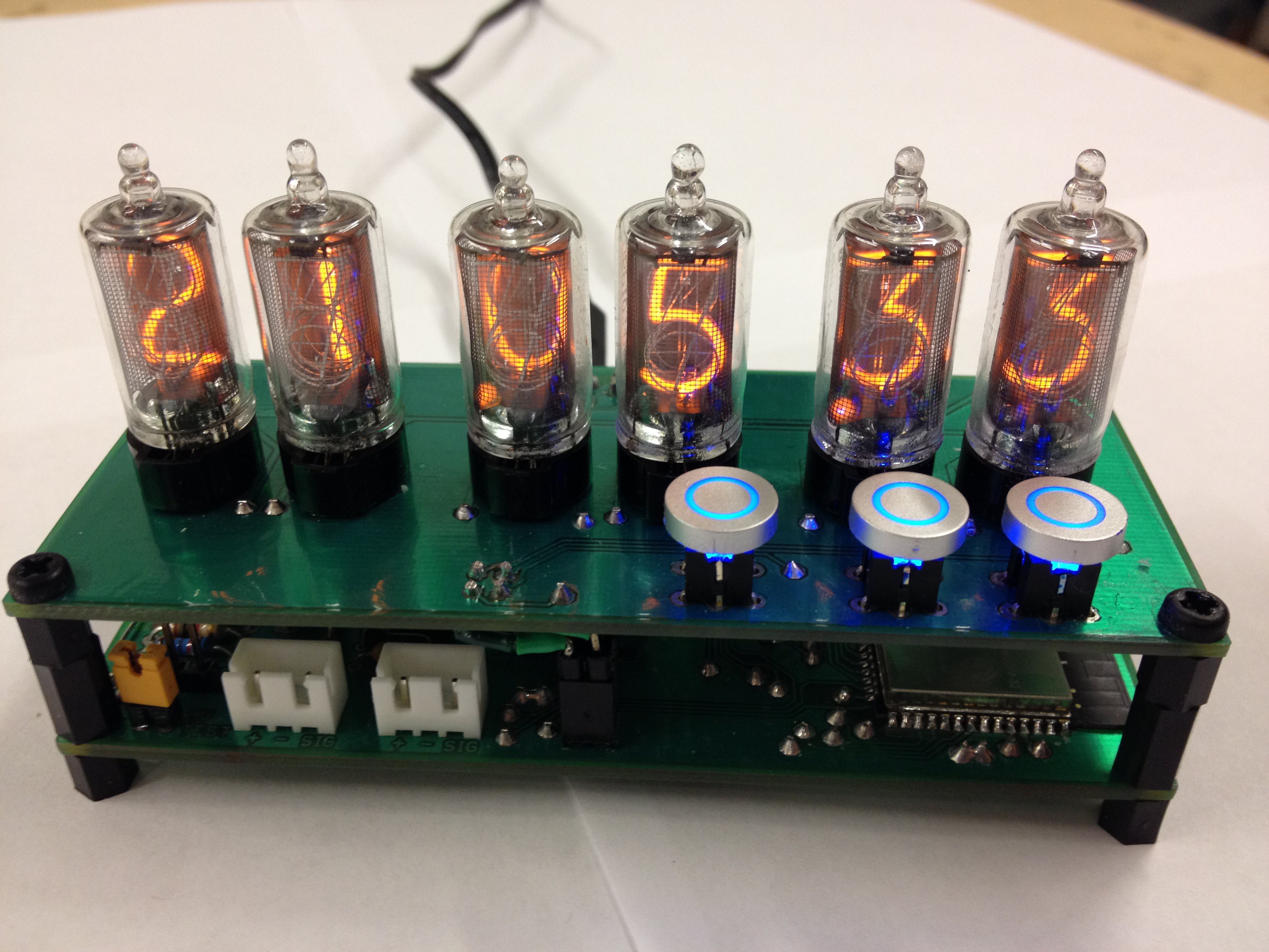
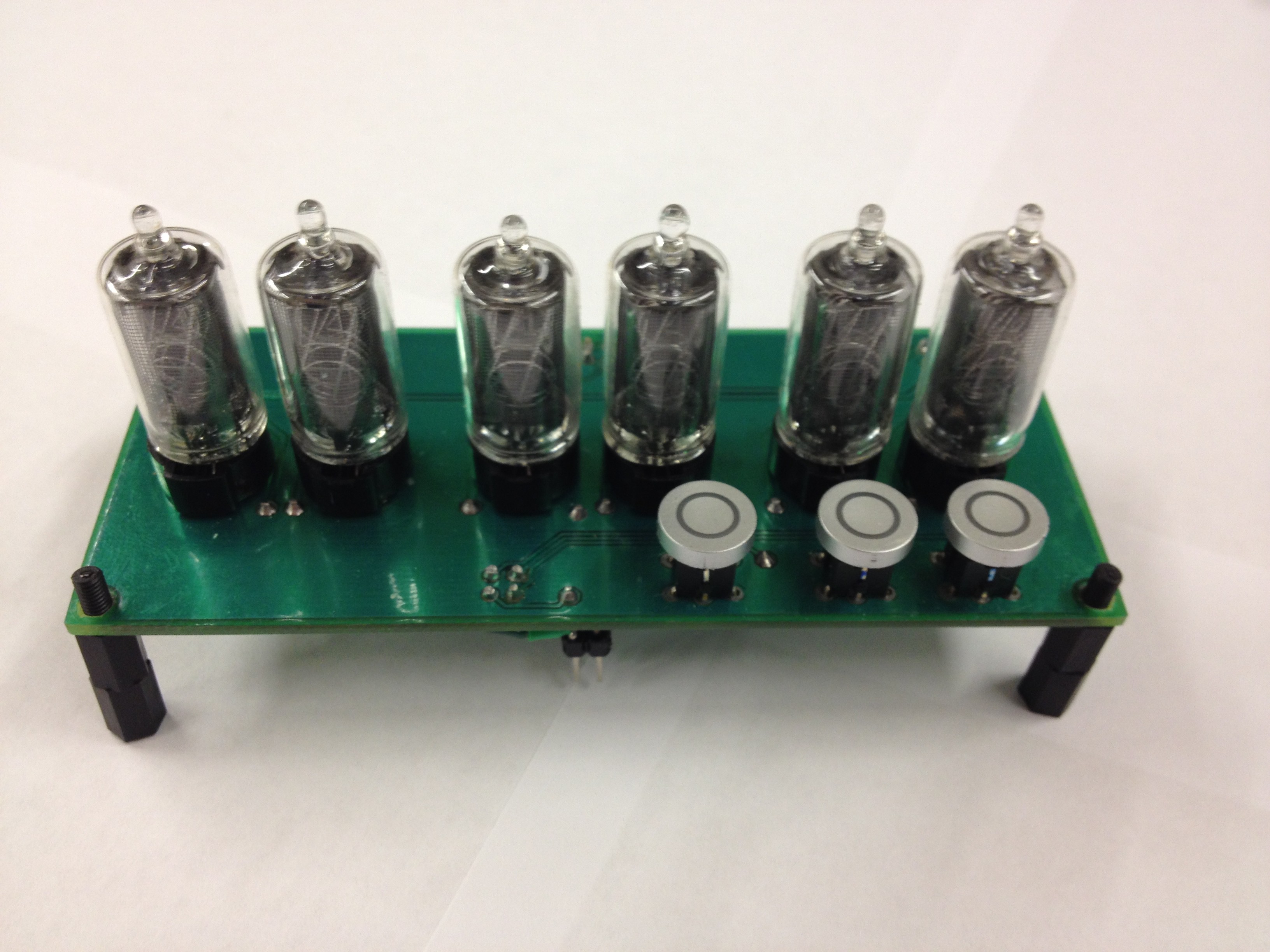
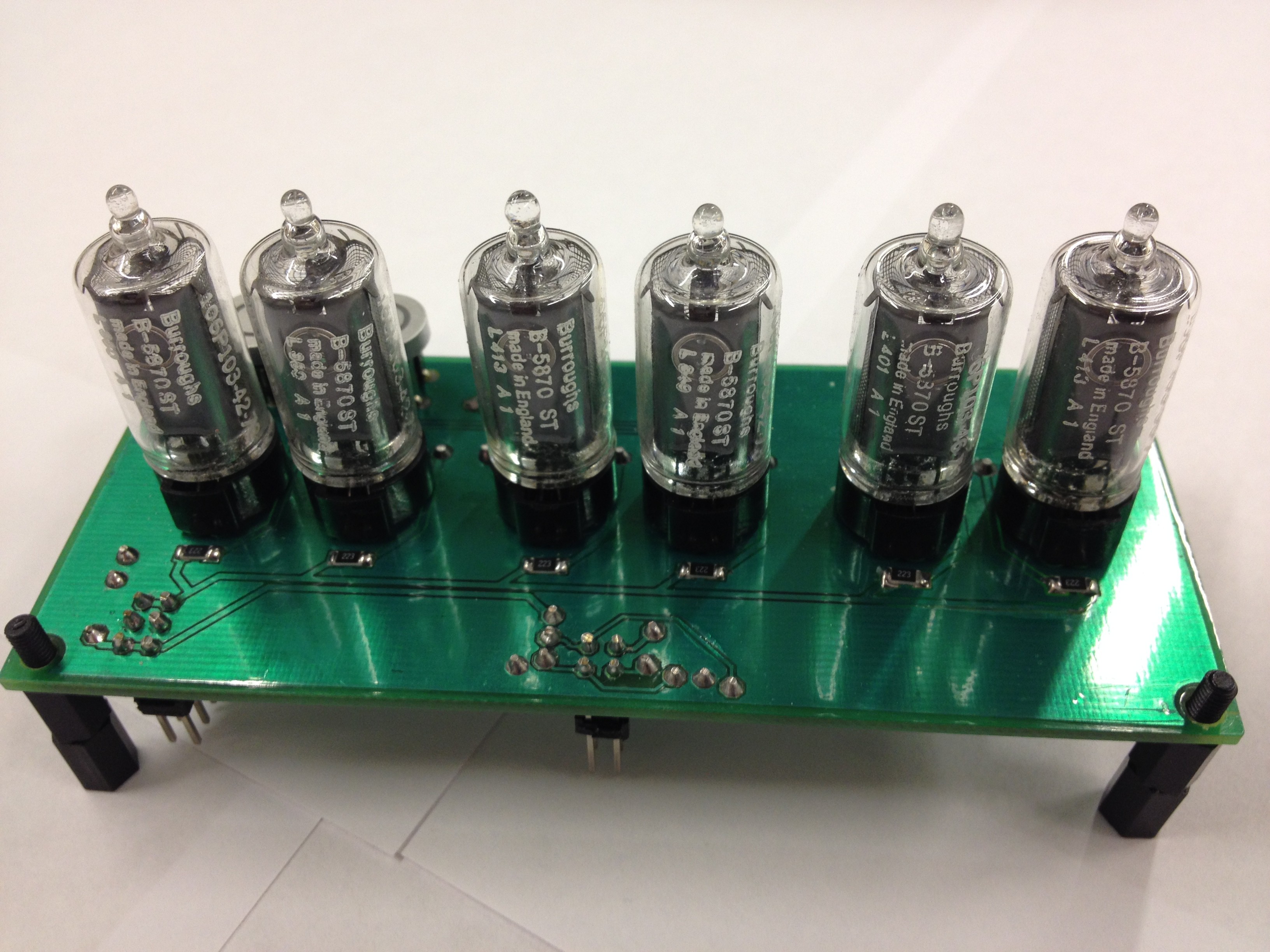
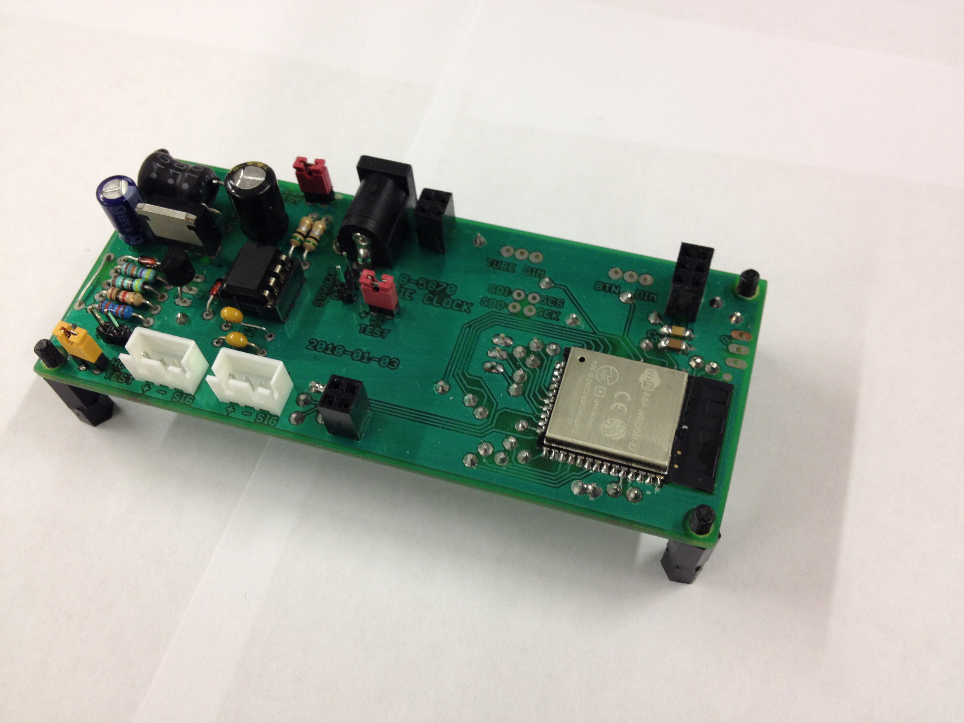
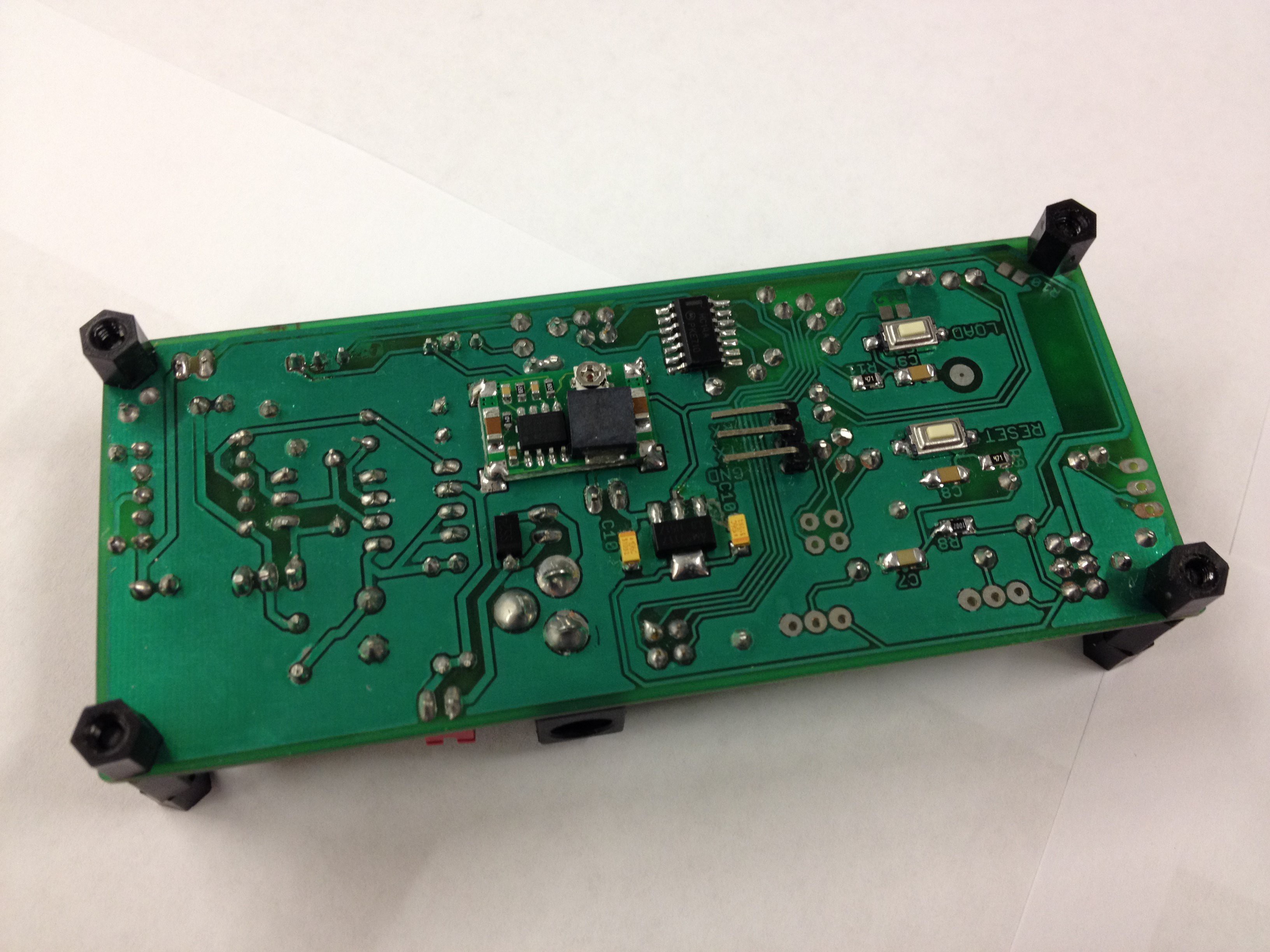
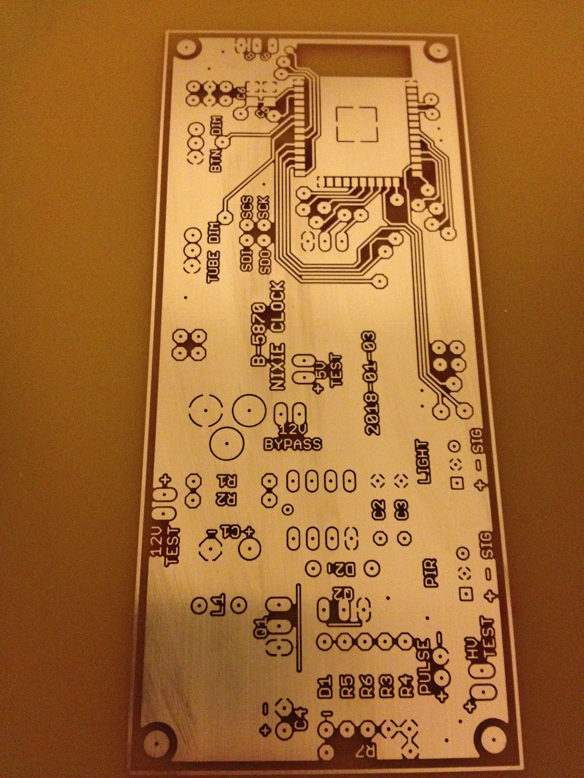
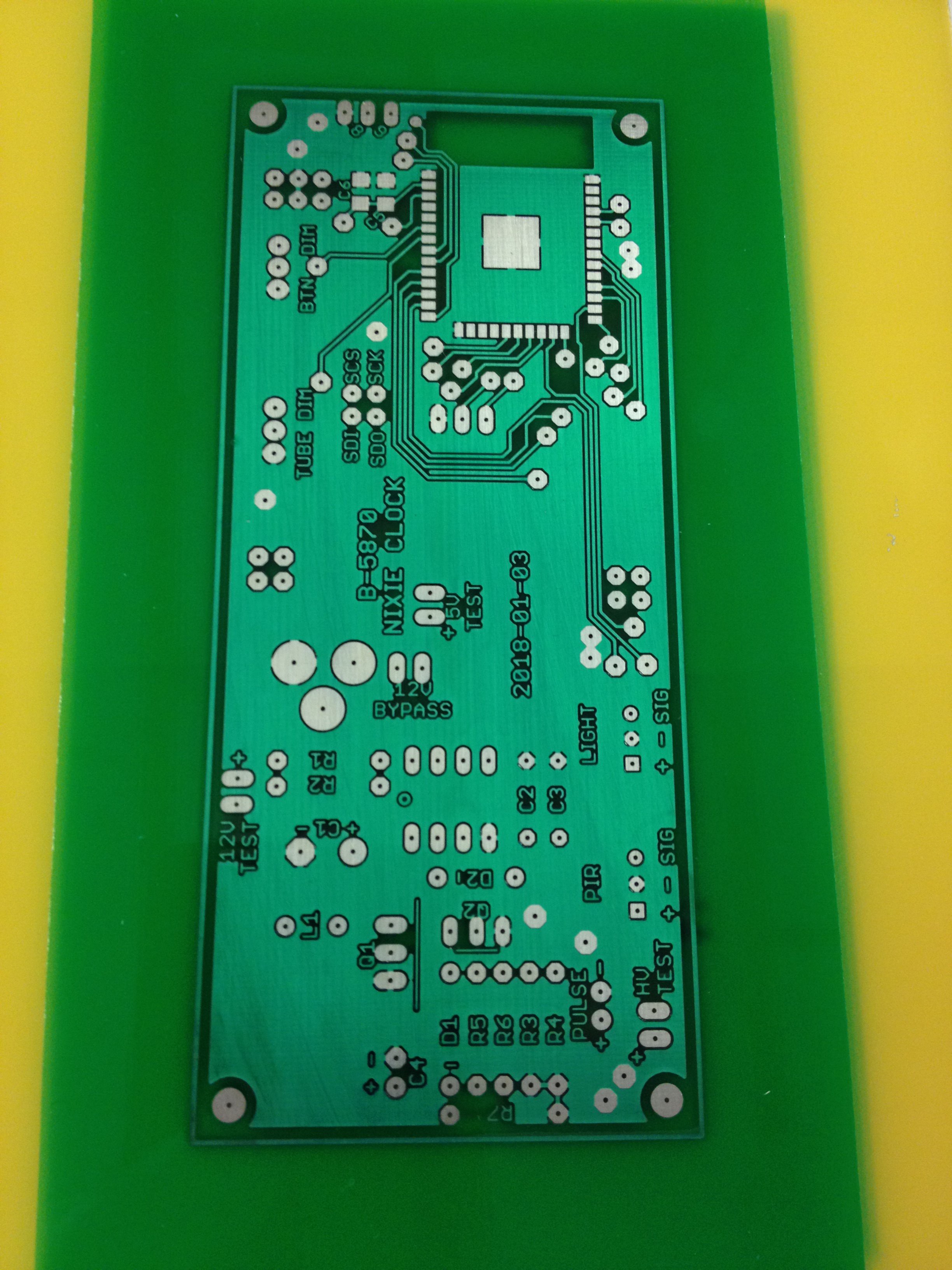
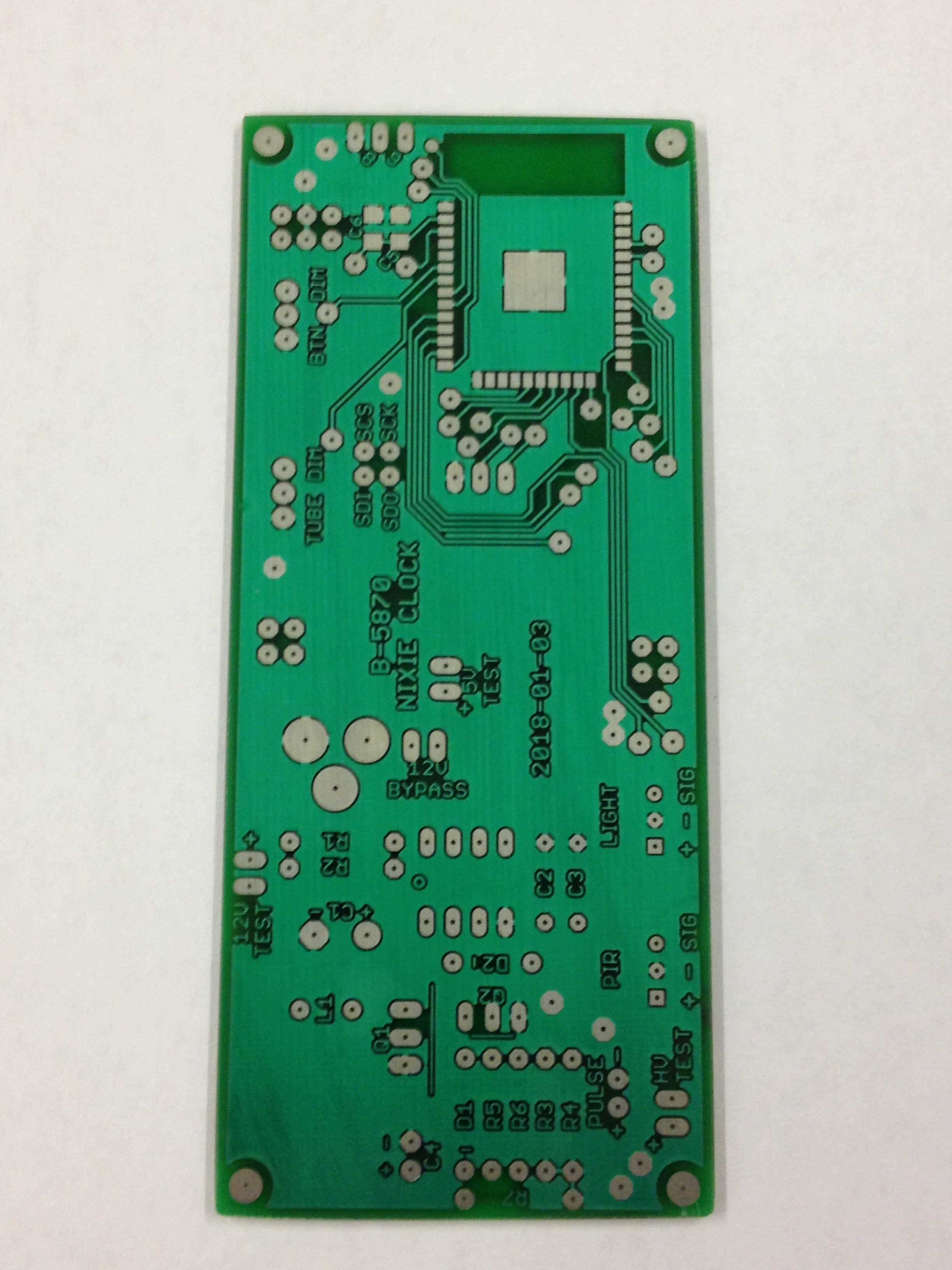
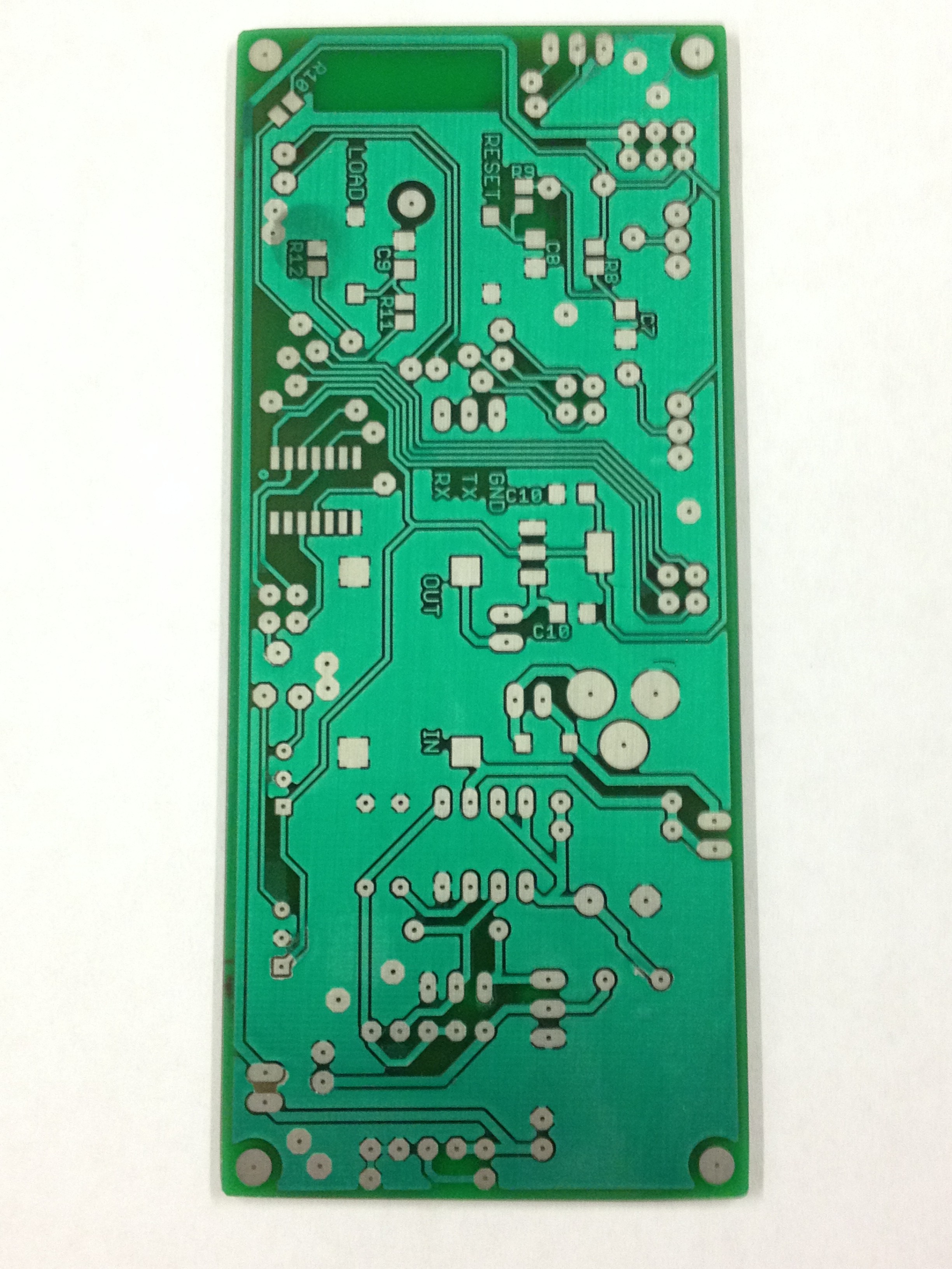
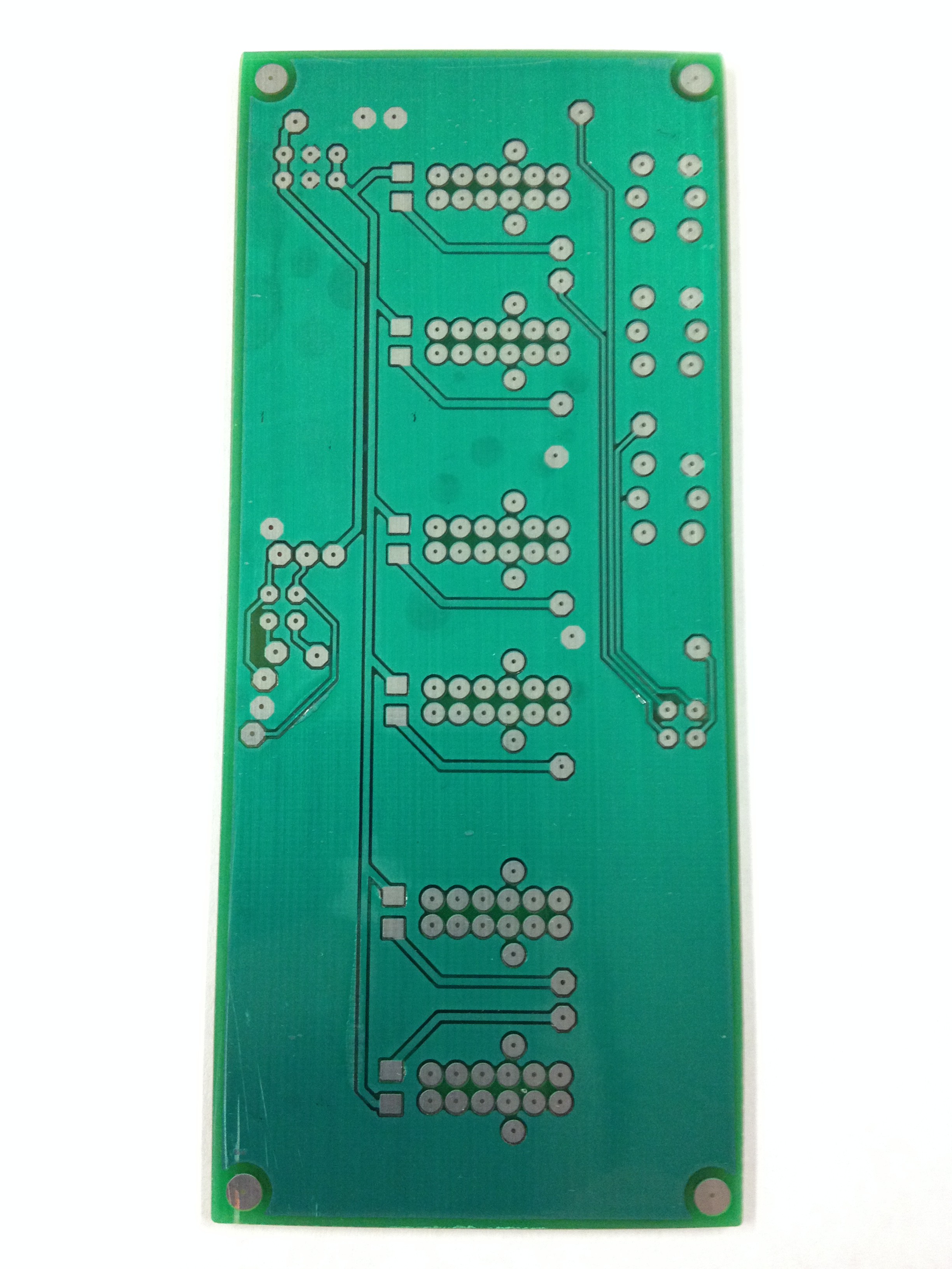
The clock comprises two circuit boards. There's a board that holds the tubes and buttons. There's another board that has the power supply and other various components. The high voltage power supply I copied from a kit I got from ebay. I simply copied the circuit into my schematic and used the components from the kit on the PCB I made.
My first clocks used the common Russian driver chips and I used multiplexing in order to achieve dimming of the tubes.
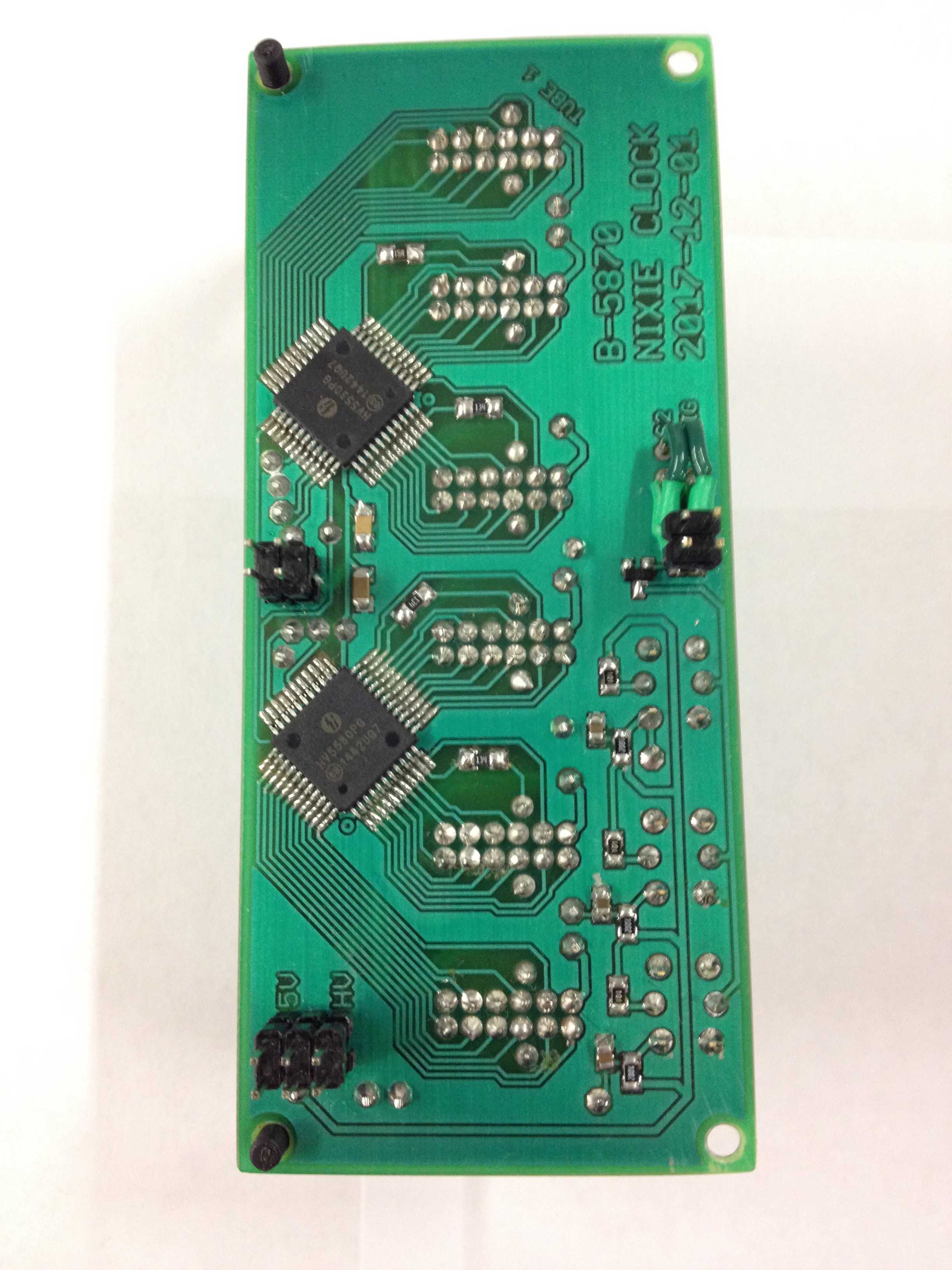
This time I wanted to use some HV5530 chips that I had read about from other people using them for clocks. They work really well and are a LOT simpler to integrate and dimming is achieved by the ability for the chip(s) to blank. So it's a straight forward matter to just vary the tubes on and off cycles via this blanking feature.
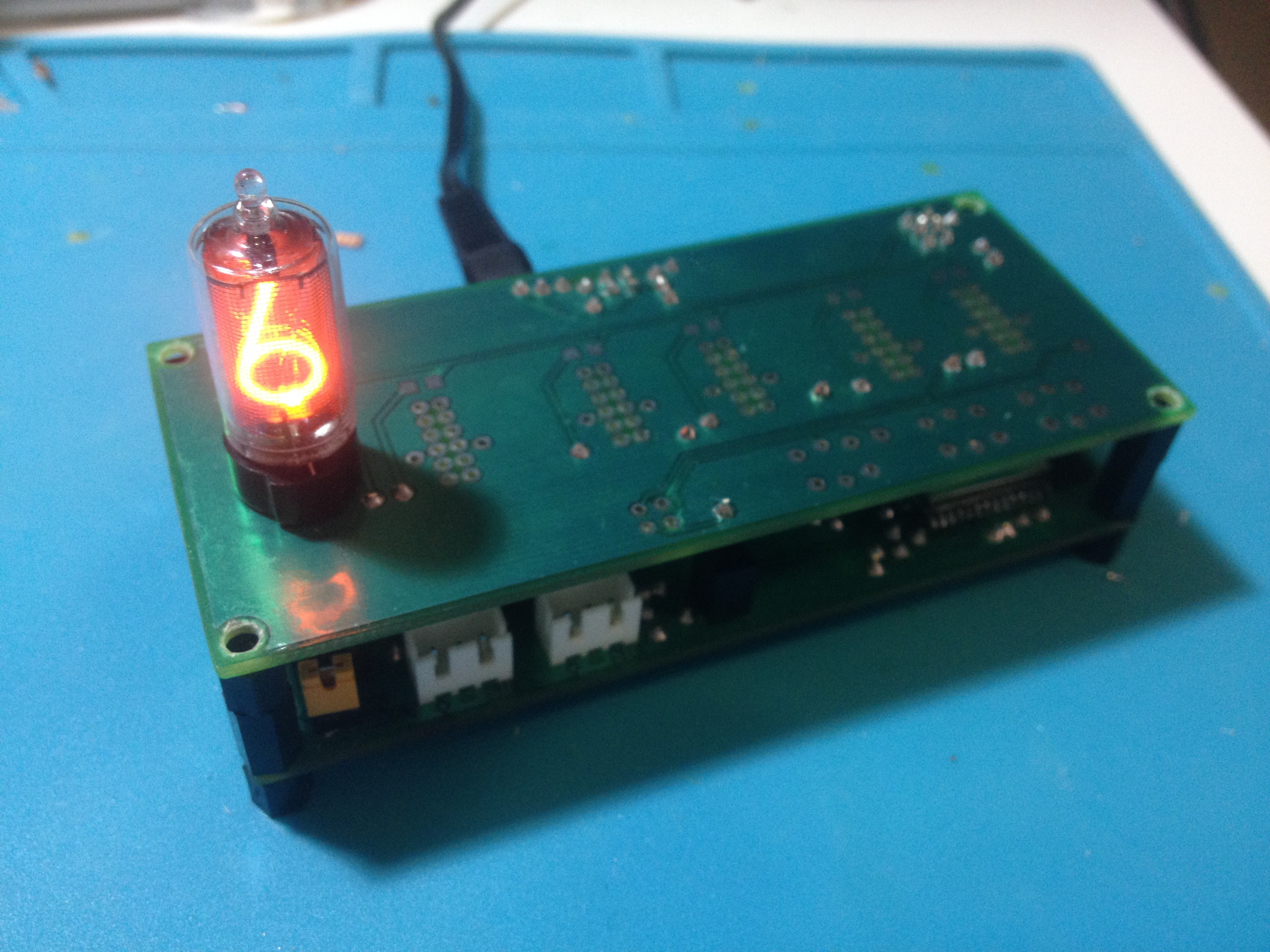
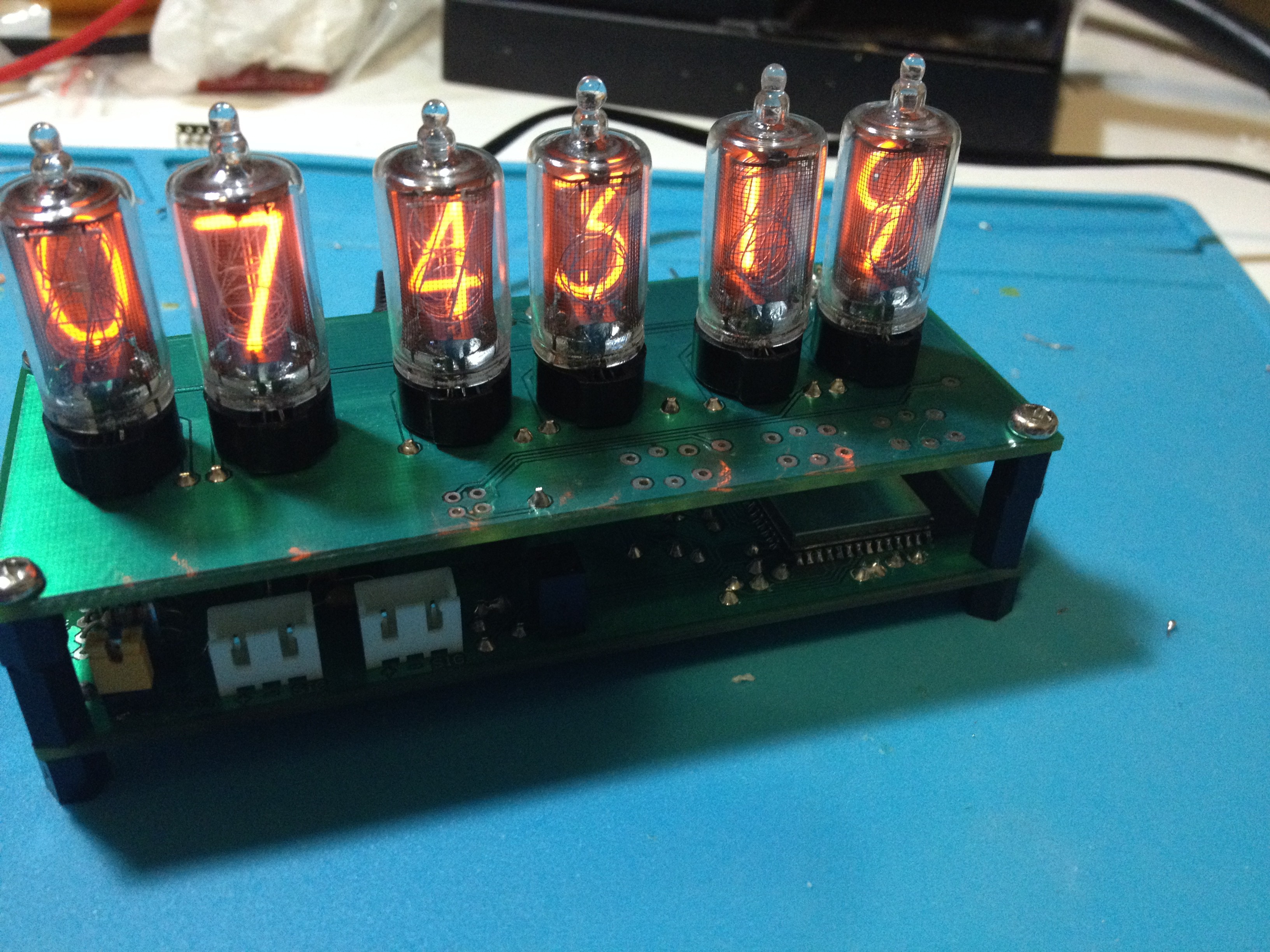
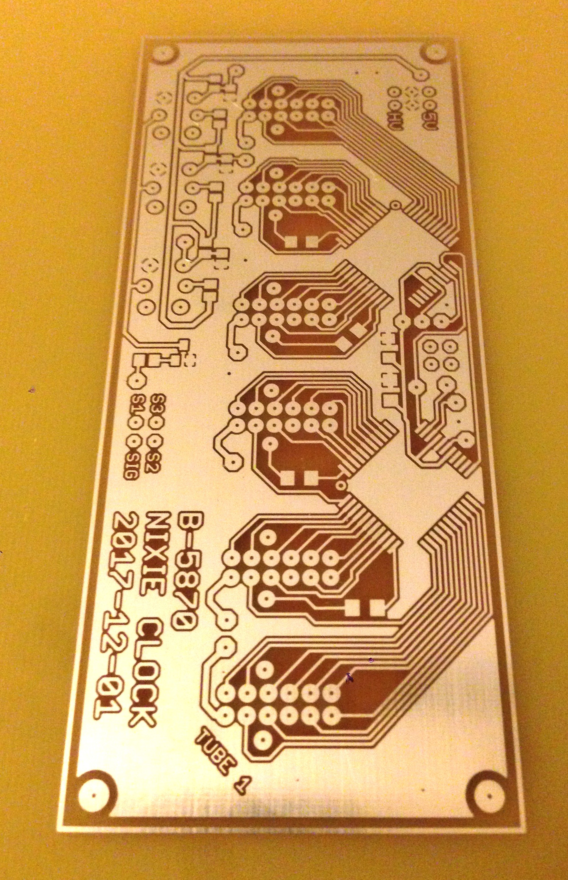
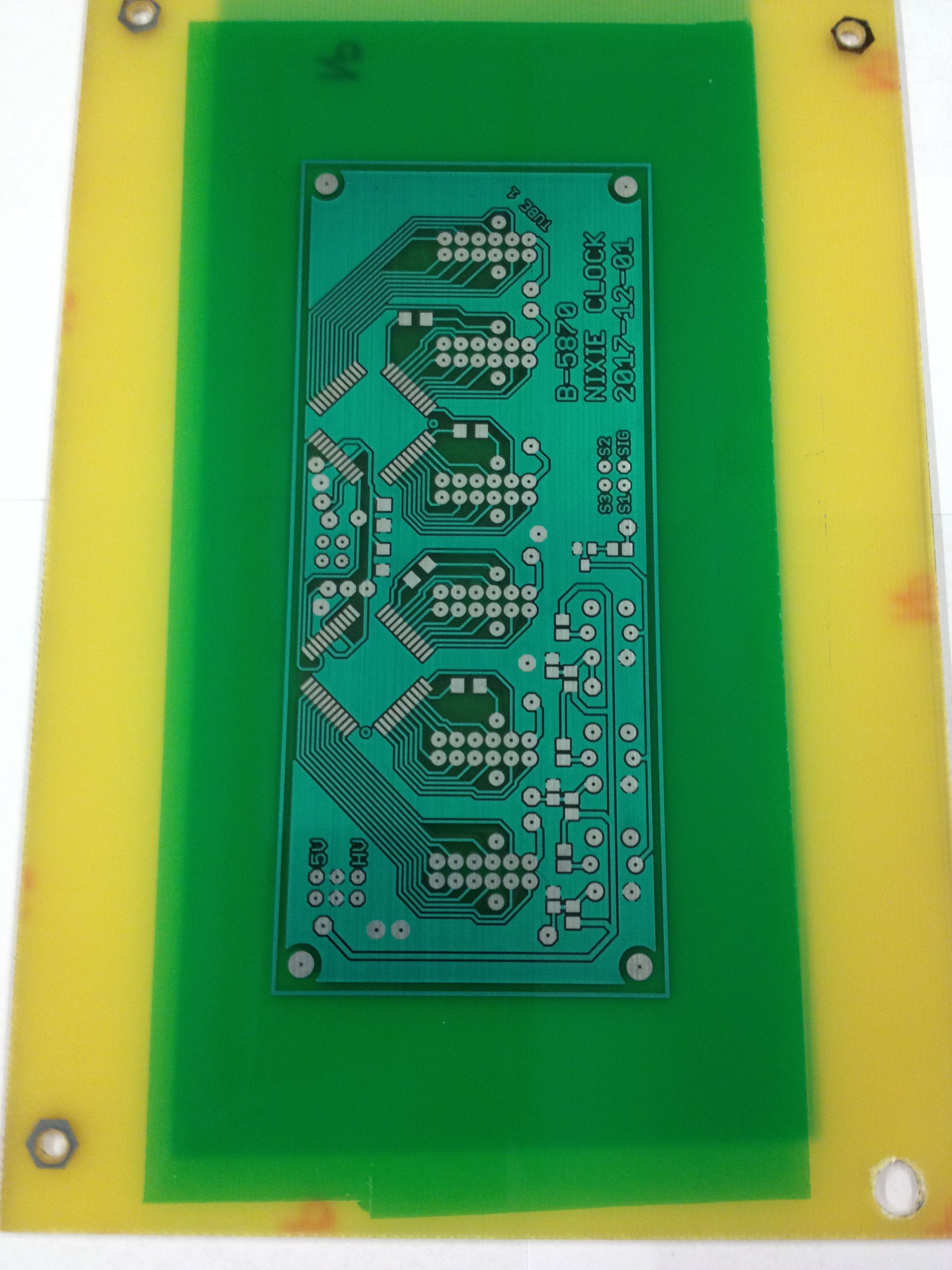
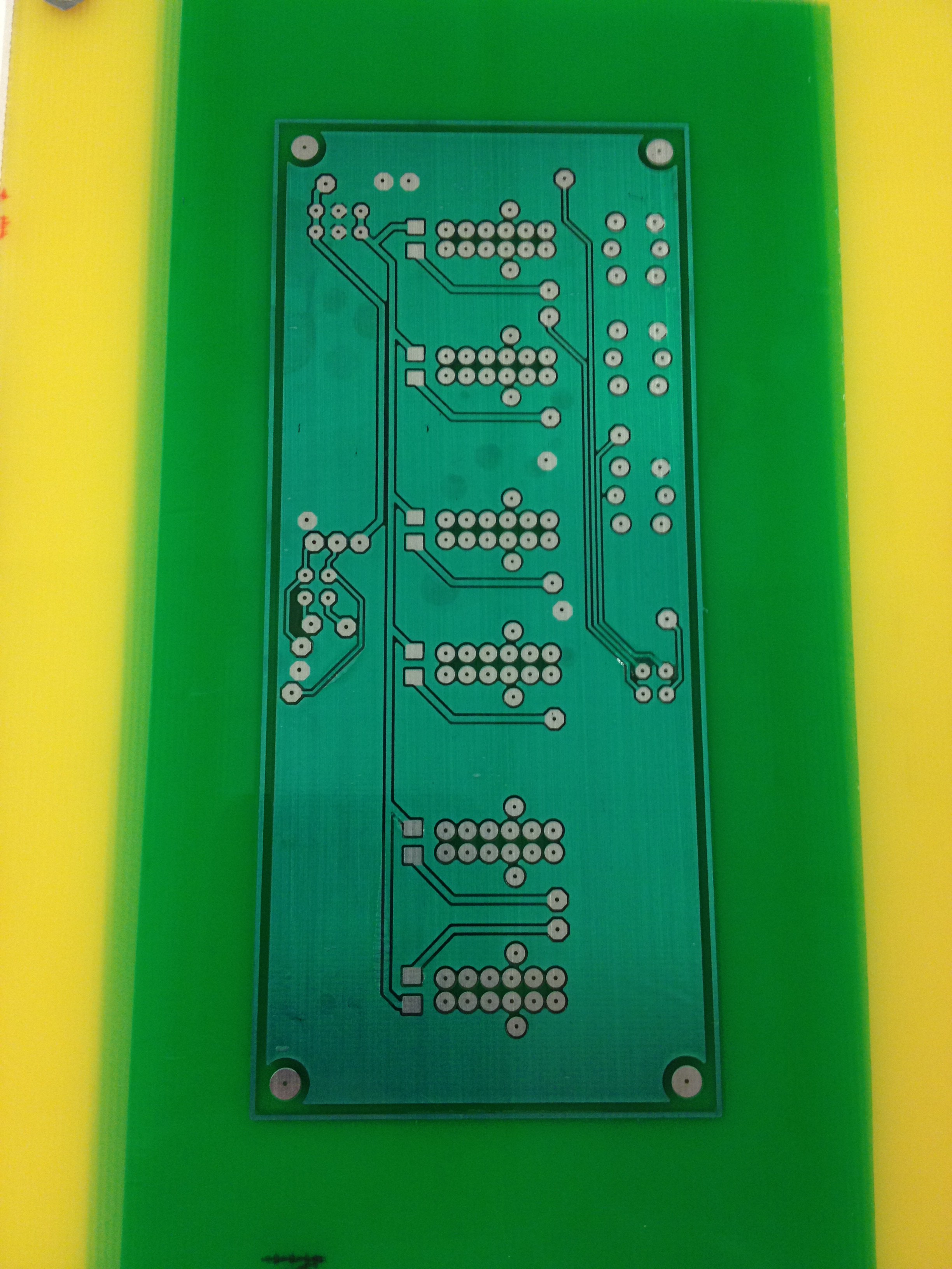
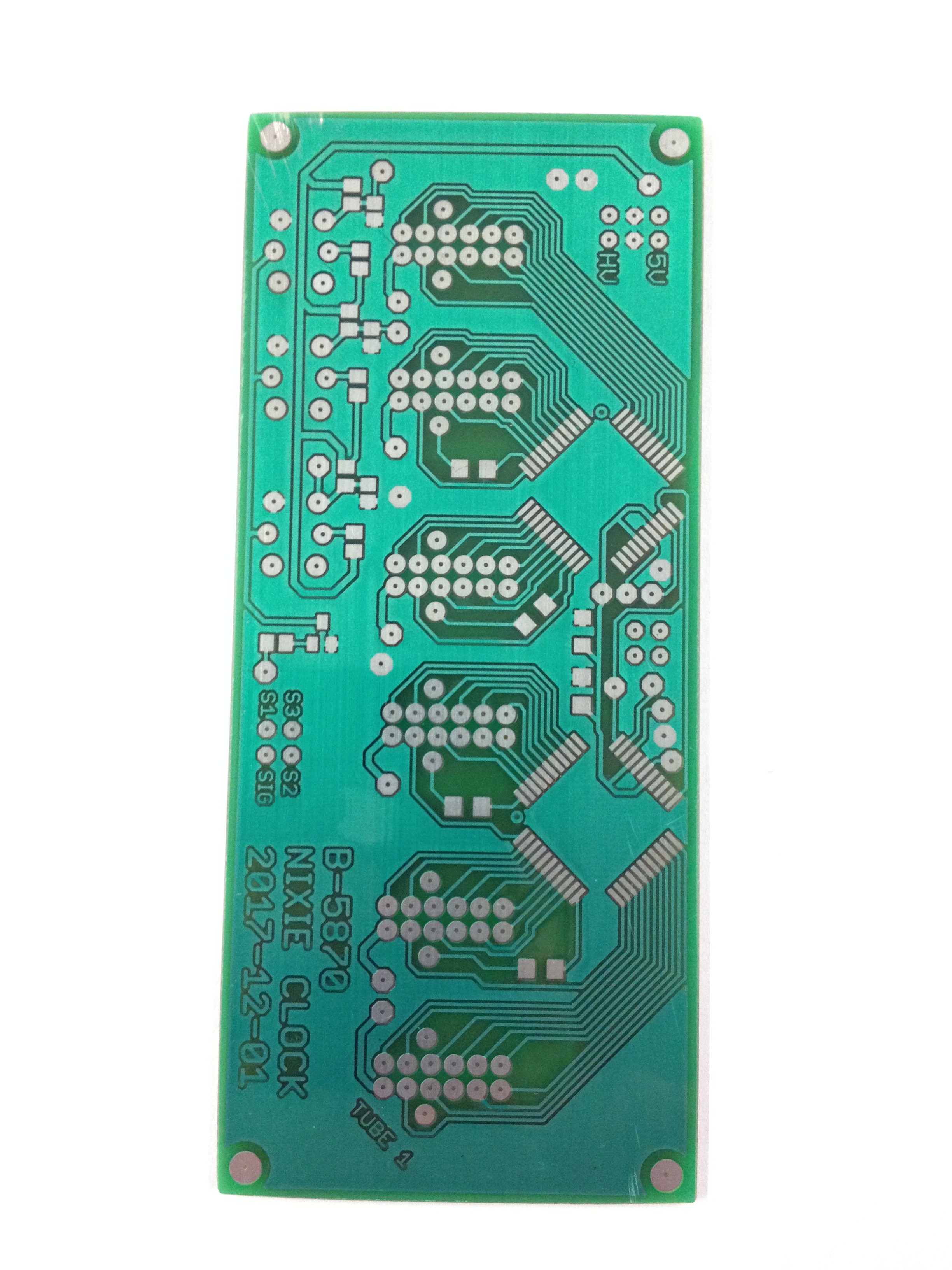
So from there all I had to do was design the rest of the circuit and make a couple circuit boards and then assemble it.
I Tested the look of it with a piece of black acrylic which seems to look pretty decent.
Now I need to make some sort of case for it!


 Alpenglow Industries
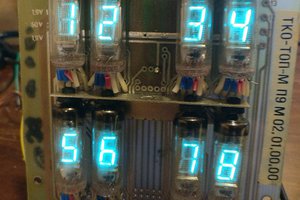
 cselzey
 Hulk
Hulk
Hi,
That's a really nice project.
I enjoy ESP projects and I was trying as well to design my own nixie clock (IN-14 tubes).
This week end I fully designed the pcb using the russian equivalent of 74141 binary to decimal encoder.
I also added mosfets to switch the anodes and allow multiplexing... It's not a nice pcb... a lot of wires and too much complexity !
And I found your design !
When you say : "On this clock I use 3.3V to run the HV5530s which is way below the recommended voltage (~10-12V) but still within the maximum operating range"
What does it exactly mean ? Do you power the chip with 3.3V ?
Or do you power it at 5V and interface it with the ESP32 at 3.3V ?
In both cases, does it really work well in all conitions ? Is it reliable ? (I am a lazy man and adding level shilfter is not cool !)
Another question, to help me decide if I change my current design, would you have a sample code to see only the HV5530 part ?
Thanks
JP