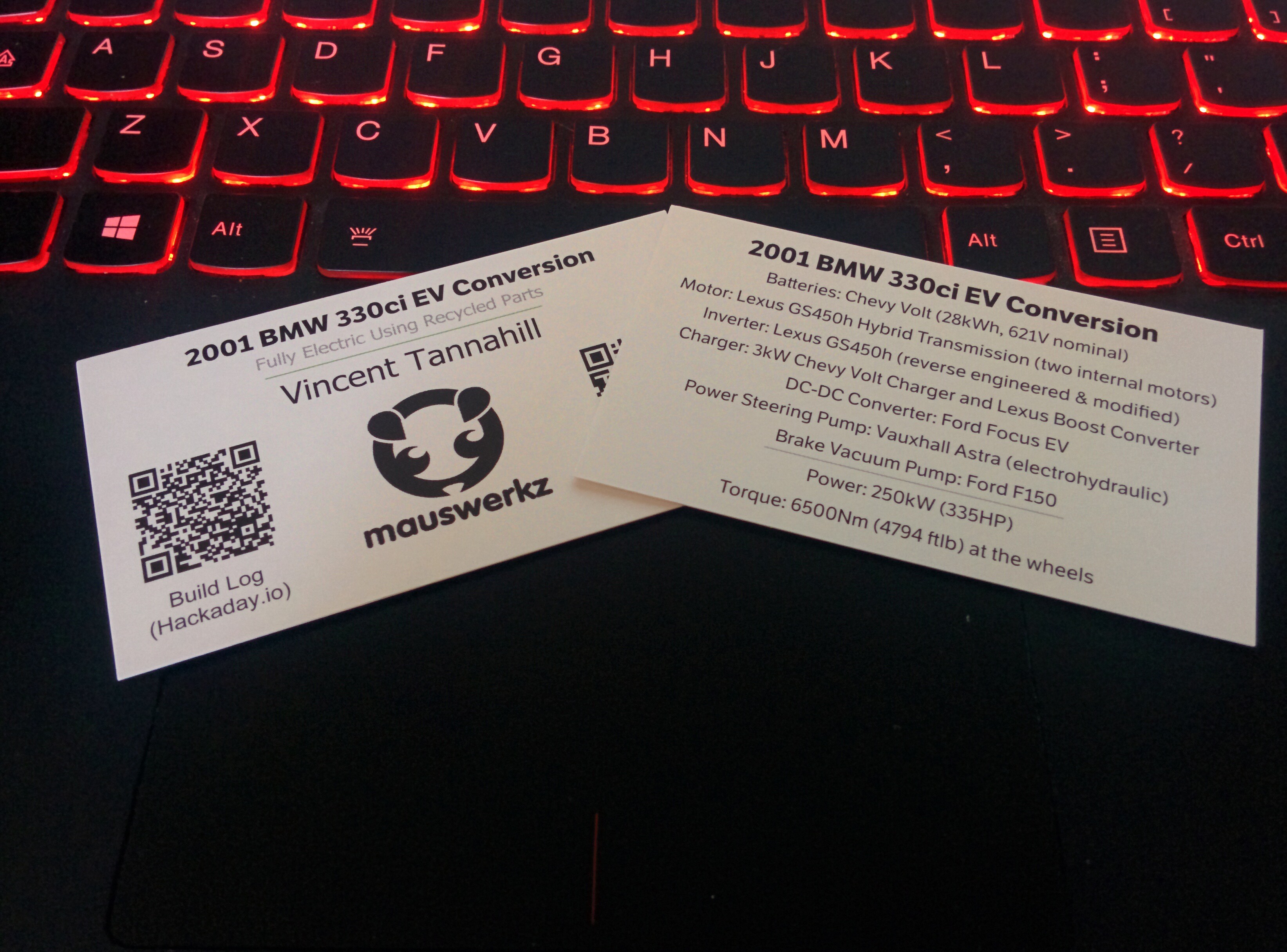
• Gateway ECU boards arrived

    mauswerkz05/26/2017 at 05:00 1 comment

    My last circuit board for my EV showed up! Just gotta populate, program, and wire it. Slides in to the slot the transmission ECU vacated.

    I'll 3D print an enclosure for it, but the tabs sticking out the side will protrude since they act like "rails", same as the ECU it's replacing.

    This is really the last piece to the puzzle to really unlock the full potential of this project. It will read the pedal position in a more reliable way that I am now, so drive will be smoother, and it will also control the transmission so I can use both gears. It will completely transform the driving experience!

    Finally, it will read the key position so that I don't need to use a laptop to start and stop the car.

  • FAQ Cards

    mauswerkz05/23/2017 at 02:38 0 comments

    Got some business cards printed to hand out to people when showing off my project at shows and the like. QR codes on the front for my Hackaday build log and my LinkedIn. On the back, a list of components used in the car and the key performance figures.

    I am not a graphic designer.

  • Making it touch-safe

    mauswerkz02/14/2017 at 05:17 2 comments

    I spent some time over the past weekend making my project touch-safe. With my newly aquired 3D printer and some orange PLA, I modeled up a 3-piece insulator/housing for the high-voltage inlet to the inverter. This had previously been simply two copper posts with cables connected to them. Now those posts are housed in PLA, with some semblance of water proofing, and fully enclosed so that it can be shown off without worry of someone touching a live conductor.

    Shown here is the full printed assembly, with copper installed. As well as the assembly steps. The base piece fits in to the oval shaped hole on the inverter, and is glued in to place with RTV.

    The first cable (+) connects to the shorter post, with O-ring around the sheath for sealing. There is sealing foam on both sides of the middle piece, which gets installed next.

    The other cable (-) gets installed on the remaining post and the cap is installed.

    4 screws are used to secure the stack together around the cables, engaging with captive nuts on the bottom layer. I'm very pleased with how it all goes together, even though it's not as water tight as I'd hope due to some bending of the cable lugs during crimping.


  • So much torque!

    mauswerkz12/17/2016 at 21:30 2 comments

    Sorted out the power limit on the Lexus inverter today. Two words: Holy Crap!

    This thing has so much torque I can barely touch the pedal and spin the tires (well, the left one at least). I'm going to have to get an M3 rear end and some better tires very promptly.

    It's just finishing touches at this point! So excited. I've never had a car that could do this before.

    (sorry for the vertical video. Obviously I wasn't the one recording the video).

  • First test drive!

    mauswerkz12/03/2016 at 22:46 1 comment

    The car moved under its own power for the first time today! I still have some hacking to do on the Lexus inverter communications as it seems that I'm stuck in some sort of limp mode, but it's enough to move the car. Check out the video below:


  • Reconsidering my inverter approach

    mauswerkz10/28/2016 at 04:31 0 comments

    The mechanical work is basically complete! I've been running in to trouble with the inverter. Reliable motor control is evading me, as is effective hardware protection. I've blown a few inverters at this point and am taking a step back to reconsider my plan for this final (and most important) piece of the puzzle.

    Instead of continuing forward with my own control board, I've decided to try my hand at reverse engineering the communications between the stock inverter and the hybrid controller. I figure that the engineers at Lexus/Toyota, with all the resources and expertise at their disposal, will have tuned the motor control far better that I could ever hope to in my garage. The hardware protections would also be as designed so the risk of blowing an inverter should be much lower than with my amateur attempts at stable IPM motor control. The only way for this project to be reliable enough to act as my daily driver with the occasional thrashing is to leverage the effort already put in to the powertrain in Japan.


    To that end, I spend last weekend with a borrowed 2007 Camry Hybrid. This car uses a very similar inverter (same control board inside, right down to the part number!), so I set up my Saleae logic analyzer and recorded the communication between the inverter and hybrid controller while performing a number of maneuvers and taking careful notes.

    There is a LOT of data to sift through, but I've managed to isolate the pieces of data which contain the torque commands for each MG, as well as some parts which look like "modes" or "states". I will spend some more time this coming weekend with one of my spare inverters to see if I can manage to get the hardware to respond to these commands. Hopefully I can get away with feeding it the same data I recorded, only varying the torque commands, and have it respond.

  • Nitty gritty, sweating the small stuff

    mauswerkz09/27/2016 at 04:04 5 comments

    I'm in to the details now. Lots of small things to get sorted out in preparation for the first drive. The down side is that there's a LOT of small things to do. The up side is that it really feels like I'm making good progress since I can get so many things done in a single day. The last two weekends have been extremely productive.

    Here's a quick video of the charge port LEDs reacting to the plug being inserted. The light comes on when the door is opened to illuminate the port. Once plugged in, the light "breathes" with the color ranging from red to green depending on the state of charge.

    The car is really coming together. I've managed to make enough torque to fight the parking brake and pull the hanging suspension back up in to the wheel wells. Getting some details wrapped up with hopes of moving the car under its own power next weekend.

    All the components mounted and the cooling system plumbed up. The clear tube is there to be able to confirm flow through the inverter and other power electronics and verify that bleeding of air is complete.

    This photo is before any tidying. The wiring is much more organized now, with well defined harnesses routed around the various components.

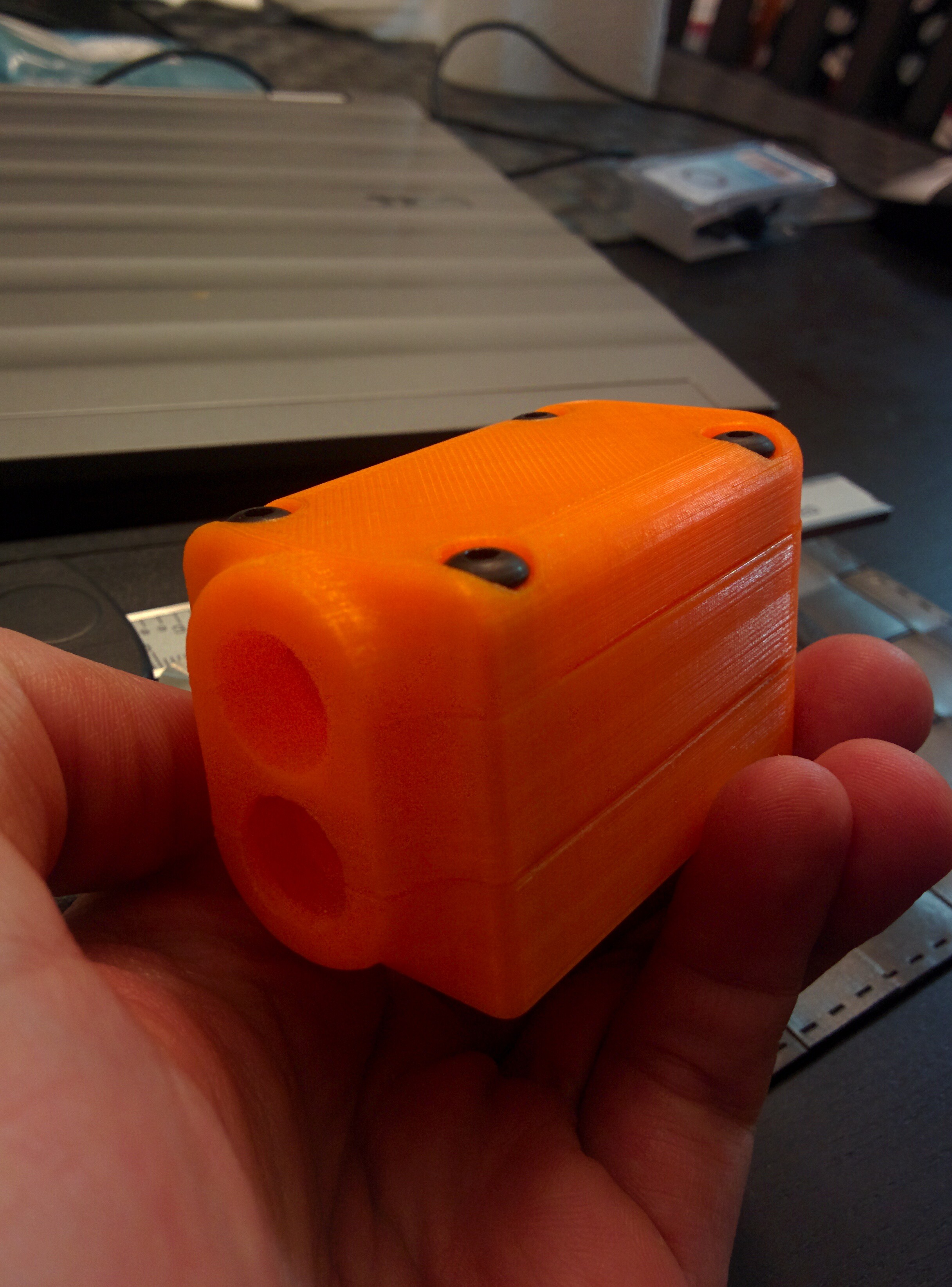
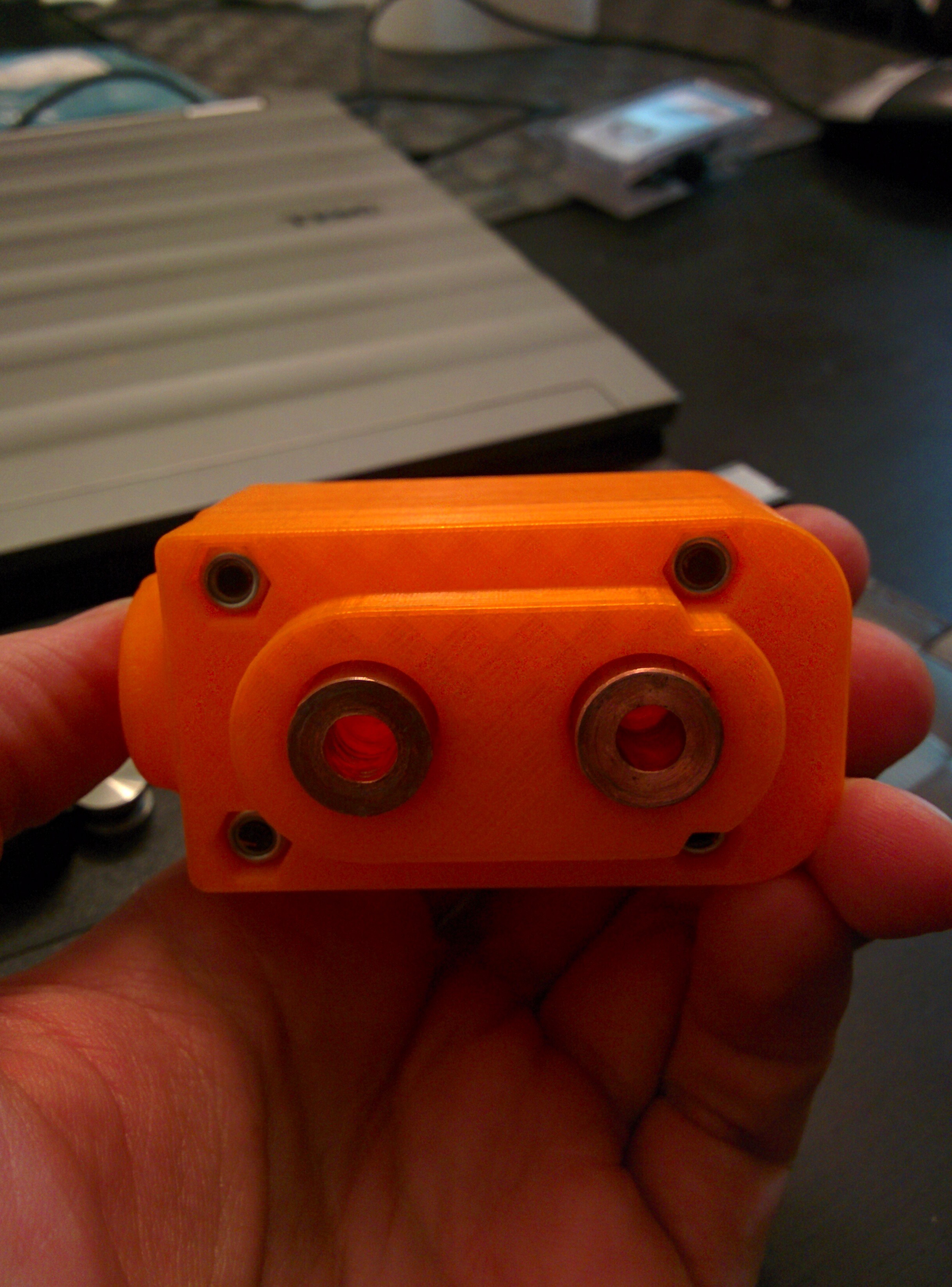
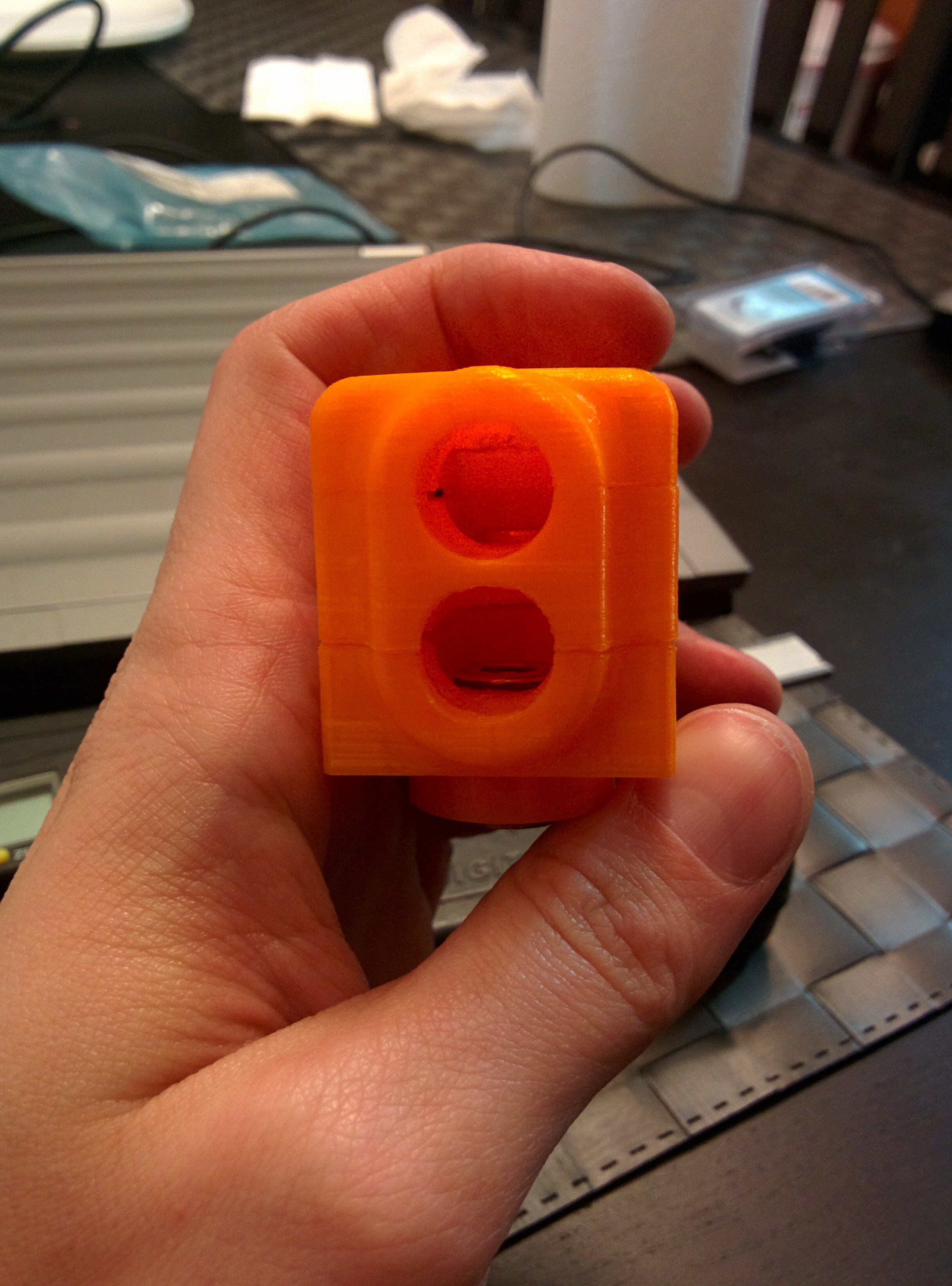
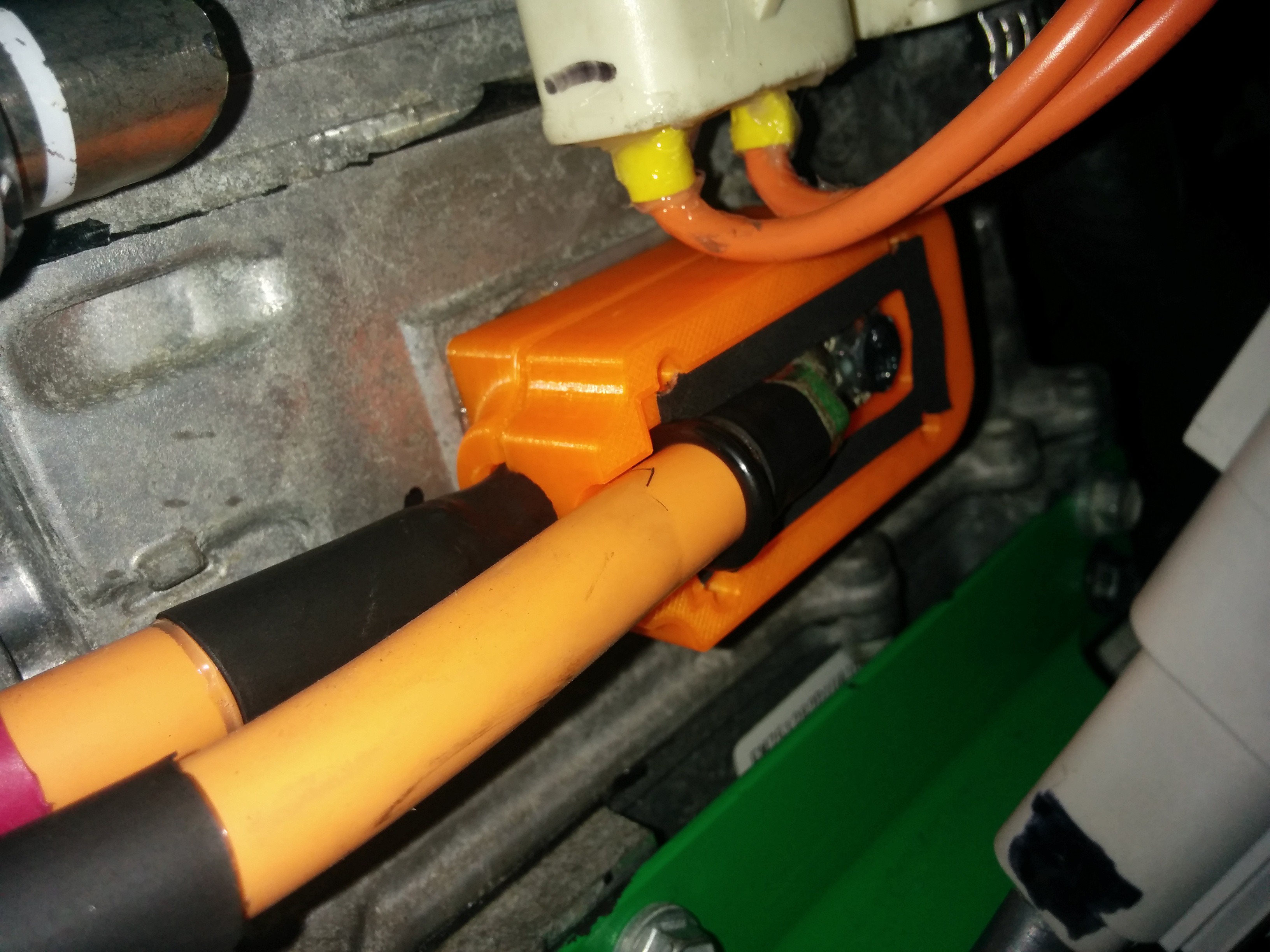
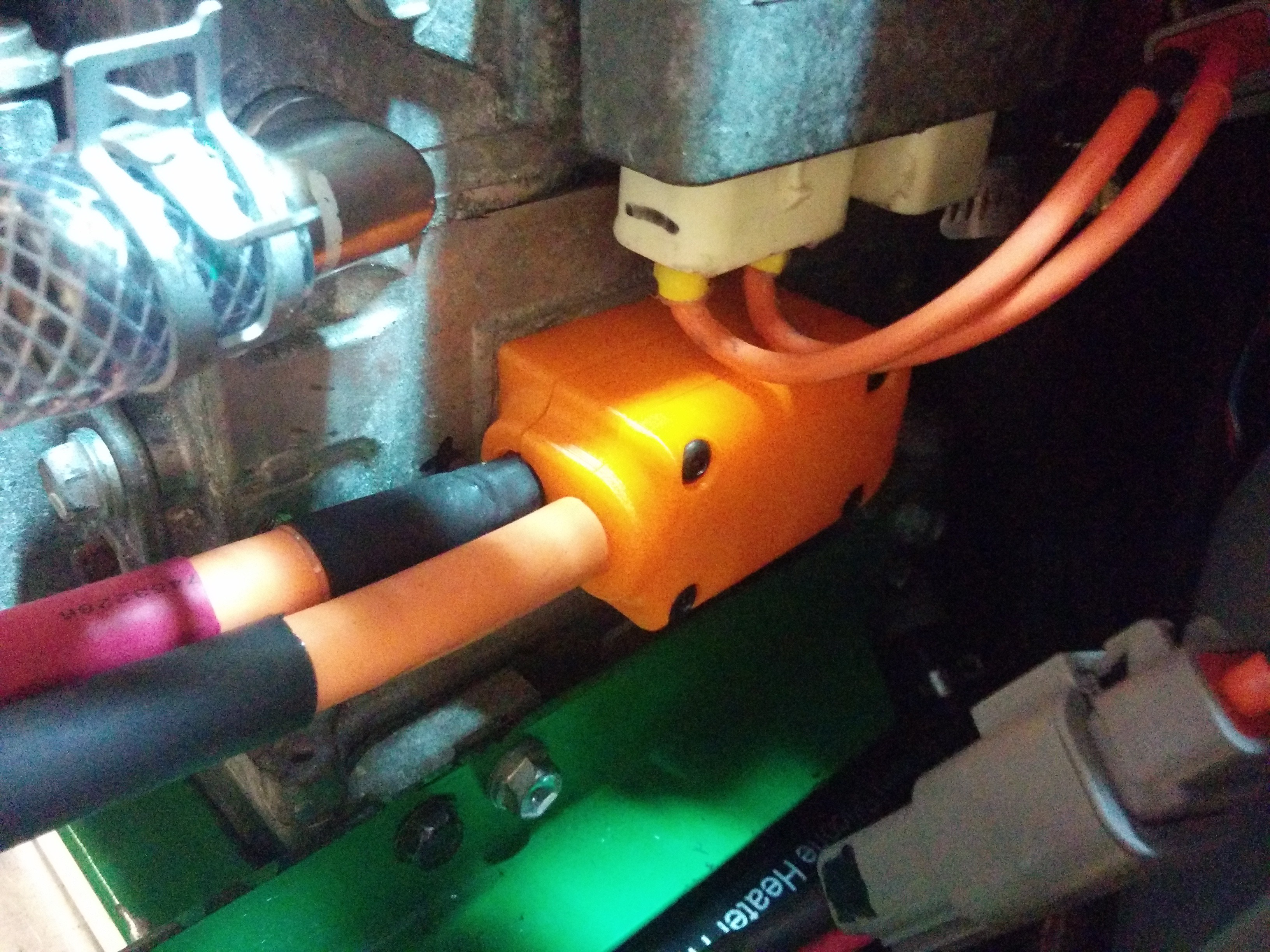
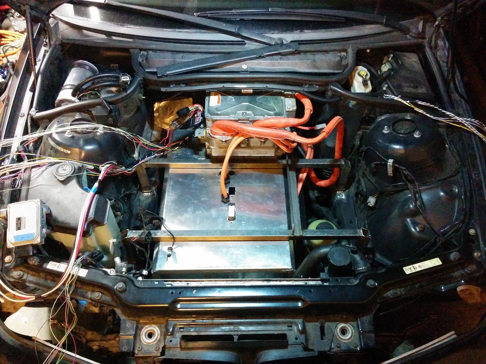
    I made a nice little panel for the top of the front battery. It holds the HV cables as well as the LV logic connections. It makes installing the cover for the front battery much easier than it used to be.


  • The Wheels Spin!

    mauswerkz07/07/2016 at 04:43 0 comments

    Not going to say much here except that this is a huge milestone for this project! The first wheel spin of an EV project is a special event. Very excited to get this thing wrapped up and on the road! Not far now.

  • Wrapping up the BMS Hardware

    mauswerkz07/04/2016 at 04:37 0 comments

    Got the BMS hardware mostly sorted out over the past couple days. All the wiring to the batteries and contactors is complete. Still have to sort out the wiring for the charge port (LEDs, Proximity, and Pilot).

    With the BMS CAN wiring complete I was finally able to get the BMS talking to the entire pack at once. Here's a quick screen capture of some of the distilled data from the Volt battery OEM BMS modules.

    For packs from two different cars and sitting for 8 months (I balanced them back in September), the voltage difference between the highest and lowest cell is very tight. I'm quite pleased!

    I made a quick video showing the BMS controlling the contactors, including precharge and welded contactor detection.

    Not much to see other than the voltage coming up. Most of the interesting stuff can be heard.

    During the closing sequence, there are 5 clicks. They are (in order):
    Battery negative contactor closing
    Battery pack split contactor closing
    Precharge relay closing
    Battery positive contactor closing
    Precharge relay opening.

    During discharge, you can hear 3 clicks:
    Battery positive contactor opening
    (Delay while it waits for voltage to drop, showing it actually opened and isn't welded)
    Battery negative contactor opening
    Battery pack split contactor opening

    The pack split contactor separates the rear battery pack from the front to keep voltages in the battery box at a lower level while sitting idle. When closed, it places both packs in series.

    Once that was sorted out, I put the battery cover on and am ready to finish wiring in the inverter. That should take a handful of hours, after which I may be ready to do the first spin of the motors in the car and on the actual battery pack!

    It's starting to feel like it's getting close now!

  • Wrapping up the mechanical fabrication

    mauswerkz06/30/2016 at 04:16 0 comments

    The mechanical fabrication is very close to being complete! So close in fact that the car came home with me this weekend (though on a trailer, not under it's own power). All that's left for the mechanical work is to finish the frame that straddles the front battery and to which the inverter, charger, DC-DC converter, and coolant heater mount to. And a return manifold for the coolant loops.

    Look how dirty it is! The only clean spots are the door windows (since they were rolled down since October) and the trunk lid (since it was open that whole time). The car was in a garage the whole time. This is all dust that collected on it in there.

    The brake vaccuum pump (from a Ford F150) is mounted in the empty cubby behind the front passenger side strut tower. The tank is an aluminum pipe with its ends capped. There's a GM manifold pressure sensor to monitor the vacuum level and help control the pump (same method I used on my previous EV conversion).

    The front battery box cover is in place. I have to finish the wiring inside it and terminate it all in to the connectors on top. There are 4 glands for HV cables as well. Two coming from the rear battery, and two heading to the inverter. The charger will mount to the left in this photo, DC-DC and coolant heater will mount on the right (above the steering pump). The inverter is mounted to the frame already, so that's where it will live. The small box in the far left of the frame is the transmission oil pump controller. I need to shorten the wiring going to that and mount it somewhere with good airflow.