This video shows the initial PID tuning and a simple adjustable tilt angle setpoint to induce forward and reverse motion. Still a lot of work to be done on tuning.
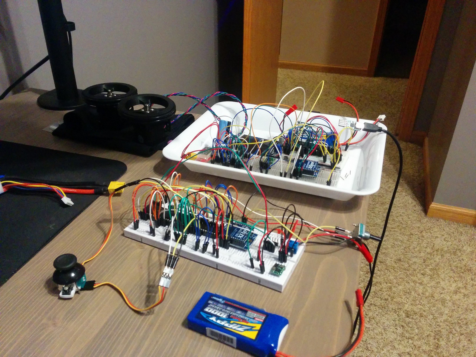
Bread Boarding:
First thing was to decide on components and breadboard everything to get it all working together. I have breadboarded before but these were my first attempts at anything with some complexity. Believe it or not these are some of my tidier breadboard jobs. One is the remote control and the other is the balance bot brains.
Component Integration:
Figuring out how to communicate with the I2C sensors was not trivial for me, I think it took me about 3 days before I finally got both the gyro and accel working correctly. I did enough coding to read the sensors, get my XBees to talk to each other and control the stepper motors. Then there was the matter of coding the AHRS and fusing the gyro and accel with a very simple to implement complementary filter.
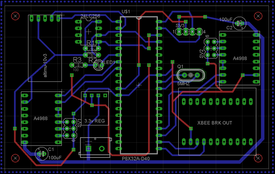
PCB Design:
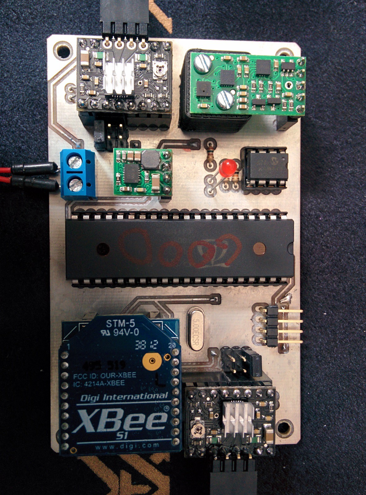
EagleCad is a fantastic piece of software with a fairly capable free version. Tutorials were easy to come by and after three or four attempts I had manually routed what I considered a decent board. This is a photo of the main control board of the robot. It carries the Prop, eeprom, stepper drivers, IMU, and XBee. I also designed a remote control.
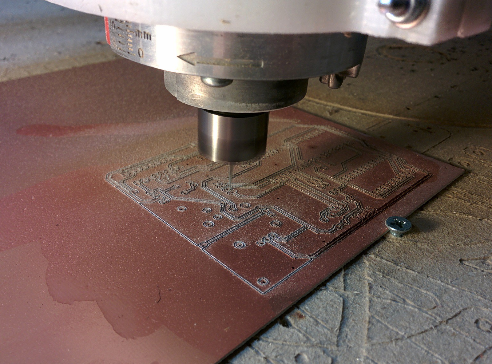
Isolation Milling:
One of the beautiful things about EagleCad is that you can fairly simply generate gcodes for isolation milling of PCBs. The more difficult part is actually milling the boards. This was my first attempt. I knew that getting the Copper clad board perfectly flat was going to be difficult especially since I would have to flip the board. I decided to use 10 degree V carving bits for my first attempt due to having to deal with slight warp in the copper clad and also induced flex from fixing the board to the table. I figured the narrower the V bit the higher the variance in flatness could be. While these bits would cut traces they would not leave clean edges and some traces were nearly cut all the way through the board. This is my first attempt. I even tried a little oil to aid in cutting. Its pretty easy to see this is not a great example of isolation milling.
The solution? Build a vacuum table of course.
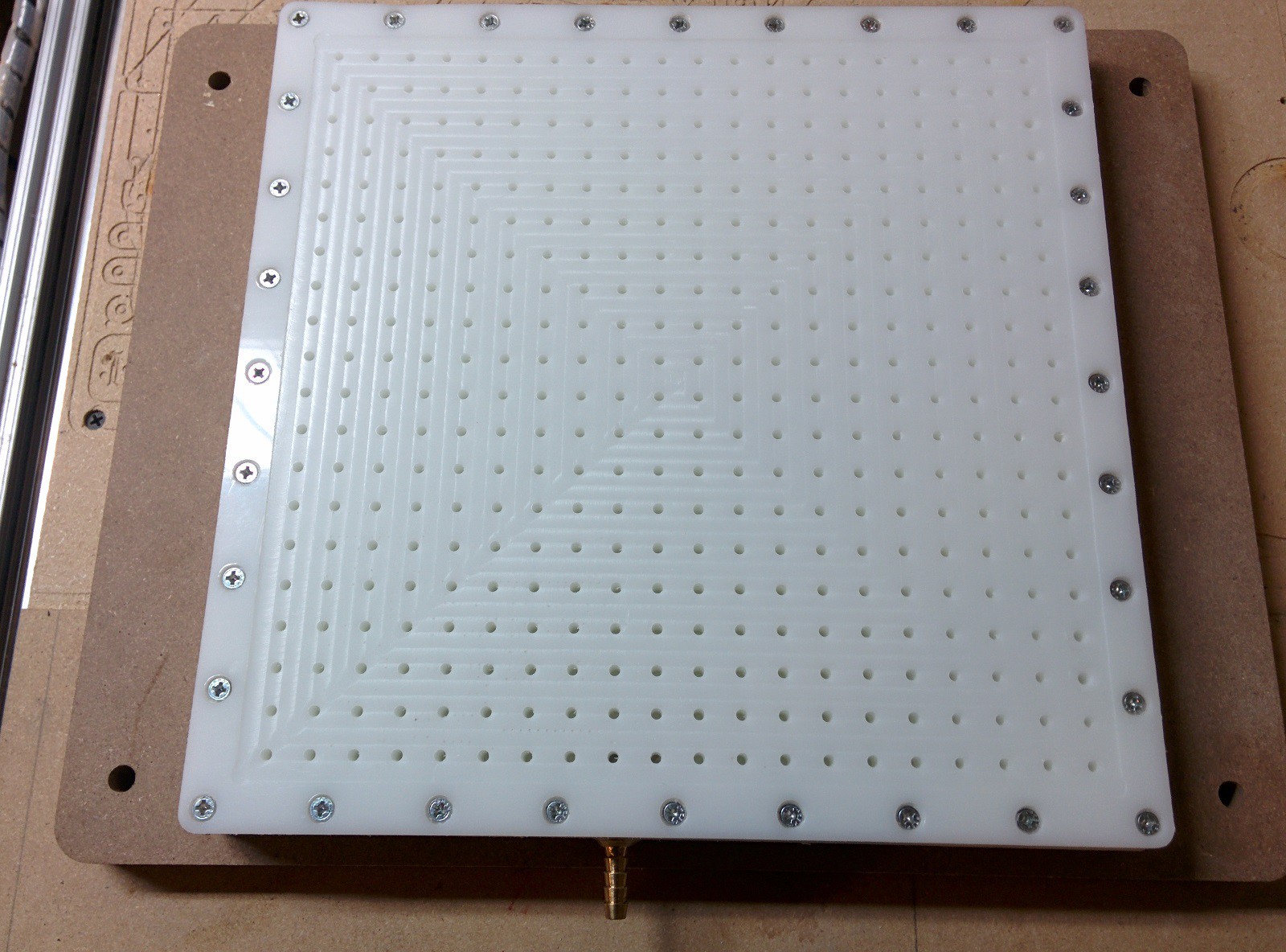
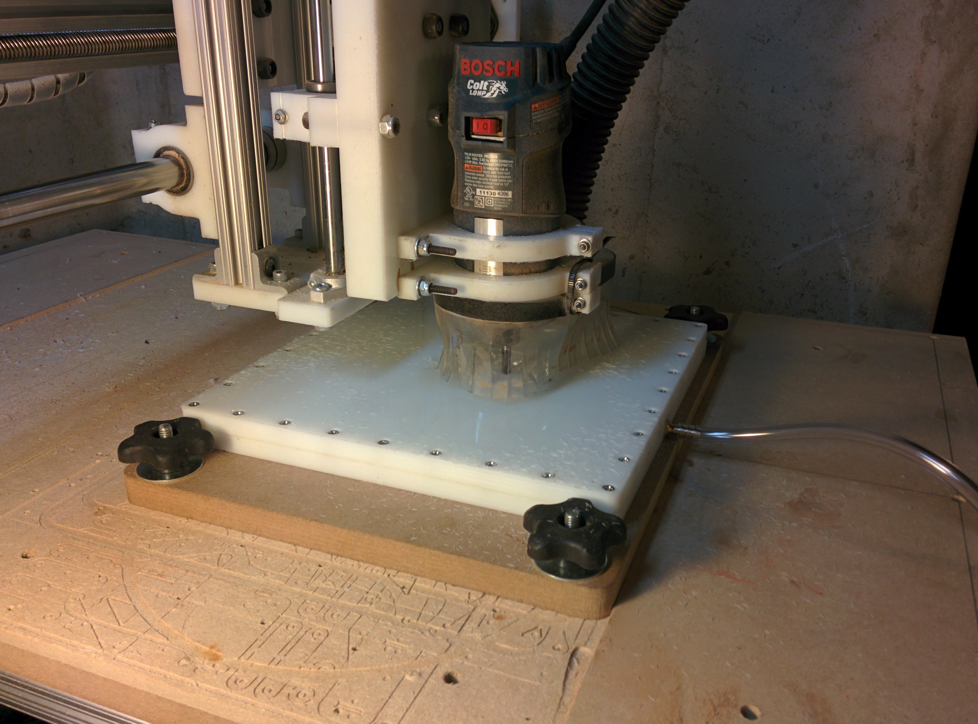
This is the second iteration of my vacuum table. The first version used MDF as the bottom part of the vacuum chamber. It turns out that even after 10 coats of polyurethane, there are enough microscopic pores in the MDF to completely ruin your vacuum. This version below uses two sandwiched pieces of 1/2" HDPE for the vacuum chamber. This photo shows the milling of the pocket in the face of the table to ensure it is perfectly flat in reference to the router.
Here are the starting cuts of my first successful circuit board. Holes in the vacuum table not covered by copper clad are sealed with masking tape, I managed to pull 15 inches of vacuum although I'm certain 5 would suffice. Since I now have a perfectly flat surface to machine I switched to 60 degree 0.1mm vbits, they cut much better than the 10 degree bits.
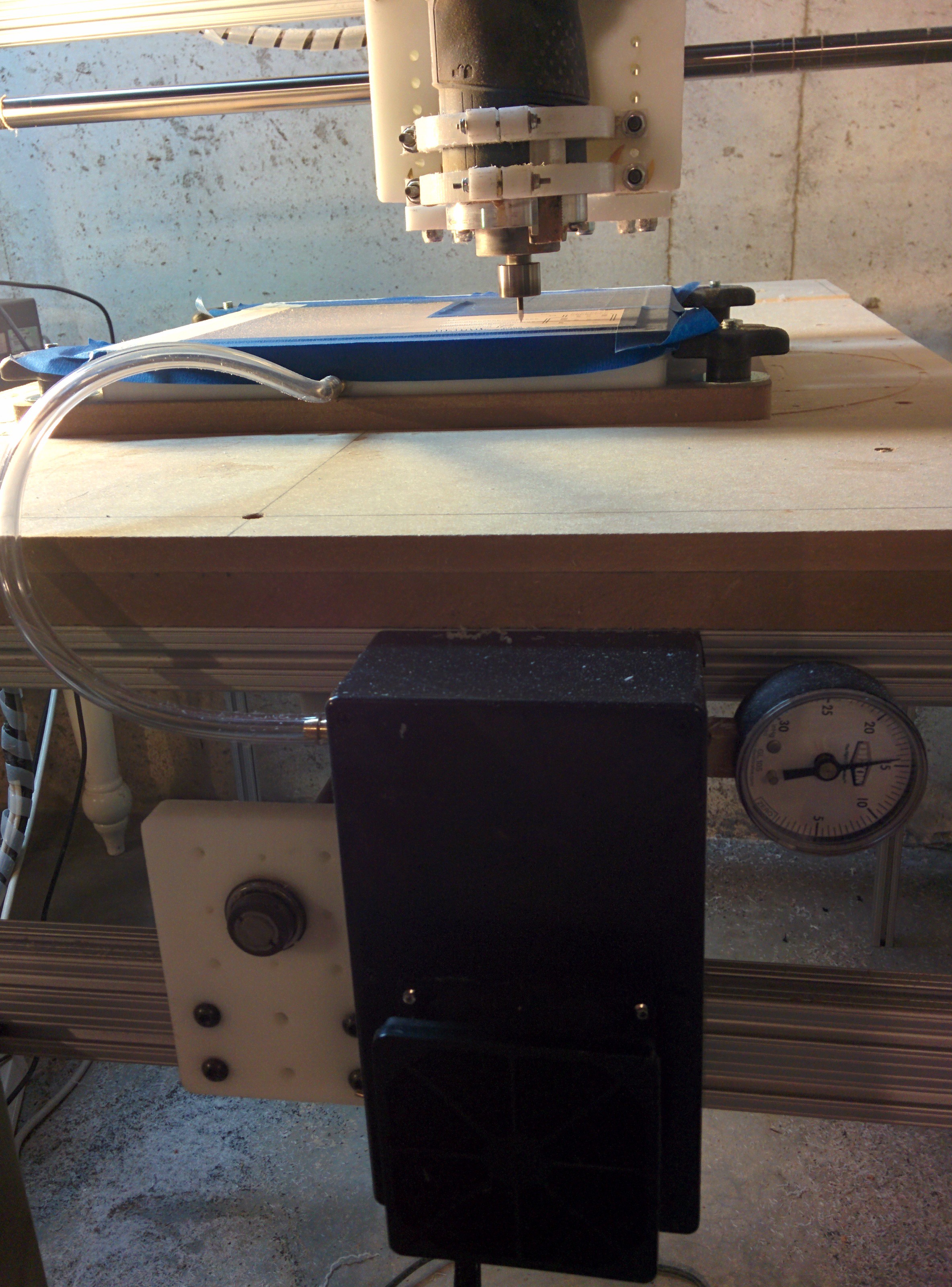
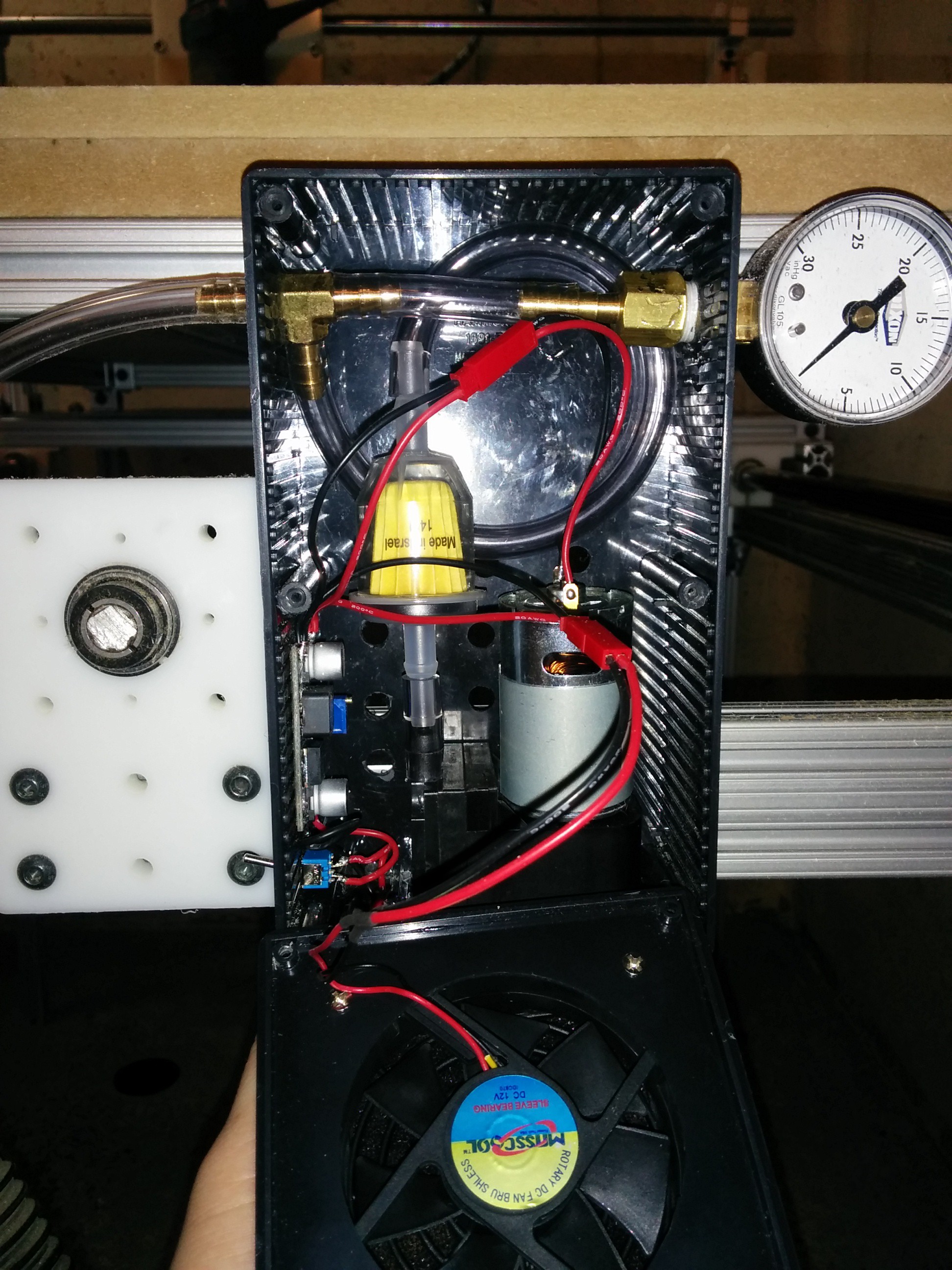
The vacuum pump is a simple 12v $15 pump available from sparkfun (https://www.sparkfun.com/products/10398) mine is capable of pulling 21" Hg of vacuum which is more than enough for my purposes. The vacuum is not intended to hold the board in place although it does. My goal with the vacuum table was to pull the warp out of the copper clad boards in order to give me a perfectly flat surface to machine. Inside the box is a fuel filter intended for a lawn tractor, it should filter out any dust or machining debris before reaching the pump.
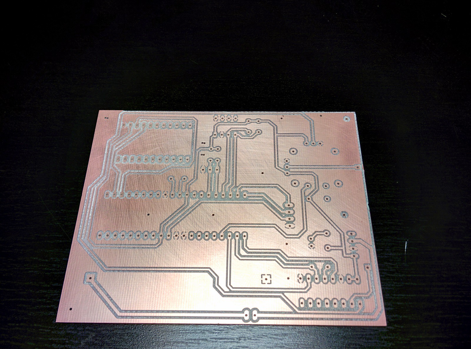
Here is one of the finished boards.
And here is one that has been tinned and assembled. It's amazing what a mess of wires on a breadboard can become. I will say that soldering a circuit board without a solder mask is a little bit more difficult.
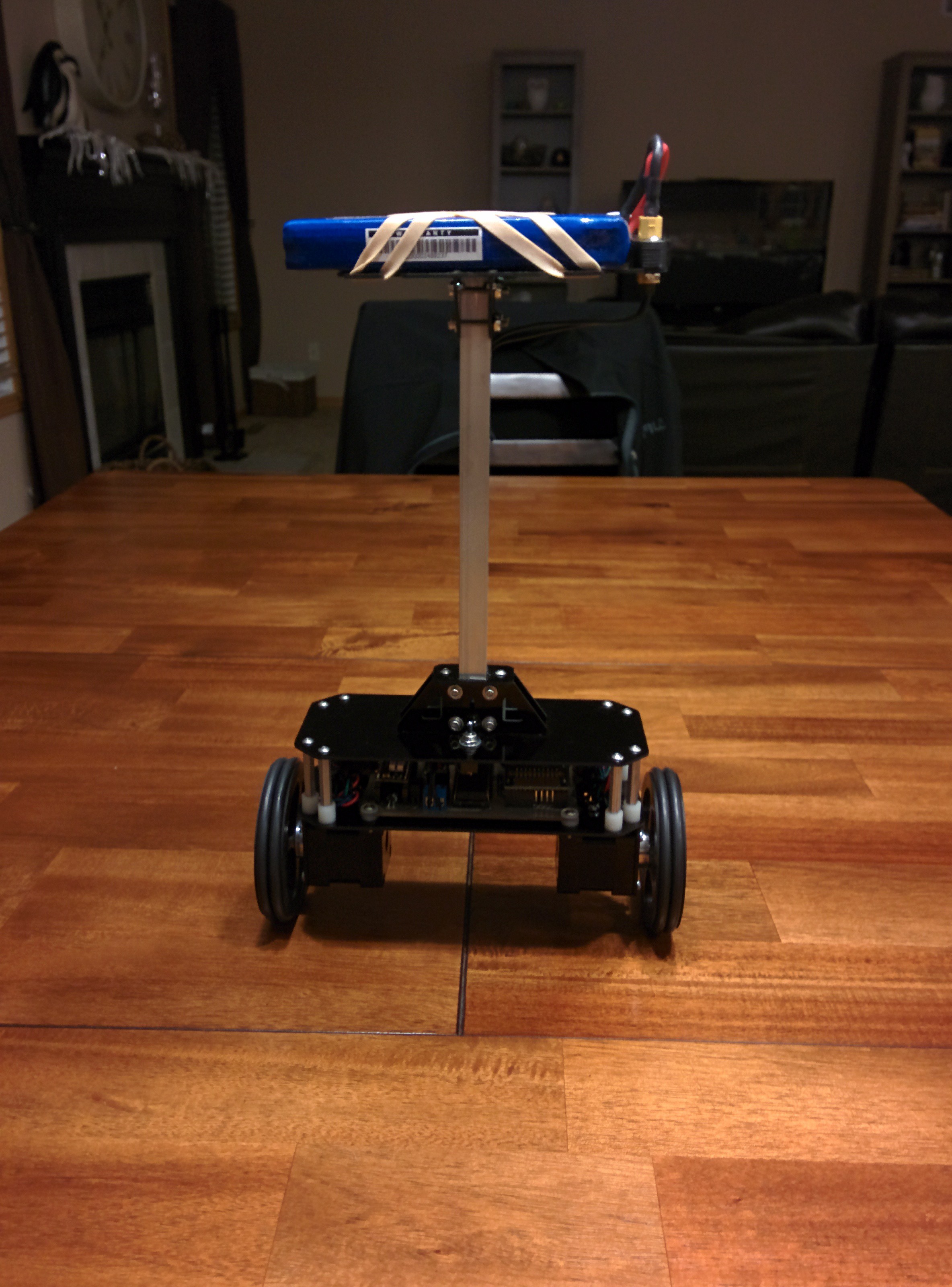
Bot Assembly:
This was the easiest part. The frame of the B-Bot is made from G10 cut on my CNC router. The mast is 1/2" aluminum square tubing.
Here is the mast support. This is one...
Read more »
 Alvaro Ferrán Cifuentes
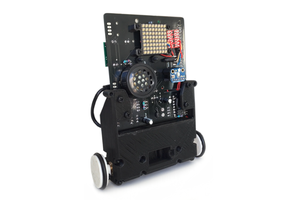
 Ben Steer
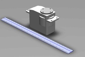
 Nyles
Nyles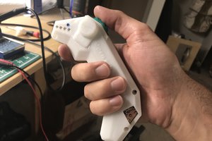
 Timo Birnschein
Terrific write up!