This video shows the initial PID tuning and a simple adjustable tilt angle setpoint to induce forward and reverse motion. Still a lot of work to be done on tuning.
Bread Boarding:
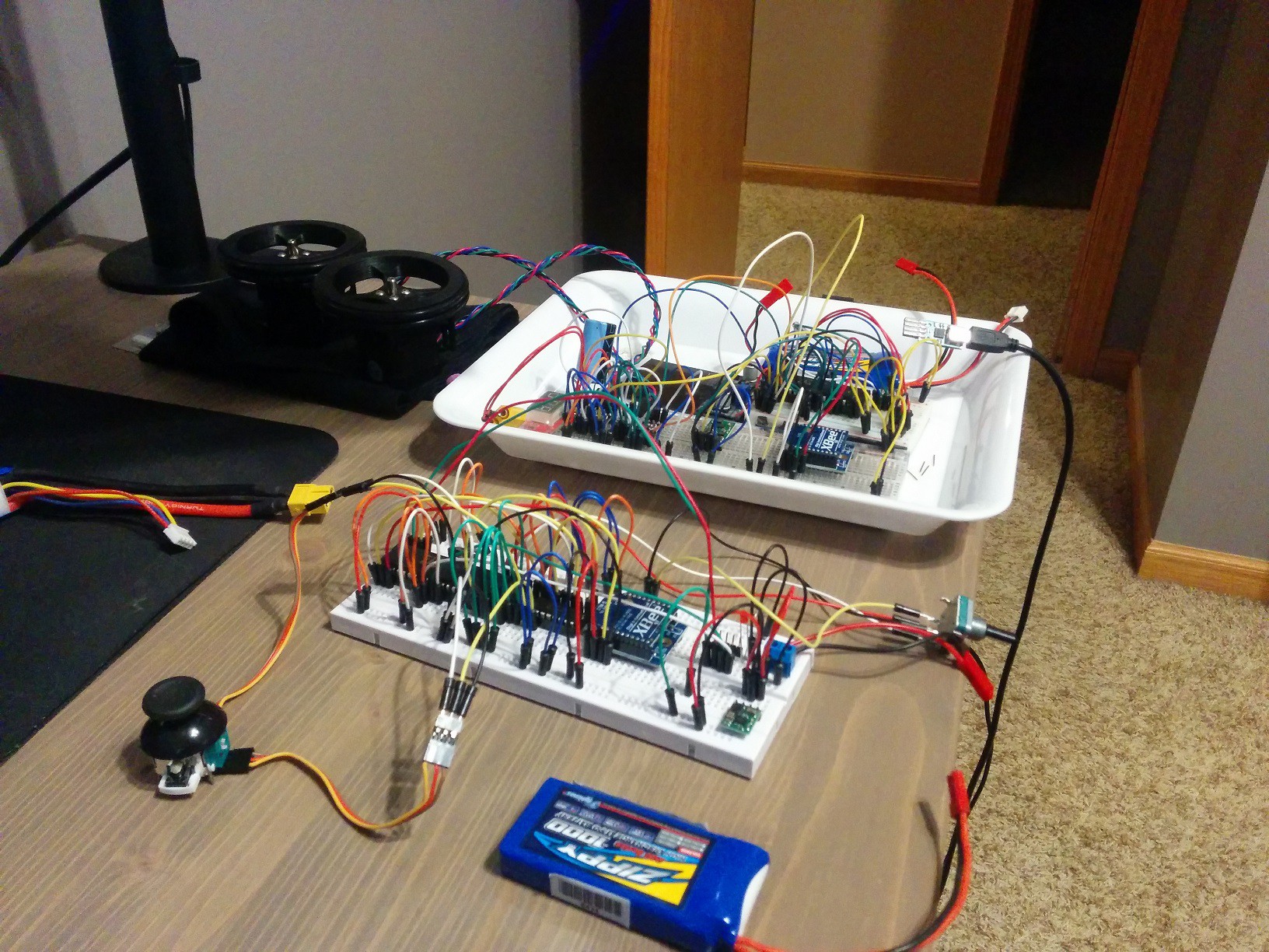
First thing was to decide on components and breadboard everything to get it all working together. I have breadboarded before but these were my first attempts at anything with some complexity. Believe it or not these are some of my tidier breadboard jobs. One is the remote control and the other is the balance bot brains.
Component Integration:
Figuring out how to communicate with the I2C sensors was not trivial for me, I think it took me about 3 days before I finally got both the gyro and accel working correctly. I did enough coding to read the sensors, get my XBees to talk to each other and control the stepper motors. Then there was the matter of coding the AHRS and fusing the gyro and accel with a very simple to implement complementary filter.
PCB Design:
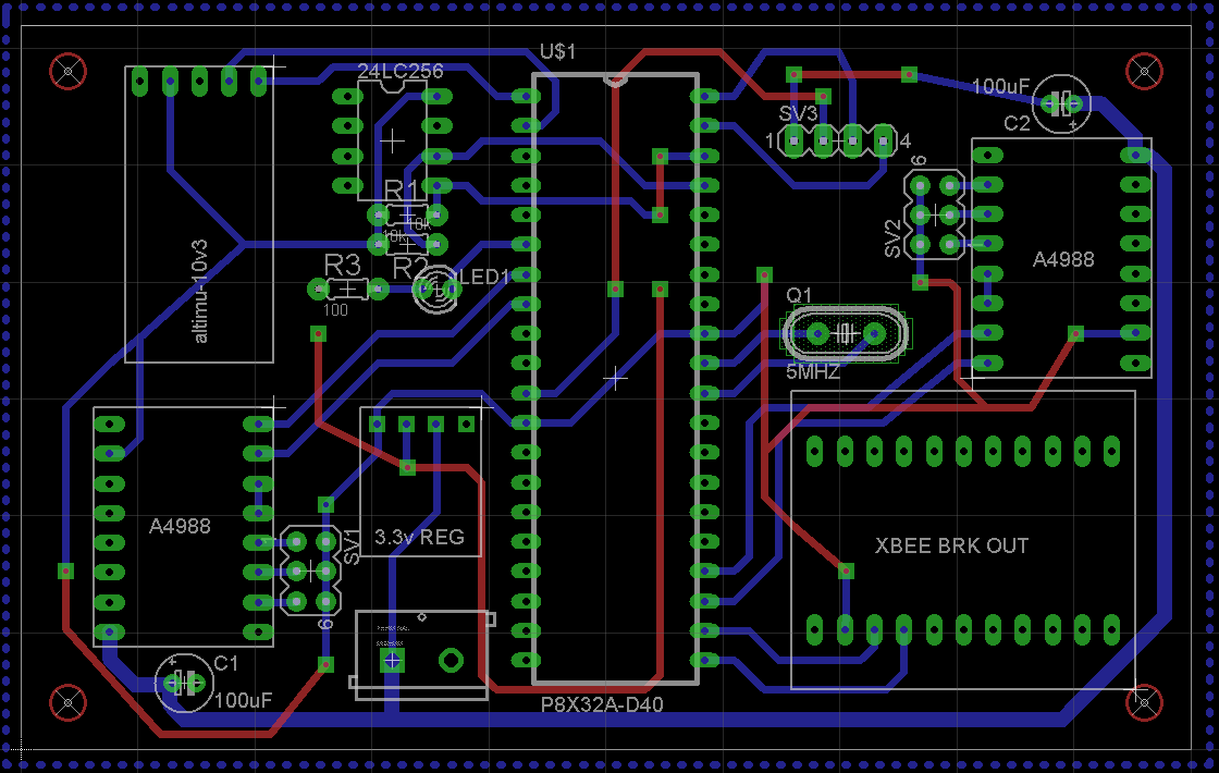
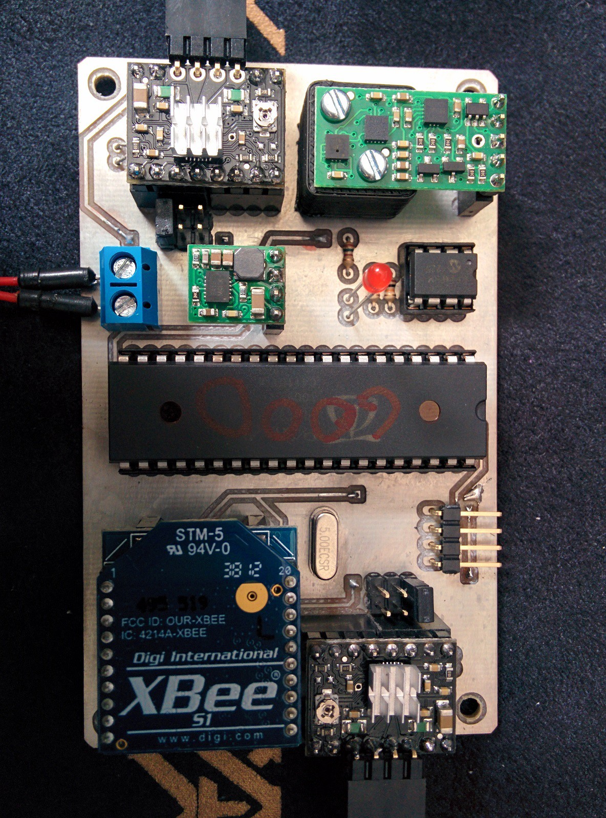
EagleCad is a fantastic piece of software with a fairly capable free version. Tutorials were easy to come by and after three or four attempts I had manually routed what I considered a decent board. This is a photo of the main control board of the robot. It carries the Prop, eeprom, stepper drivers, IMU, and XBee. I also designed a remote control.
Isolation Milling:
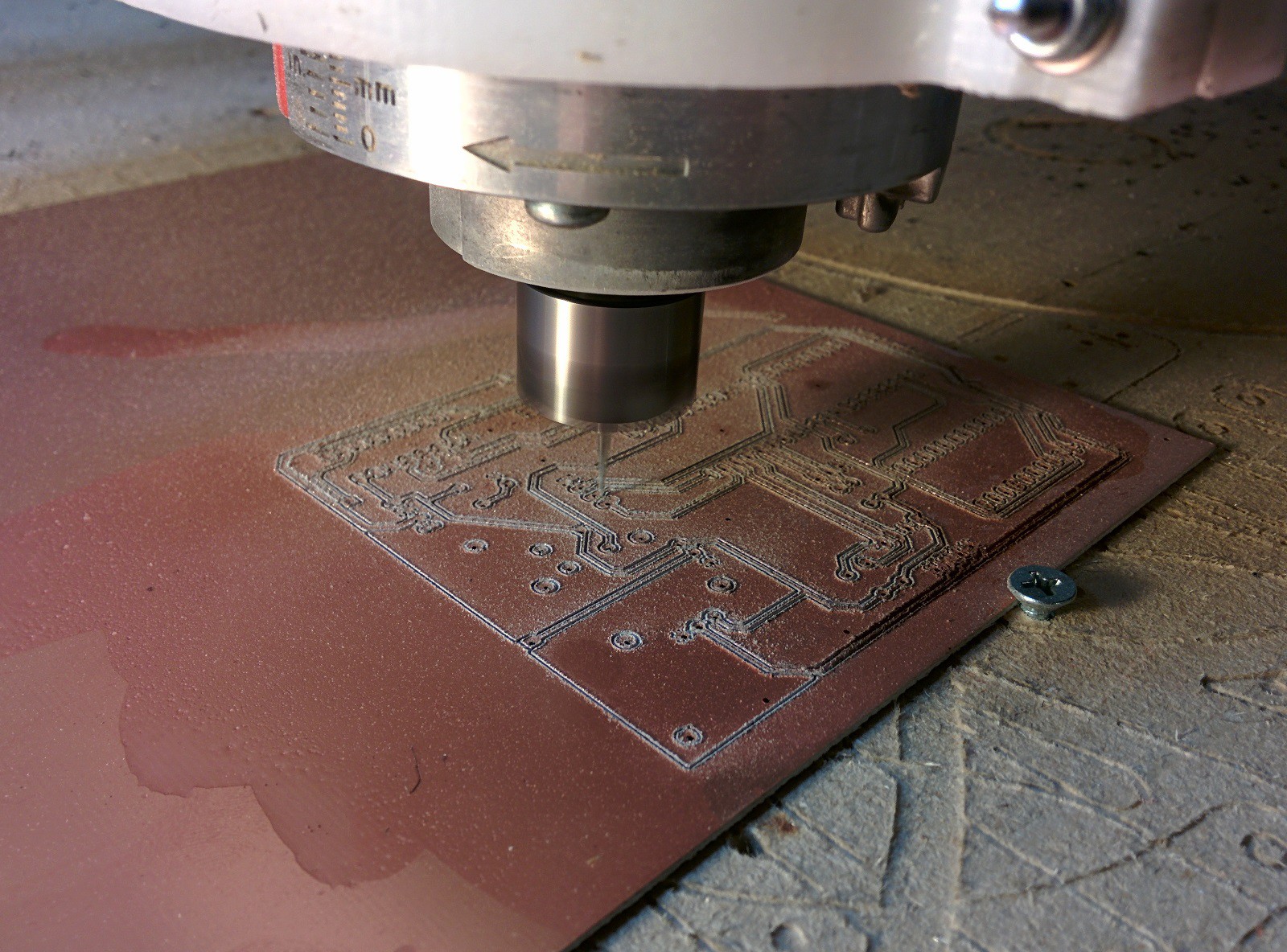
One of the beautiful things about EagleCad is that you can fairly simply generate gcodes for isolation milling of PCBs. The more difficult part is actually milling the boards. This was my first attempt. I knew that getting the Copper clad board perfectly flat was going to be difficult especially since I would have to flip the board. I decided to use 10 degree V carving bits for my first attempt due to having to deal with slight warp in the copper clad and also induced flex from fixing the board to the table. I figured the narrower the V bit the higher the variance in flatness could be. While these bits would cut traces they would not leave clean edges and some traces were nearly cut all the way through the board. This is my first attempt. I even tried a little oil to aid in cutting. Its pretty easy to see this is not a great example of isolation milling.
The solution? Build a vacuum table of course.
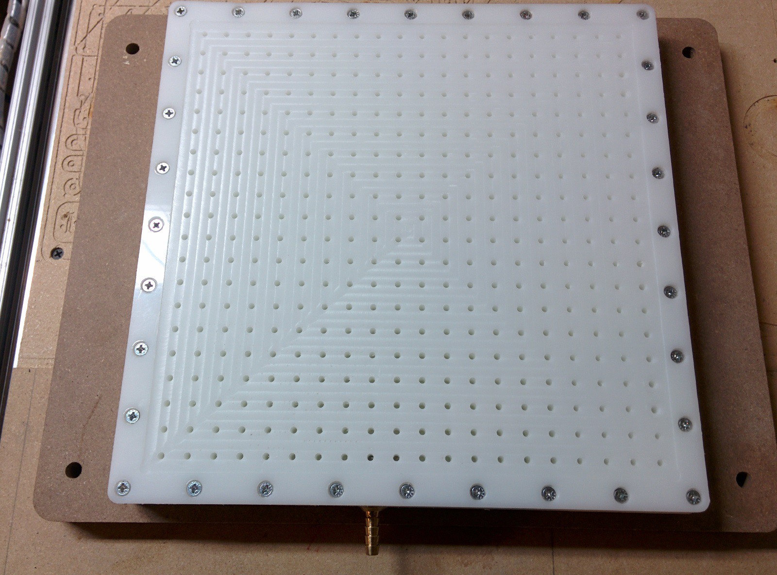
This is the second iteration of my vacuum table. The first version used MDF as the bottom part of the vacuum chamber. It turns out that even after 10 coats of polyurethane, there are enough microscopic pores in the MDF to completely ruin your vacuum. This version below uses two sandwiched pieces of 1/2" HDPE for the vacuum chamber. This photo shows the milling of the pocket in the face of the table to ensure it is perfectly flat in reference to the router.
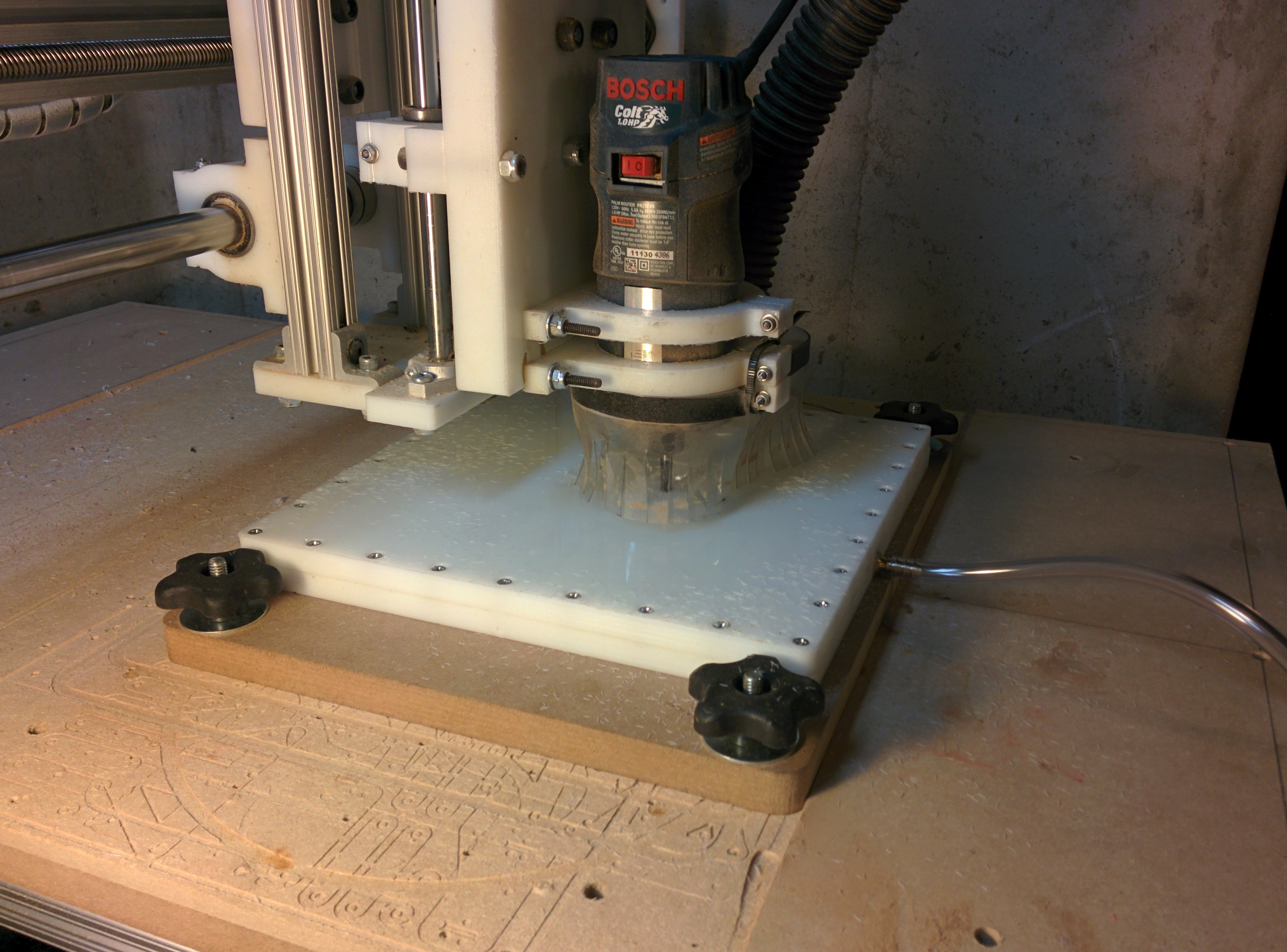
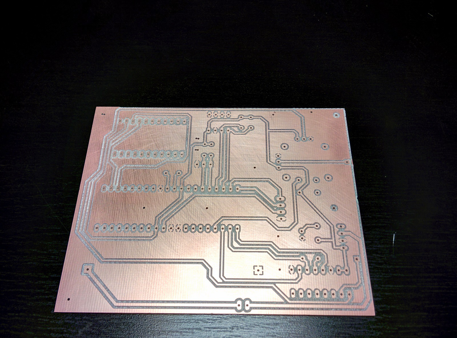
Here are the starting cuts of my first successful circuit board. Holes in the vacuum table not covered by copper clad are sealed with masking tape, I managed to pull 15 inches of vacuum although I'm certain 5 would suffice. Since I now have a perfectly flat surface to machine I switched to 60 degree 0.1mm vbits, they cut much better than the 10 degree bits.
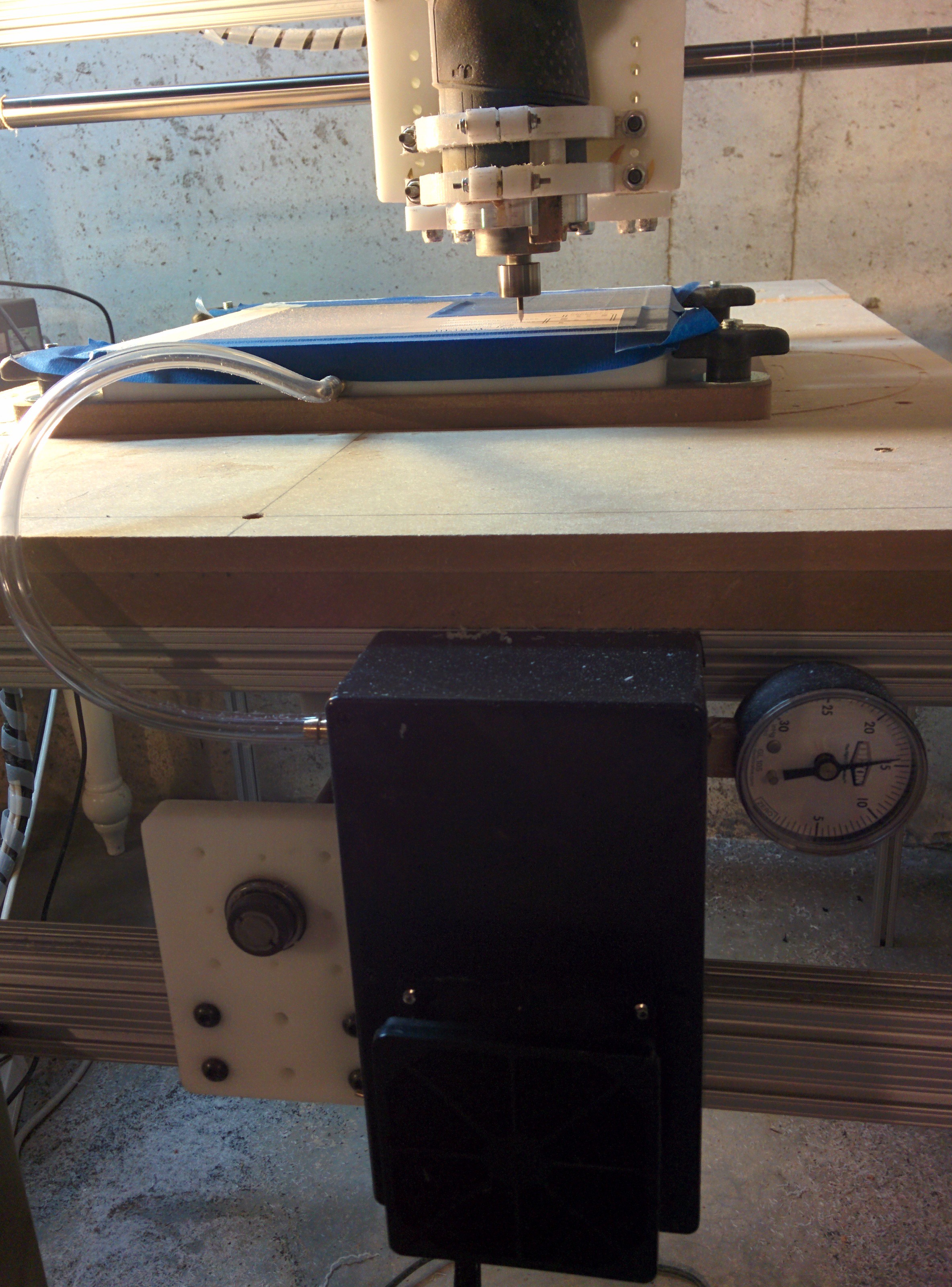
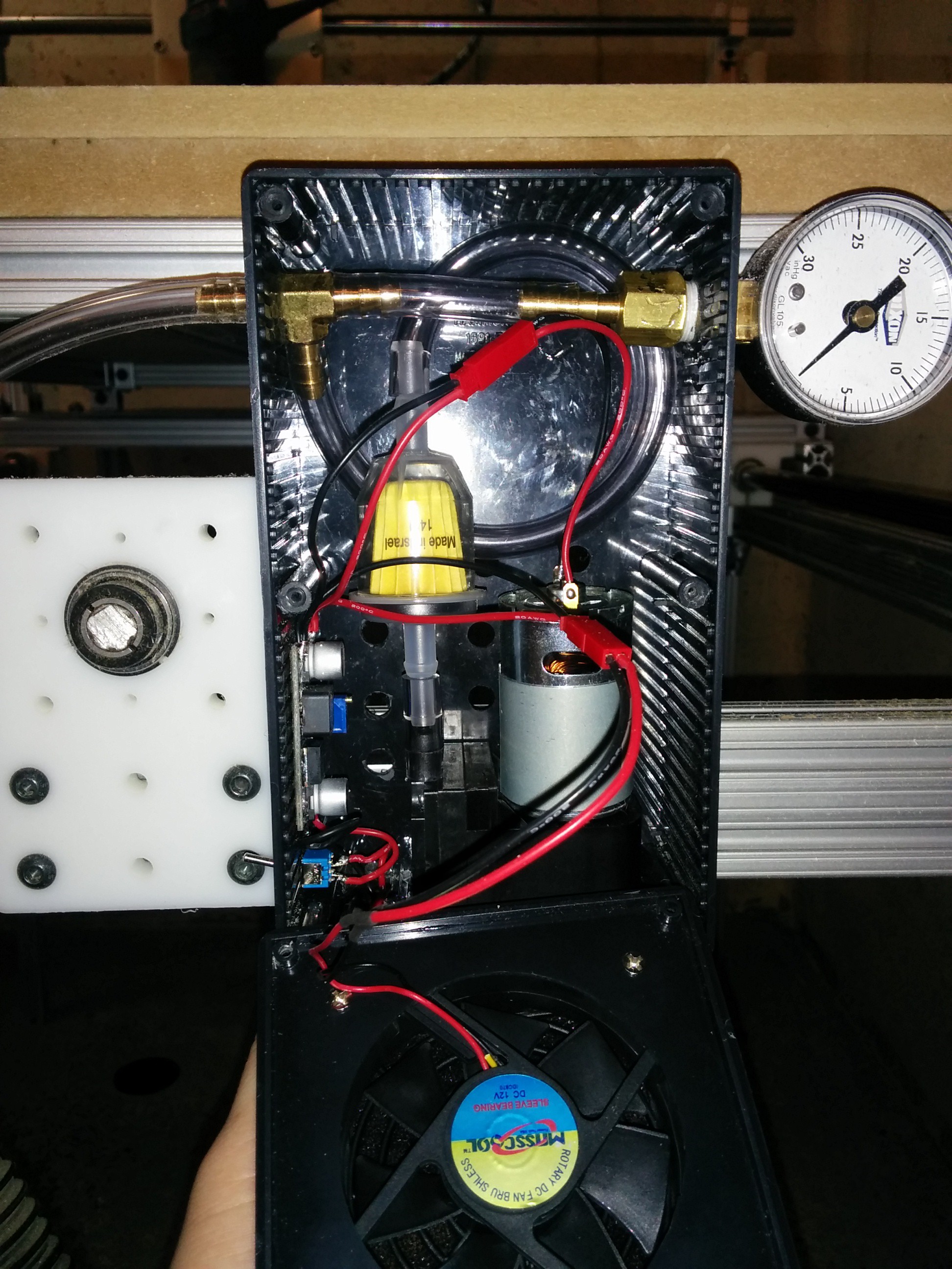
The vacuum pump is a simple 12v $15 pump available from sparkfun (https://www.sparkfun.com/products/10398) mine is capable of pulling 21" Hg of vacuum which is more than enough for my purposes. The vacuum is not intended to hold the board in place although it does. My goal with the vacuum table was to pull the warp out of the copper clad boards in order to give me a perfectly flat surface to machine. Inside the box is a fuel filter intended for a lawn tractor, it should filter out any dust or machining debris before reaching the pump.
Here is one of the finished boards.
And here is one that has been tinned and assembled. It's amazing what a mess of wires on a breadboard can become. I will say that soldering a circuit board without a solder mask is a little bit more difficult.
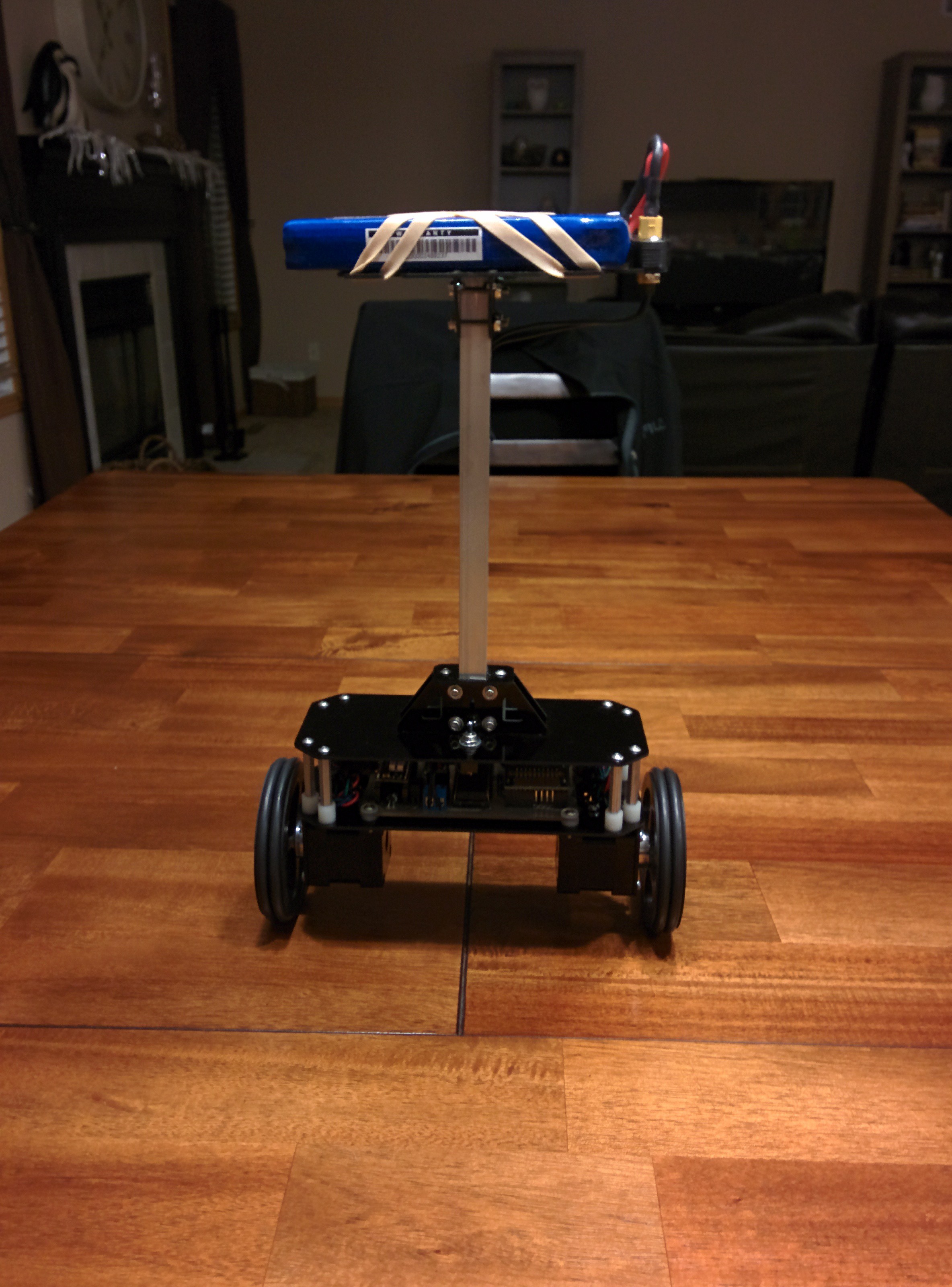
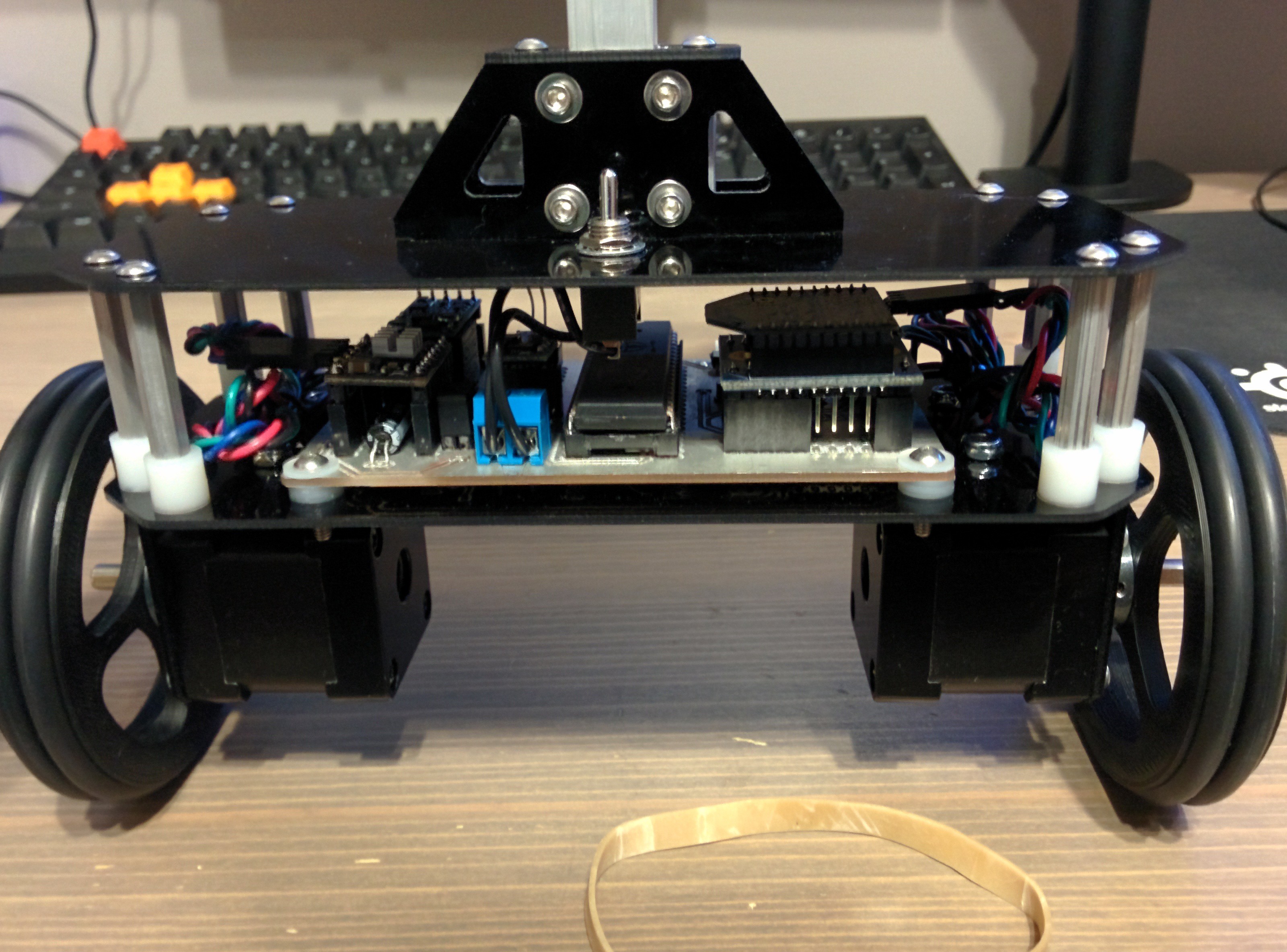
Bot Assembly:
This was the easiest part. The frame of the B-Bot is made from G10 cut on my CNC router. The mast is 1/2" aluminum square tubing.
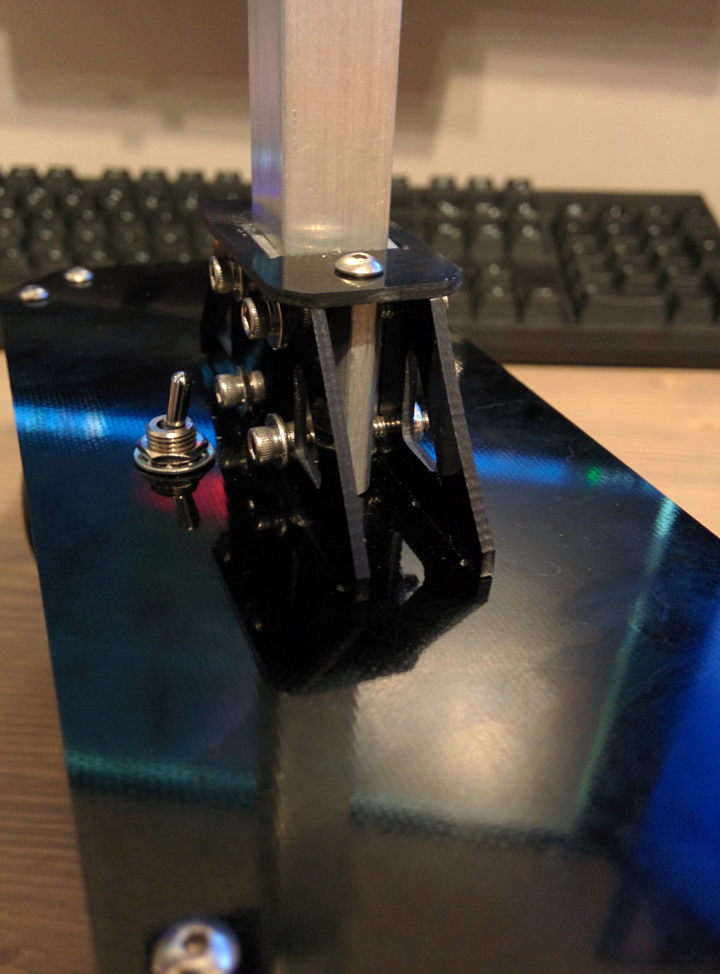
Here is the mast support. This is one of my standard methods for turning "2D" parts into a 3D structure. Tabs and slots clamped with aluminum standoffs. This creates a very stiff and robust joint.
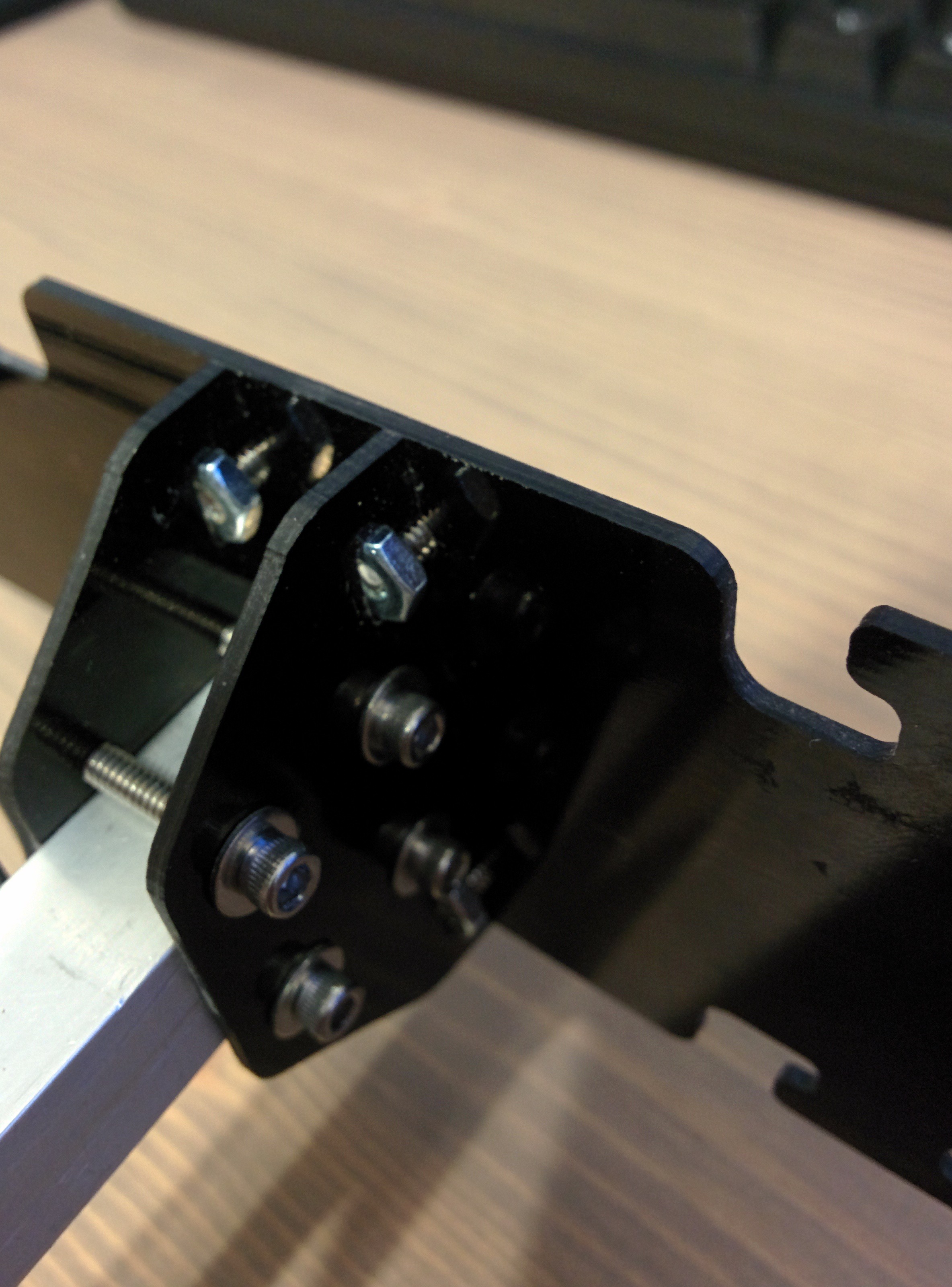
This is a joint I have seen in several other builder's projects but this is the first time I've used it. The tab has a cutout to fit a nut and the slot is drilled to accept a screw. It directly clamps the tab into the slot rather than indirectly like above. This is also a very sturdy joint and one that I plan to use more often.
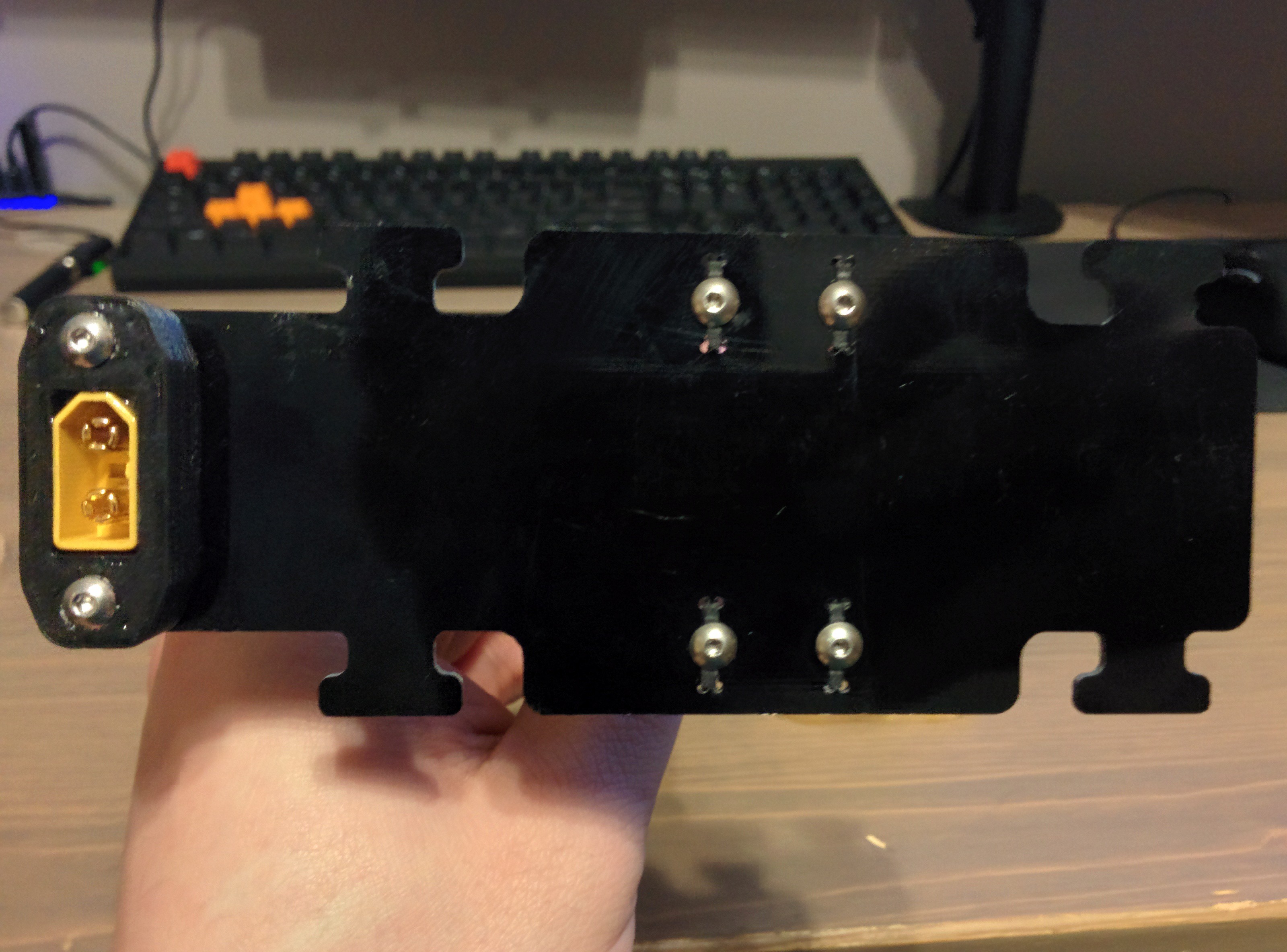
Battery holding plate with a 3D printed female XT60 plug holder. Simple T tabs for holding the battery in place with rubber bands.
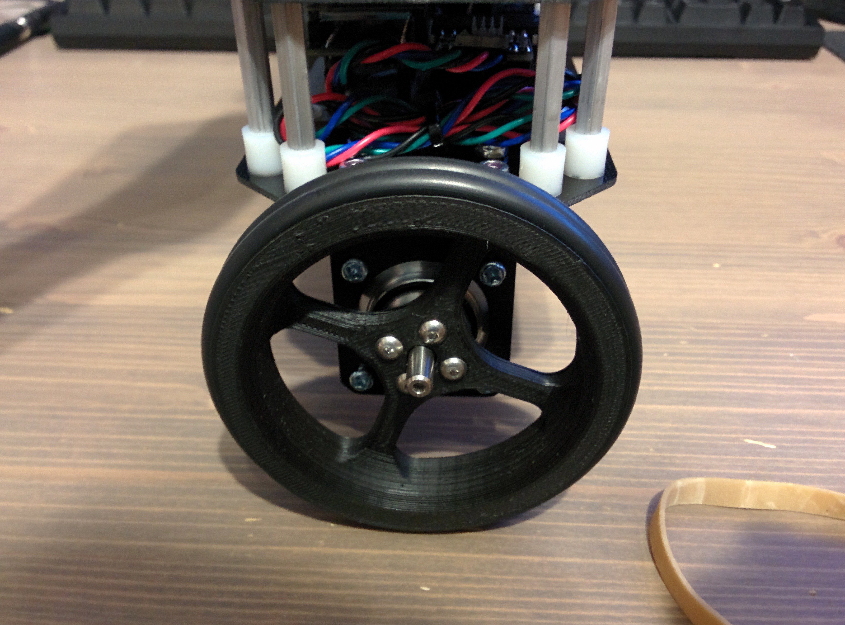
The wheels are 3D printed and use O-rings from discarded air filters as treads.
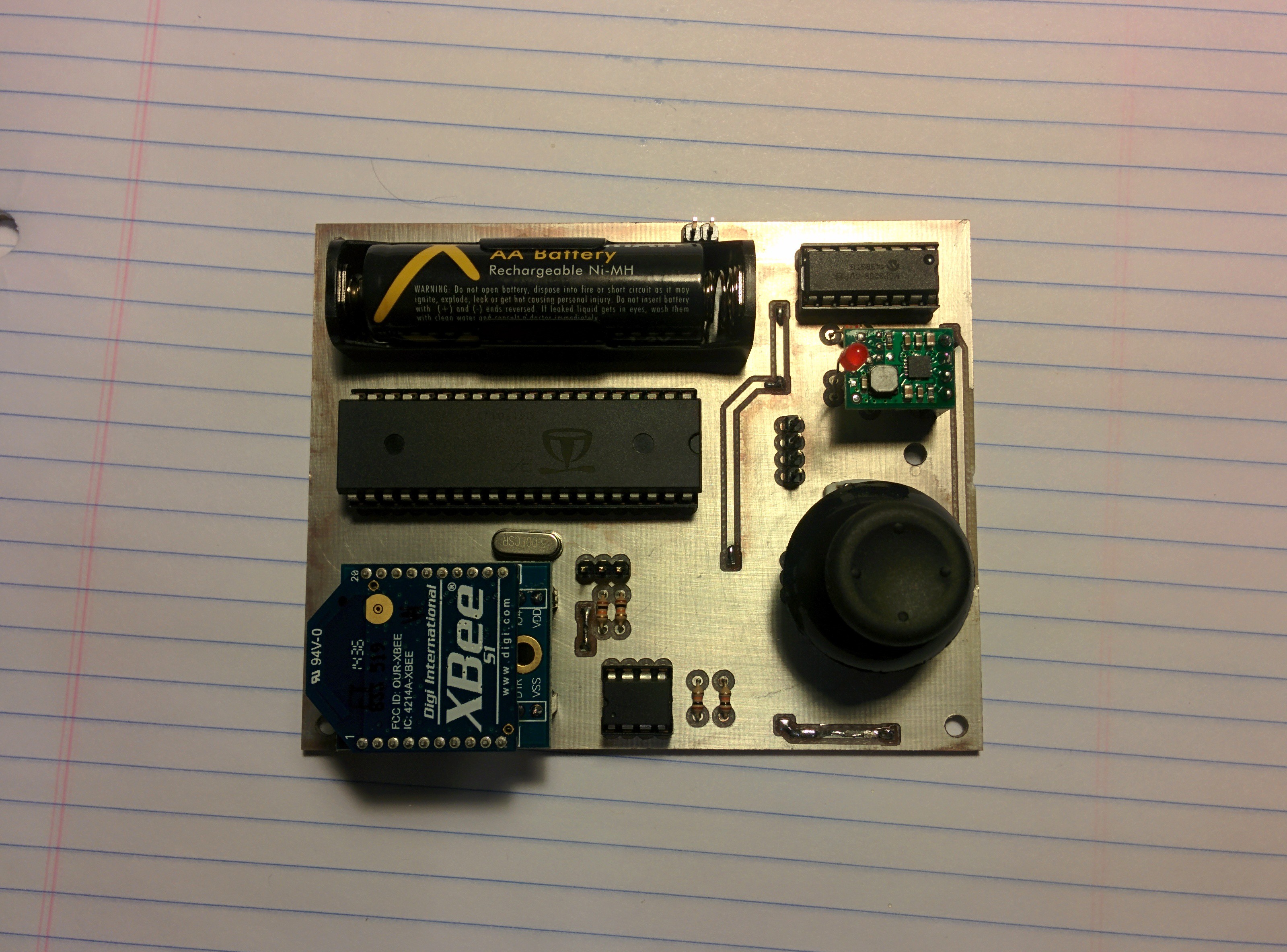
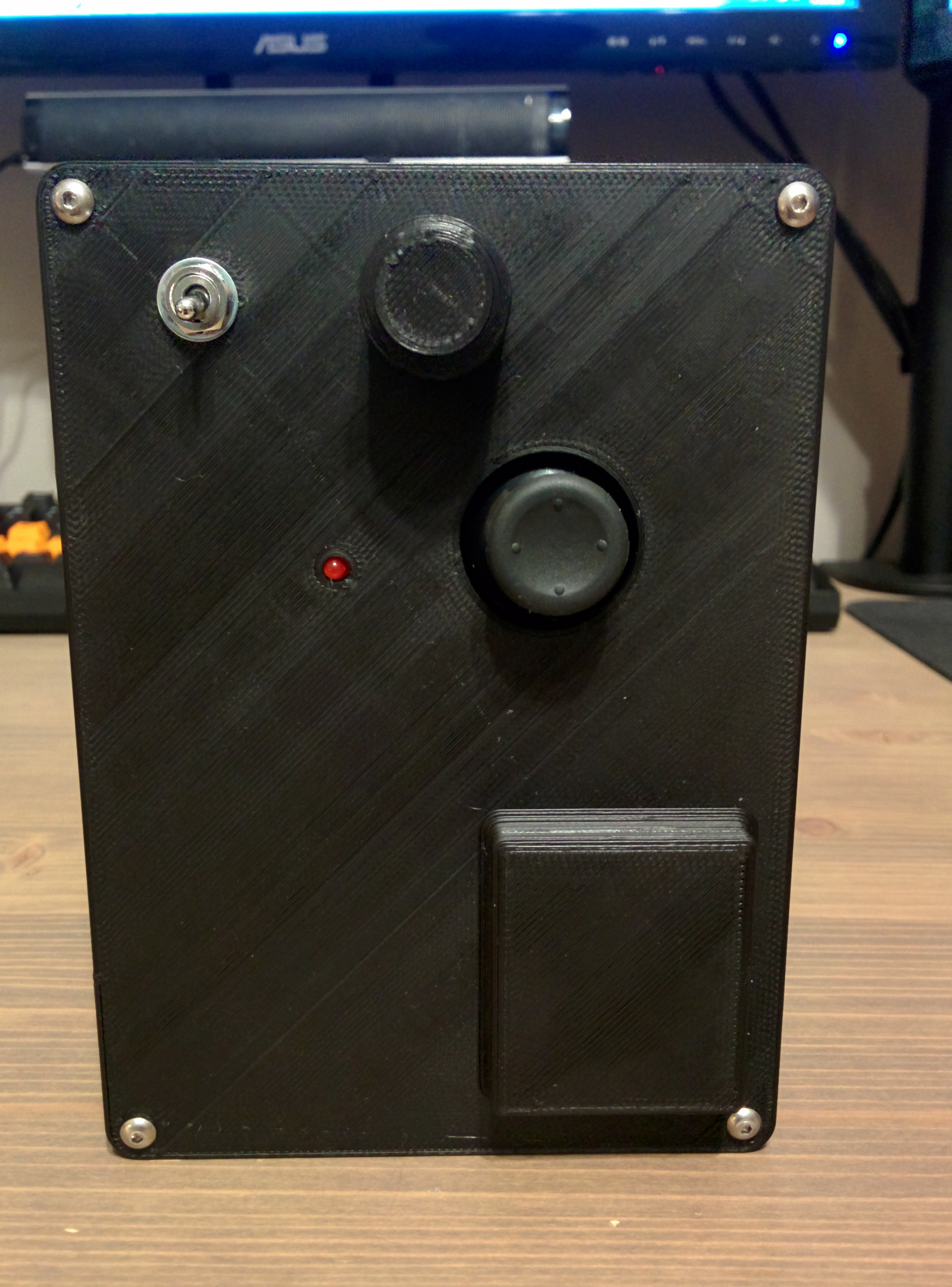
Controller:
The controller consists of an analog stick and an encoder. I originally thought I would need to trim the setpoint of the B-Bot after each startup but that turned out to be unnecessary. Differential type control. I had originally planned on the controller being much smaller but due to board size limitations of the freeware version of EagleCad it was not as small as I had hoped. It is powered by a single AA and boost converter. This was the first of the two circuit boards that I designed and I think it shows. I could have packed the components much tighter and made a smaller case. Maybe at another time.
Coding:
This is where the real frustration set in. I do not write a lot of code, it is messy and poorly commented. This is really the first project I have attempted that involves writing my own code. For those of you that may not know, the Prop is a multicore microprocessor. It has 8 cores called cogs. Each cog is capable of accessing all I/Os, they each have their own RAM buffer and are capable of accessing a global RAM for all cogs. The nice thing about the Prop is that it does not require the use of interrupts which is good for a novice coder. I can run the main PID loop on one cog, I2C communication on another, low pass filters on another, square wave generators on another, etc. However, the prop does not support native floating point math. A separate cog is configured to handle all floating point operations. This can get confusing because now you must keep track of what variables are floating and which are integers and they cannot be used in calculations together without conversion.
The main loop of the code gathers data from the sensors, combines and integrates the data to generate a current angle for the bot and then calculates error and motor inputs with PID control.
Gyroscopic drift is handled with a simple complementary filter. The accelerometer data is incredibly noisy and is tamed using a moving average filter. The stepper motors are controlled using square wave generators. By using signal generators rather than standard stepper driver code I can control motor velocity simply by setting output frequency rather than having to account for and time each motor pulse. The output frequency of the stepper motors is also filtered using a moving average to reduce motor induced vibration noise.
PID tuning is difficult to say the least. I understand how each term compensates for error but figuring out what each gain should be set to is a frustrating endeavor. I've currently used a Zeigler-Nichols approach, and while it has given me a starting point, I still have much tuning to do. The B-Bot will balance and turn in place, it will recover from being pushed but suffers from excessive overshoot upon returning to normal and does not stay in one spot as tightly as I would like.
Aside from the PID tuning the last hurdle I must overcome is accomplishing reliable constant velocity forward and reverse motion. Believe it or not this is actually a fairly difficult problem. I've tried simply adding steps to each motor output on top of the PID output but the controller simply responds as a step input and stays still.
I've had some success by varying the angle setpoint. The B-Bot will move forward and backwards when I change the setpoint but changing the angle setpoint results in the B-Bot trying to achieve a constant forward or backward acceleration rather than a constant velocity and the PID still tries to fight the control inputs. When the bot tries to achieve a non zero tilt angle it must continuously accelerate in order to avoid toppling.
Future:
For now I will be working on writing a routine for constant velocity forward motion. Perhaps I could run another PID loop that will strive for an average positive or negative motor step frequency by adjusting the tilt angle setpoint. If someone that has completed a balancing robot before has any insight on the constant velocity problem, PID tuning or anything in general I would love to hear from you.