 Duane Degn
This CNC router will be used to cut parts for my Health Maintenance Robot I'm building as part of the 2015 Hackaday Prize (there wasn't an option to add this link in the description).
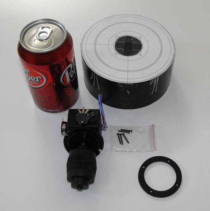
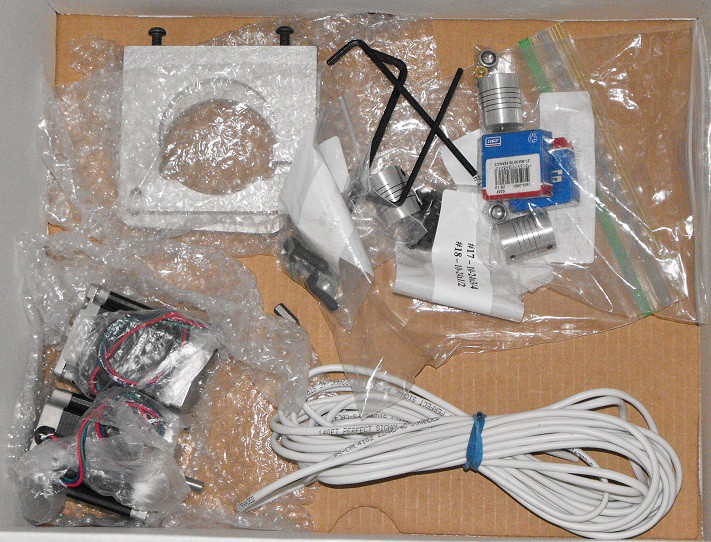
The controller has two Propeller microcontrollers. One Propeller acts as a graphics slave (and keypad reader). The other Propeller will generate the direction and step pulses to drive the stepper motors.
While I may eventually purchase a PC and software to use a "proper" controller, I want to try controlling the CNC router with a Propeller microcontroller first.
I'm hoping the controller will be able to read a SD card which will contain the desired tool paths. I would also like to be able to manually control the router with the attached 16 button keypad.
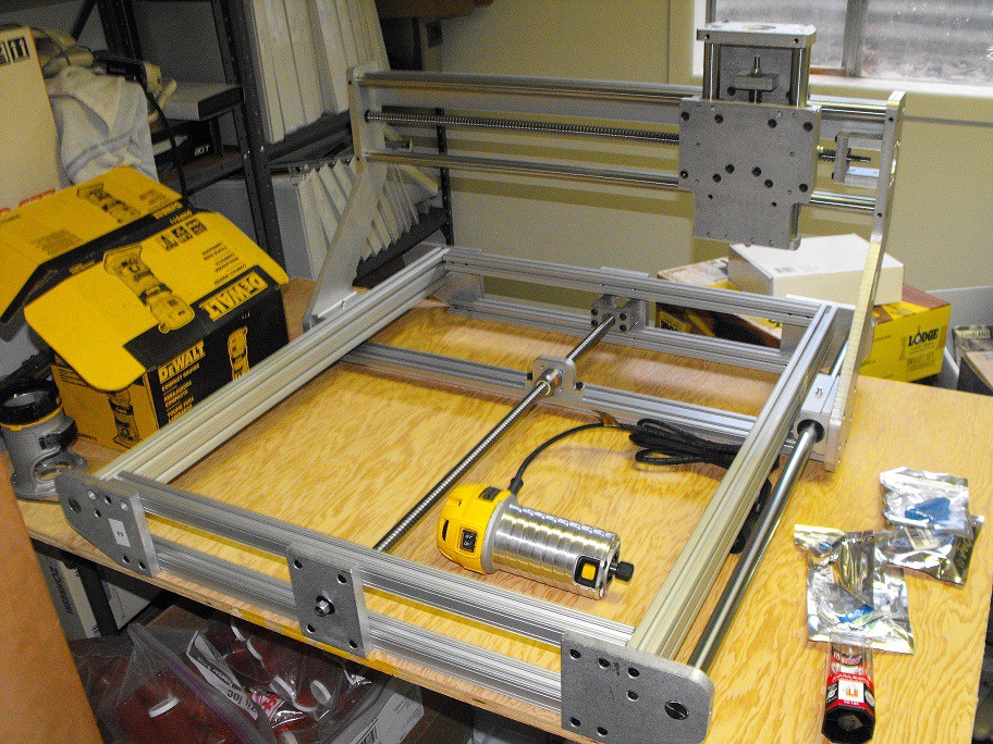
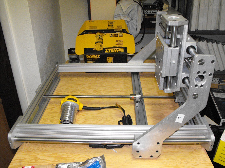
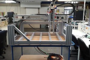
While most of this project will consist of programming the controller, I also need to finish putting together the CNC router.
I haven't taken photos of the router yet but I will likely do so within the next few days.


 Jeroen Delcour
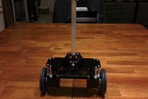

 Philip Zucker
I did the same project a few years ago. I had one propeller controlling a big XY table I made. My code would draw images based on text input of points, which was kind of cumbersome. Are you by any chance using different cogs to control the X and Y motors simultaneously? I tried to get that to work to see if I could get smoother movements, but I had trouble synchronizing them, so I ended up implementing the motor control in a single cog.