 Idris
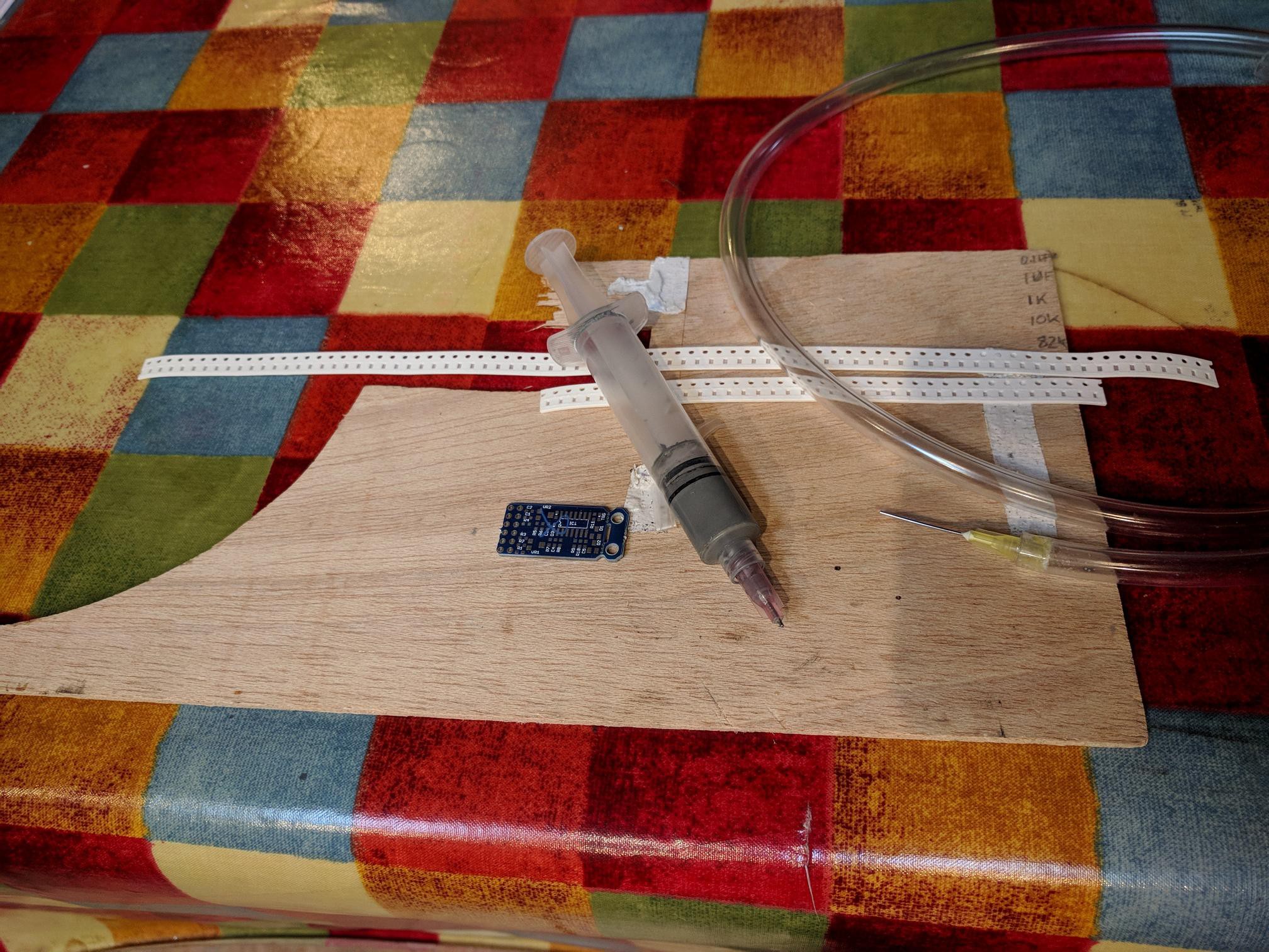
IdrisThe equipment used for assembling the first boards was as basic as it comes but I learned a lot. My intention in this project is to look at each of the tools I use to assemble PCBs and show how it's changed as I have gone from essentially a one-off batch of 12 to series production. We will be looking at, in no particular order;
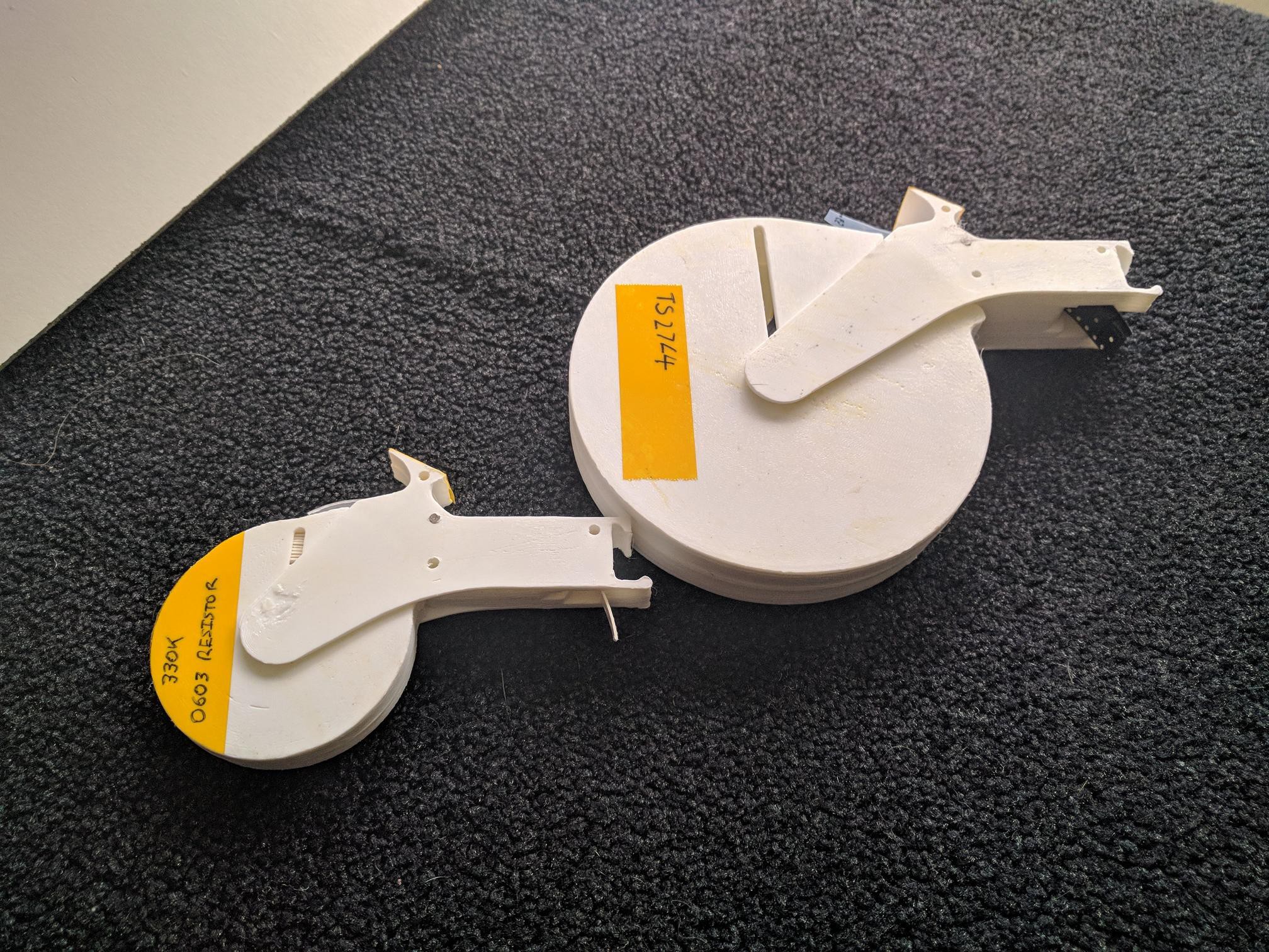
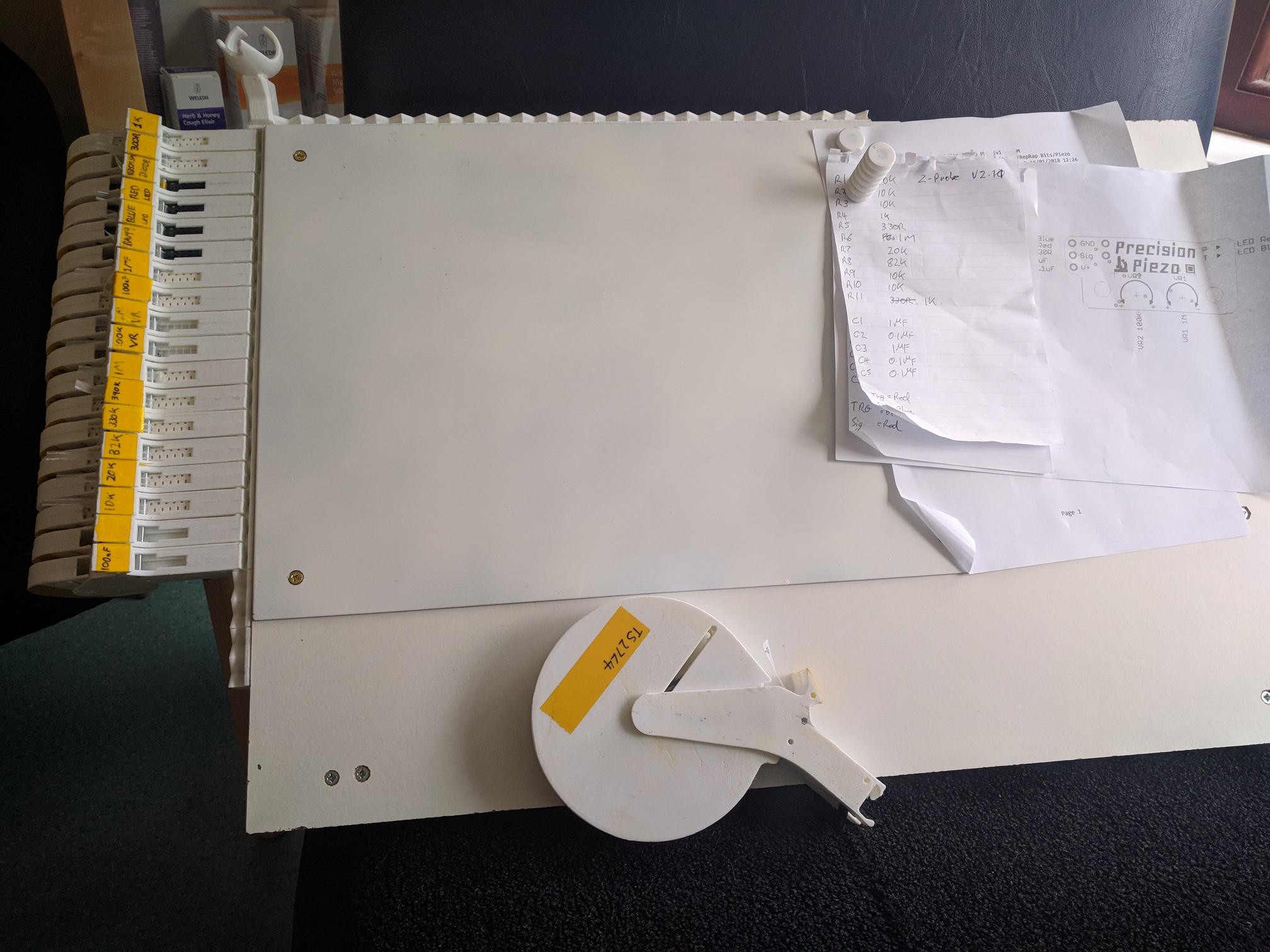
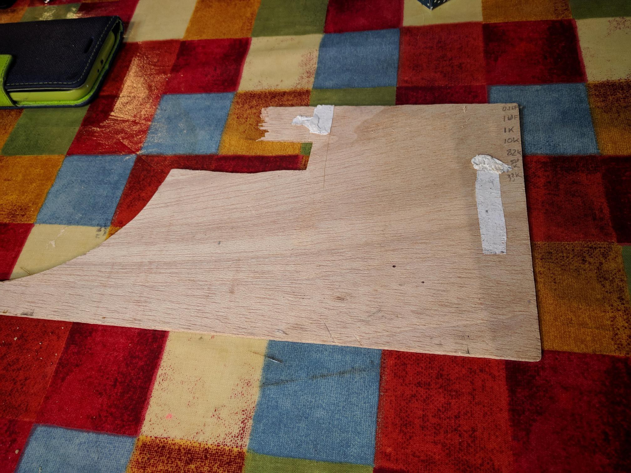
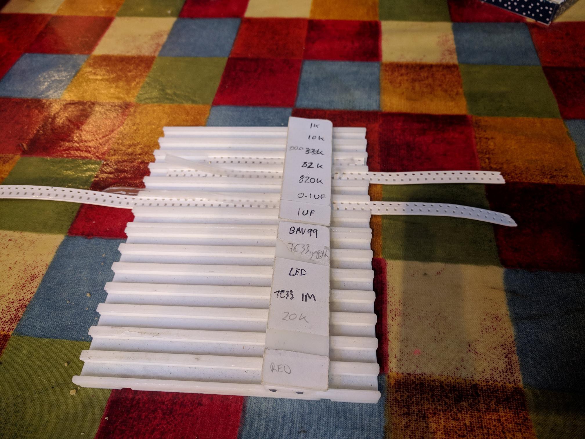
Component tape holding
Solder deposition
PCB holding
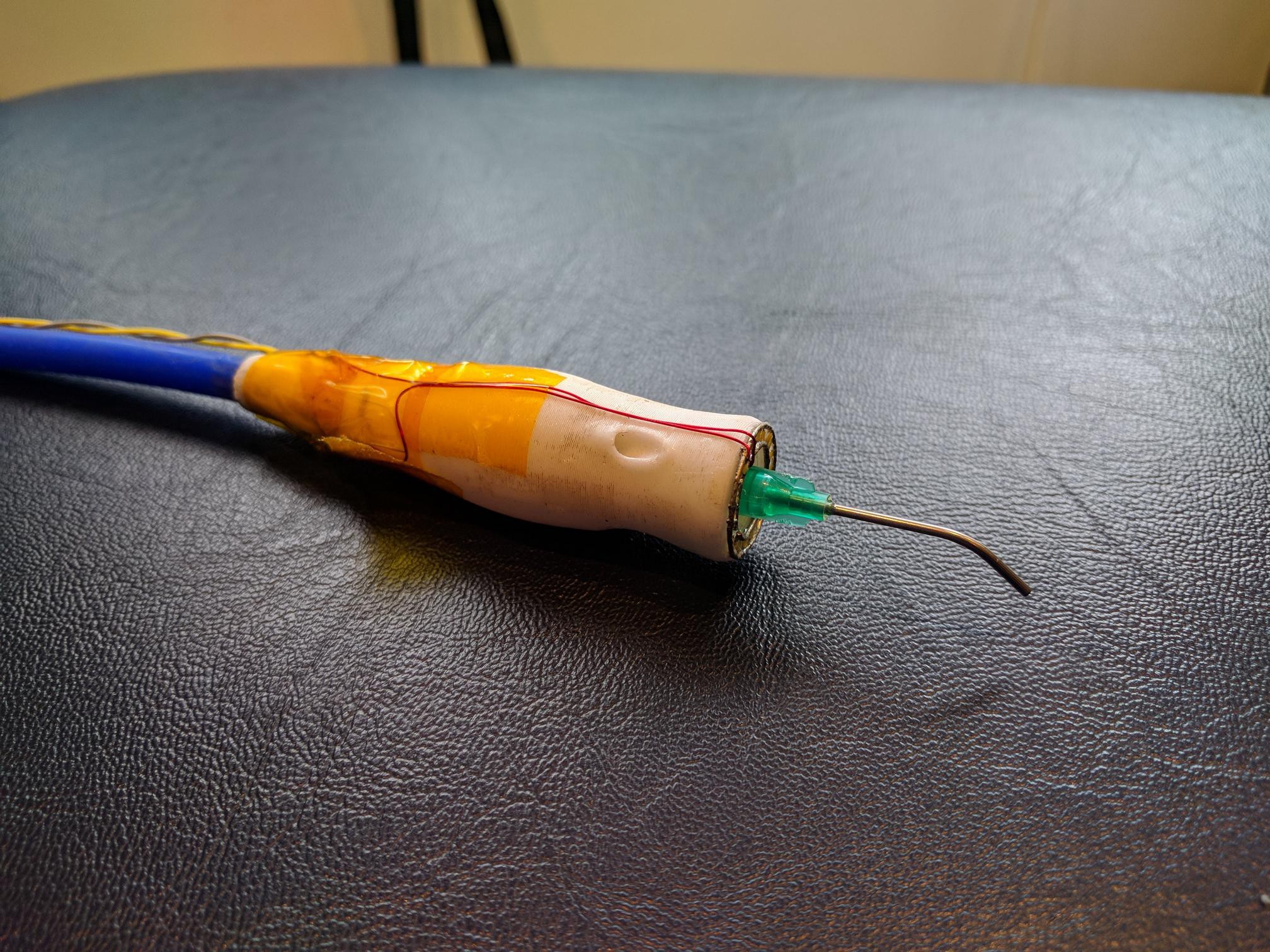
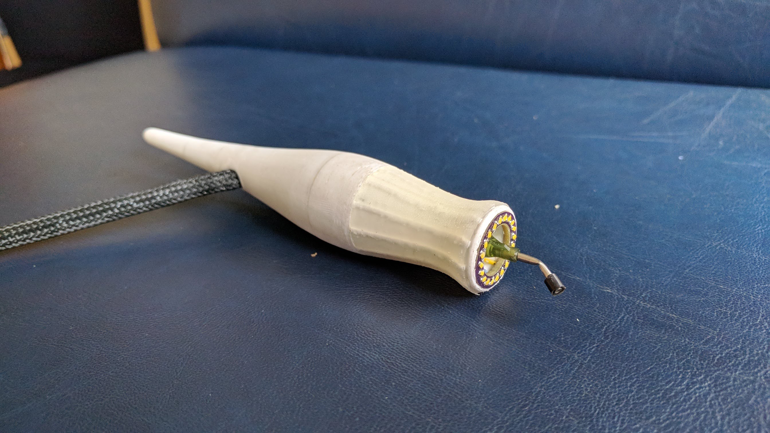
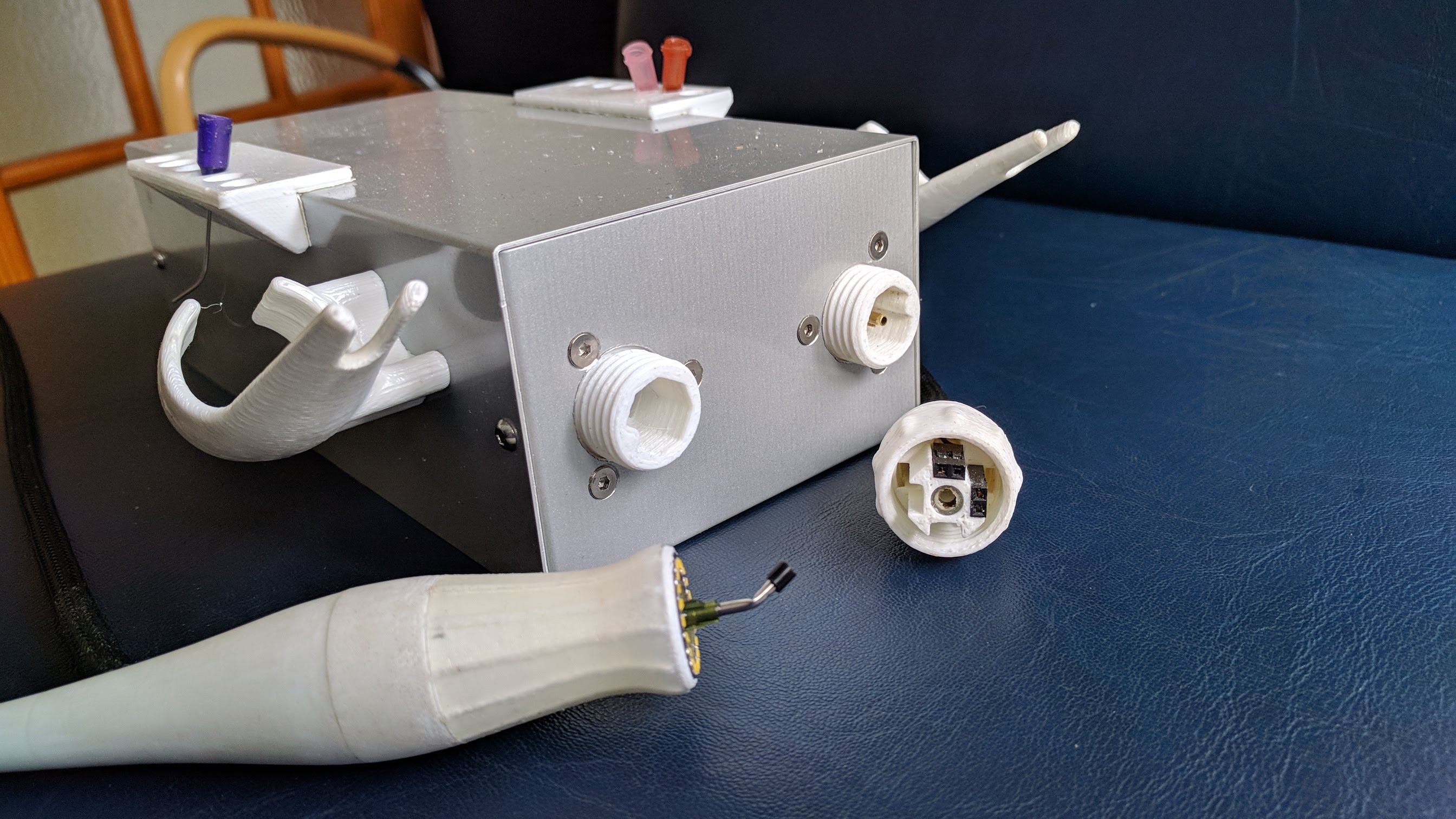
Component pickup
Reflow
Along the way I'll try to touch on the lessons I've learned regarding PCB layout for easy hand assembly.


 zittware
 Steve Dearden
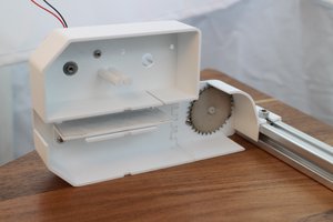
 ottoragam
 Linus Dillon
love the vacuum pickup design! the handheld portion is really nice! i'd like to see about adapting that to my vacuum pickup design - https://hackaday.io/project/19189-diy-vacuum-pickup-tool