 Radu Motisan
Designing the wifi interface using the ESP8266 was not easy as I ran into several problems costing me precious time. I got a few esp8266 modules back in 2014, shortly after they've been announced on HackaDay. I didn't have much time for them, being caught with other projects, up until recently when the portable environmental monitor project needed a versatile wireless communication mechanism, low powered and if possible at a decent price. The esp8266 seemed the best candidate, but like with everything in life where nothing comes free, getting it going was not that simple. Here's an article with things that helped me do some ESP8266 Troubleshooting.
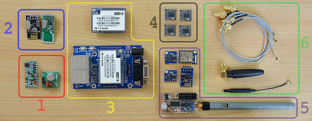
The pictures shows:
1.FS1000A / XY-FST Radio module
2.NRF24L01 transceivers
3.HLK-RM04 UART Wifi module and test base board
4.Realtek RTL8188 Wifi modules
5.Various ESP8266 modules 5.SMA cables and antennas
I had to opt-out the low level radio modules, the FS1000A and the NRF24L01 because I needed to follow a standard that would make connecting my devices easier. By using any Wifi 802.11X compatible module, the portable environmental monitor can be connected to any home internet access point, without additional hardware. Being left with 3 choices, I went for the ESP8266 because its low cost and popularity. Both the ESP8266 and the HLK-RM04 are full stack wifi modules, but the latter is larger and my PCB space was limited. The RTL8188 only contains the MAC and the PHY, so this complicates the software; it also uses an USB interface, incompatible with my current microcontroller choice, the atmega128.
There are several types of ESP8266 modules. Those in my toolbox included the ESP-01, ESP-02, ESP-04, ESP-05 and ESP-07. For my project I needed an all-SMD module with exposed antenna pin instead of the small IPEX connector, so I can use my own SMA antenna connector. The ESP-04 fits all these requirements, still for a first test I went with the ESP-01 due to its breadboard friendly pins. My plan was simple, hook it to the 3.3V powered atmega128 board UART pins and write some simple serial communication code (send AT\r\n etc).
The esp8266 ESP-01 I had was configured for 115200bps. The ESP-04 and the ESP-05 were both set to 9600bps. These baudrates can vary depending on the firmware, but 9600 and 115200 are the two common values.
At first I had little luck getting the atmega128 to communicate with the Wifi module, due to some errors in my code. It is just a simple UART communication, nothing fancy, but the 115200 value overflown the integer limit of my baudrate variable. This got me hooking the ESP8266 module directly to my computer via a FT232 USB to UART module, modified for 3.3V. The FT232 must make common ground with the ESP8266. Under MacOS I used both the screen terminal command and the CoolTerm app to communicate with the modules.
The UART0 was connected to the ESP8266 and communication displayed on the ILI9341. UART1 was connected to the computer, via a FT232 module to sniff the traffic.
Things that didn't work at first:
- integer baudrate variable was too small for the 115200 value, resulting in wrong baudrate setting, and weird output characters
- sent AT commands if not terminated in \r\n just returned an echo instead of doing their job.
- for all modules other than the ESP-01, the GPIO15 must be grounded, or strange characters will appear
- the CH_PD must be pulled high (connected to Vcc)Custom test board
To make testing easier I also built a nice USB to Wifi module, to push my soldering skills to the limit but also see how well I can design a working board with the FT232RL, the ESP-04 and a SMA antenna connector.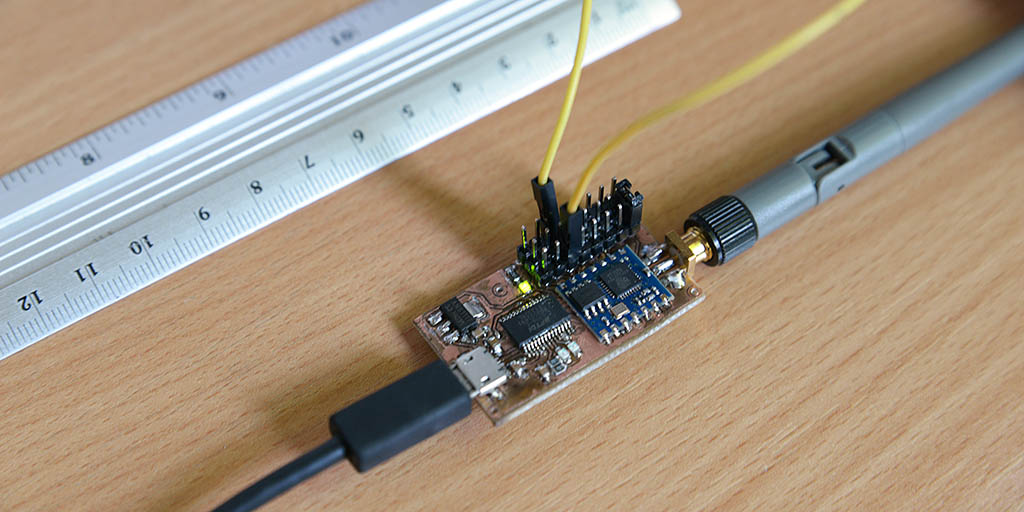
It came out nice, and proved to be very useful for testing the ESP8266 AT commands before designing a parser to run on a microcontroller.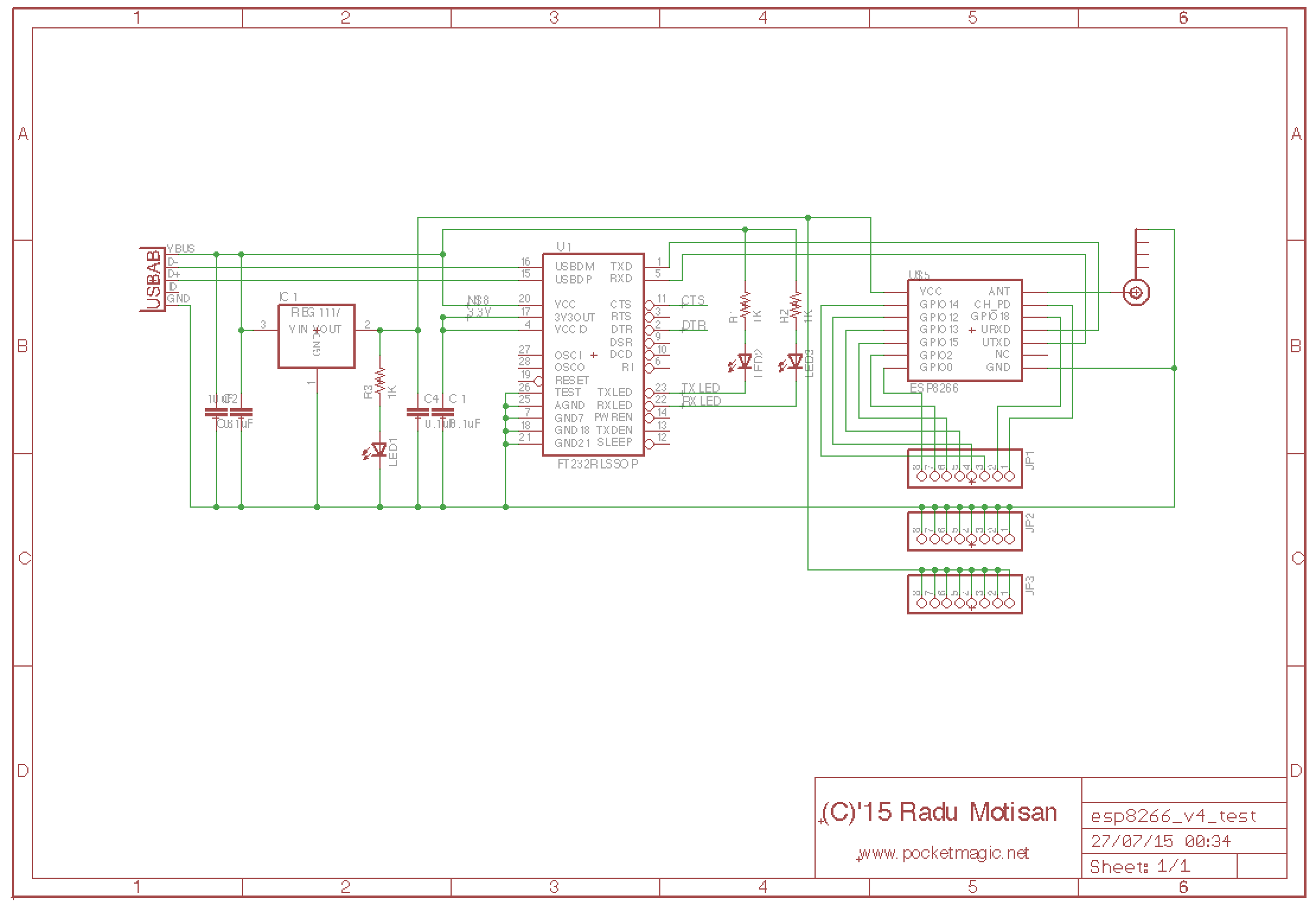
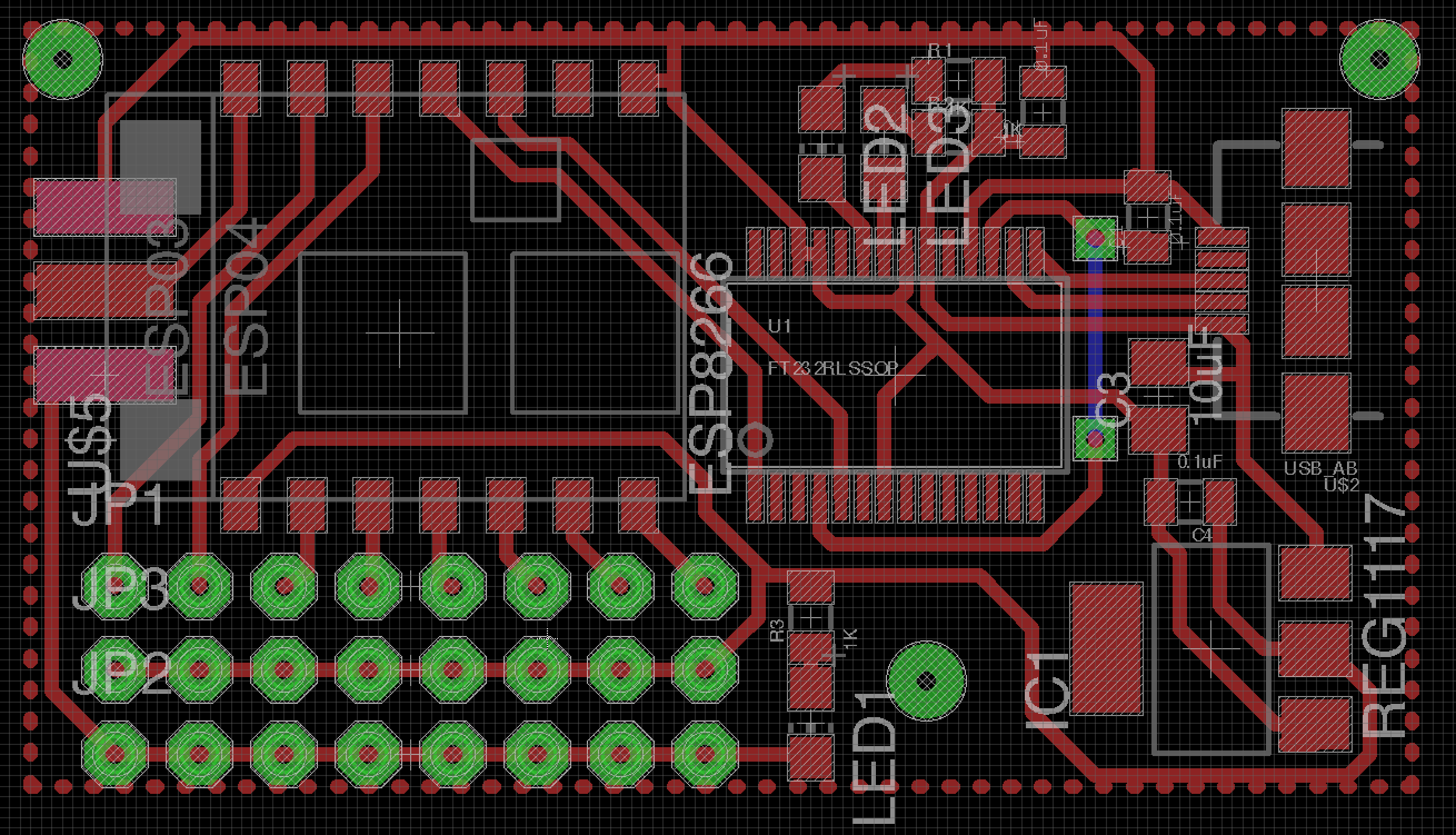

Eagle design files are available here: http://www.pocketmagic.net/esp8266-troubleshooting/
Discussions
Become a Hackaday.io Member
Create an account to leave a comment. Already have an account? Log In.