Bruce Land
I decided to start by implementing Butterworth IIR filters using the fixed point formats below. The first step is to find out how much the limited precision arithmetic will affect the filters. I am not using the PIC32 DSP ligrary because I could not figure out the format for the constants. Filters are implemented as unfactored first or second order Direct forms or as second order sections (SOS) which take a scale factor input as well as two a-vector values. For Butterworth, the b-vector is fixed (refer to Matlab or Octave butter function). This matlab program allows you to check SOS filter response accuracy for a given bandwidth. This program uses an unfactored IIR filter design for comparision. For low-order filters (one or two samples), unfactored IIR filters will be faster, while being accurate enough.
-- A one-sample (RC type) lowpass filter executes in 89 cycles on the PIC32 as shown in this C program. The filter uses an array for the filter coefficients and another for the filter history. Inserting this filter into the ADC-to-DAC code in a section below results in a program in which the ISR samples the ADC, filters, scales and outputs to the DAC in 2.7 microseconds, including ISR overhead (60 MHz core clock). In this code, the sample rate Fs=100 kHz, the filter cutoff is 0.01/(Fs/2)=500 Hz. Actual cutoff measured in 490 Hz. This filter has less than 1% error above a cutoff=0.002.
// coeff = {b2, -a2} noting that b1=b2 and a1=1 (for first order Butterworth) // history = { last_input, last_output} fix16 coeff[2], history[2], output, input ; fix16 IIR_butter_1_16(fix16 input, fix16 *coeff, fix16 *history ) { fix16 output; output = multfix16(input+history[0], coeff[0]) + multfix16(history[1], coeff[1]) ; history[0] = input ; history[1] = output ; return output ; } -- A second order Butterworth lowpass has less than 1% response error down to cutoff=0.04. At cutoff=0.1 (and Fs=100 kHz) the measured cutoff frequency is very close to 5 kHz, as predicted. The ISR takes 3.5 microSec to execute (60 MHz core clock). -- A second order Butterworth bandpass can be set down to a bandwidth of about 0.003 with less than 1% error. At cutoff=[0.1, 0.11] (and Fs=100 kHz) the measured peask response is 5.25 kHz and the cutoffs are at 4.98 and 5.5 kHz, as predicted. Tthe DC component of the input is removed by the highpass characteristic of the filter, so a DC correction has to be made because the DAC can only produce a positive voltage. In the ISR, 128 is added to the 8 bit DAC value
DAC_value = (output>>6) + 128 ;.-- A generalized SOS Butterworth lowpass executes in 7.5 microSec (ISR, 60 MHz core clock, 4-pole). The 4-pole version with a cutoff=0.1 has the predicted resopnses near the cutoff frequency and where the response drops to 0.1 of peak. Six-pole takes 10 microSec, 8-pole takes 12.5 microSec. The sample frequency is set to 20 kHz. This matlab program computes the filter parameters for SOS and prints C code to the matlab console window to paste into the program for both lowpass and bandpass filters.
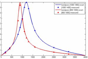
-- A generalized SOS Butterworth bandpass filter which uses the matlab progam mentioned just above to construct parameters. The example is set to a bandwidth of 0.002, about as narrow as you can get with 2.14 format fixed coefficients.
-- The SOS filters above are easy to read, but slow to execute because of the 2D arrays. Unrolling the loops, and making all the indices constant, speeds up the filters by almost a factor of two. Thisprogram uses the UART interface to profile number of cycles to execute. Putting the revised SOS filters back into the realtime program with ADC and DAC gives an ISR time of 7.7 microSec for the 4-section, eight-pole, bandpass filter. Almost all of the time in the ISR is the filter. A reasonable rule would be 2 microSec/pole of filtering. At 8 kHz sample rate, could do about 60 poles of filtering, or about fifteen 4-pole filters.
 Ted Yapo