Close
0%
0%

Cube clock

A clock that uses 3 sides of a cube to display an analog clock.

Similar projects worth following
The plan is to create a cube with at least three sides consisting of LCD displays. The three displays will show the hands of a clock in such a way that from a certain angle the clock will look flat.
The other three faces of the cube will be either wood or 3D printed. The goal is to miniaturize the internal electronics far enough to later have the option of adding two or three extra displays, an accelerometer and/or gyros.
If at all possible I'd like to power the cube from an internal battery, but for starters an external power supply is okay.

I realize that this is all very ambitious for a relative amateur like me, so I'm hoping to find some support along the way.

Goals/plan:

1. Find and purchase main components as cheap as possible.

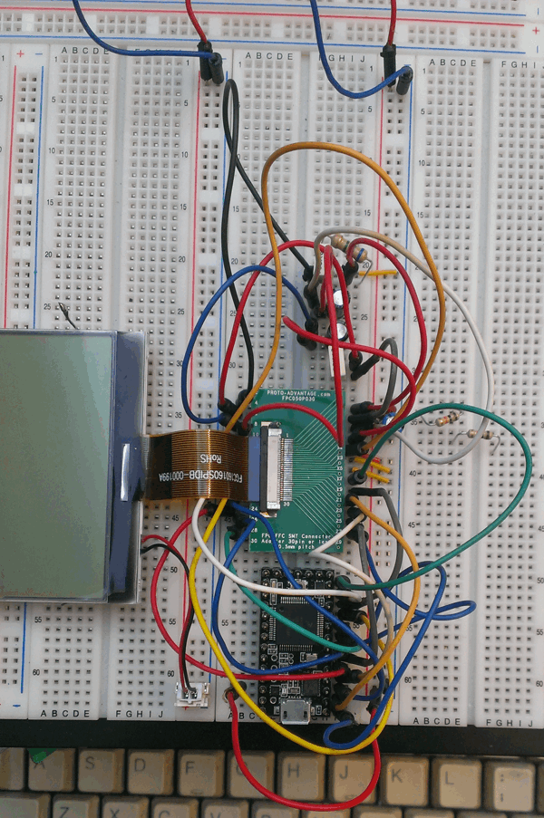
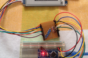
2. Hook a single display module up to a CPU on a breadboard.

3. Get the display to display something.

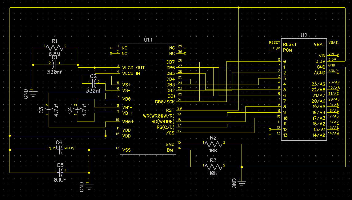
4. Write low-level library for addressing display.

5. Hook up two more displays and get them to work as well.

6. Write software to translate time to skewed 3D display.

7. Design a PCB to combine it all while still fitting inside.

8.  Combine everything together into a working cube clock.

9. Optionally extend with gyro/acc sensors.

Datasheets for LCD modules:

ERC160160-2 Series Manual

Controller UC1698 Data Sheet

ERC160160-2 Series Interfacing Drawing

Sample code:

ERC160160-2 Series Demo Code

  • 3 × 160x160 LCD module ERC160160FS-2 - 3 inch graphic 160x160 lcd display controller uc1698 module black on white
  • 1 × Teensy 3.0 USB-based microcontoller development system

  • Troubleshooting

    kender.arg03/23/2014 at 19:47 0 comments

    Okay, I still haven't gotten anything to display on the LCD.

    Probing with a scope shows that the communication between the teensy and the module looks alright.

    I even see voltages on some of the pins react proportional to the amount of pixels I'm allegedly writing to the screen. When the code was writing full black for a second and then full white for a second I could see the voltages on all the V lines go up or down with one second frequency. Changing the code to slowly ramp up and down the amount of pixels also shows gradually changing voltages.

    I'm just not seeing anything on the display itself.

    I also tried sweeping through the 0-255 range on the contrast register, and while this did show corresponding changes on the voltage pins, it did not show any change on the display itself.

    Just to be sure I swapped out the LCD module for another and get the exact same result.


    The datasheet page 32-34 seems to suggest that VLCD (pin 3 and 4) should be producing between 12 and 18 volts.

    I'm seeing between 1.7 and 2.4 volts on those pins.

    Unfortunately I'm running out of ideas on what could be going wrong. Does anyone have any suggestions?

  • So far

    kender.arg03/16/2014 at 10:19 0 comments

    I've got four EastRising LCD modules from www.buydisplay.com.

    I've got a Teensy 3.0 from Paul Stoffregen

    I've got a workspace stocked with all kinds of tools and components.

    The LCD modules comes with a FPC cable so I ordered some 30 Pins 0.50mm Pitch ZIF Connectors along with them. For prototyping I got a couple of FPC/FFC SMT Connector DIP adapters from  Proto Advantage.  These are awesome for breaking out a flexible cable to a breadboard.

    A quick EEVBlog SMD soldering tutorial later and I had the cable connected to a breadboard easily.

    I then breadboarded up what I think is a fairly accurate representation of the ERC160160-2 Series Interfacing Example Drawing 

    And a diptrace schematic of same.

    I've used the Teensy 3.0 rather than an 8080 MPU as used in the example.

    I'm also using the Teensy 3.3v output to power the display at the moment. I'm not yet sure about how I want to power the entire project later on. Battery? 5V wall-wart adapter with LM1117 conversion to 3.3v? Usb cable to Teensy?

    The single display (including backlight) already consumes 92mA so that could become a problem later.

    The display modules use the UC1698 driver chip, but unfortunately not all of its capabilities are available. Most unfortunate of which is that the SPI mode of the UC1698 is not available :(

    The pins (db13 & db15) needed to configure the driver for serial mode are not available on the cable. So the only choices left are the 8-bit 8080 or 6800 parallel modes. Which requires lots of pins (12) to address the display. The plan is to connect all the pins of all three displays together, except for the CS pins.

    Fortunately the Teensy 3,0 has plenty of pins available.

    I've also taken the ERC160160-2 Series Demo Code and ported the important bits:

    /*
    Quick & dirty port of main bits of demo code.
    */
    
    const int D0 = 0;
    const int D1 = 1;
    const int D2 = 2;
    const int D3 = 3;
    const int D4 = 4;
    const int D5 = 5;
    const int D6 = 6;
    const int D7 = 7;
    
    const int WR1 = 8;
    const int WR0 = 9;
    const int CS0 = 10;
    const int CD = 11;
    
    void setup()
    {
      Serial.begin(9600); 
      delay(1000);
      Serial.println("Setup"); 
    
      pinMode(D0, OUTPUT);
      pinMode(D1, OUTPUT);
      pinMode(D2, OUTPUT);
      pinMode(D3, OUTPUT);
      pinMode(D4, OUTPUT);
      pinMode(D5, OUTPUT);
      pinMode(D6, OUTPUT);
      pinMode(D7, OUTPUT);
    
      pinMode(WR1, OUTPUT);
      pinMode(WR0, OUTPUT);
      pinMode(CS0, OUTPUT);
      pinMode(CD, OUTPUT);
      
      init();
    }
    
    void output(uint cl) 
    {
      digitalWriteFast(WR1, HIGH);
      digitalWriteFast(WR0, LOW);
      ((cl & 0x01)) ? digitalWriteFast(D0, HIGH) : digitalWriteFast(D0, LOW);
      ((cl & 0x02)) ? digitalWriteFast(D1, HIGH) : digitalWriteFast(D1, LOW);
      ((cl & 0x04)) ? digitalWriteFast(D2, HIGH) : digitalWriteFast(D2, LOW);
      ((cl & 0x08)) ? digitalWriteFast(D3, HIGH) : digitalWriteFast(D3, LOW);
      ((cl & 0x10)) ? digitalWriteFast(D4, HIGH) : digitalWriteFast(D4, LOW);
      ((cl & 0x20)) ? digitalWriteFast(D5, HIGH) : digitalWriteFast(D5, LOW);
      ((cl & 0x40)) ? digitalWriteFast(D6, HIGH) : digitalWriteFast(D6, LOW);
      ((cl & 0x80)) ? digitalWriteFast(D7, HIGH) : digitalWriteFast(D7, LOW);
      digitalWriteFast(WR0, HIGH);
    }  
    
    void write_com(uint para)
    {
      Serial.print("Command: "); 
      Serial.println(para, HEX); 
      digitalWriteFast(CS0, LOW);
      digitalWriteFast(CD, LOW);
      output(para);
      digitalWriteFast(CS0, HIGH);
    }
    
    void write_data(uint para)
    {
      digitalWriteFast(CS0, LOW);
      digitalWriteFast(CD, HIGH);
      output(para);
      digitalWriteFast(CS0, HIGH); 
    }
    
    void init()             
    {        
      delay(200);
      write_com(0xe2); // set system reset
      delay(100);  //delayms 200ms
      
      /*power control*/					
      write_com(0xe9);			//Bias Ratio:1/10 bias
     write_com(0x2b);			//power control set as internal...
    Read more »

View all 2 project logs

Enjoy this project?

Share

Discussions

beat wrote 07/17/2016 at 11:07 point

Hi kinder.arg
Do you have some updates of this project? I know it's been a while, but I have similar problems with my LCD displays which I want to bring alive for working.
Thank you!

  Are you sure? yes | no

kender.arg wrote 07/24/2016 at 05:58 point

Sorry no. I hit a dead end and have been doing other things since then.

  Are you sure? yes | no

Mike Szczys wrote 03/17/2014 at 03:38 point
Very awesome, the concept is really nice.

I'm wondering about the math to plot shapes on three screens that are not on the same plane. Do you have experience with this?

Reminds me of calculating wireframe model animation. Somehow in reverse?

  Are you sure? yes | no

kender.arg wrote 03/20/2014 at 20:01 point
Thank you.
I must confess that I haven't planned it all out to that level of detail yet.
I'm going to just take it a step at a time and figure out how to get to the end result along the way.

I do have some 3d wireframing experience in C#, but doing it on bare metal is indeed going to be a challenge on its own.

  Are you sure? yes | no

RodolpheH wrote 03/16/2014 at 10:29 point
Hi, I'm curious about your project. Can you provide us pictures of your installation ? It's hard to realise how it looks like.

  Are you sure? yes | no

kender.arg wrote 03/16/2014 at 11:21 point
Heh, I was just taking pictures when you wrote that.
Pictures are with the backlight off and the one with the clock is obviously edited.

  Are you sure? yes | no

Similar Projects

Does this project spark your interest?

Become a member to follow this project and never miss any updates