Current software supports all of the features in the description. Additions include adding the ability to set the RTC based on the Rubidium PPS signal during long GPS outages. Also want to add a basic menu system to support options like animation style of digits, brightness setting, GPS in/out, time zone, rotating display mode (e.g. date, time, other info).
Front panel will have main power switch and Rubidium power switch--this will support fanless operation without the Rubidum source being powered up. This will give it very low-power consumption in non-atomic mode (and lets be honest, will sacrifice essentially nothing in accuracy as long as GPS is switched in).
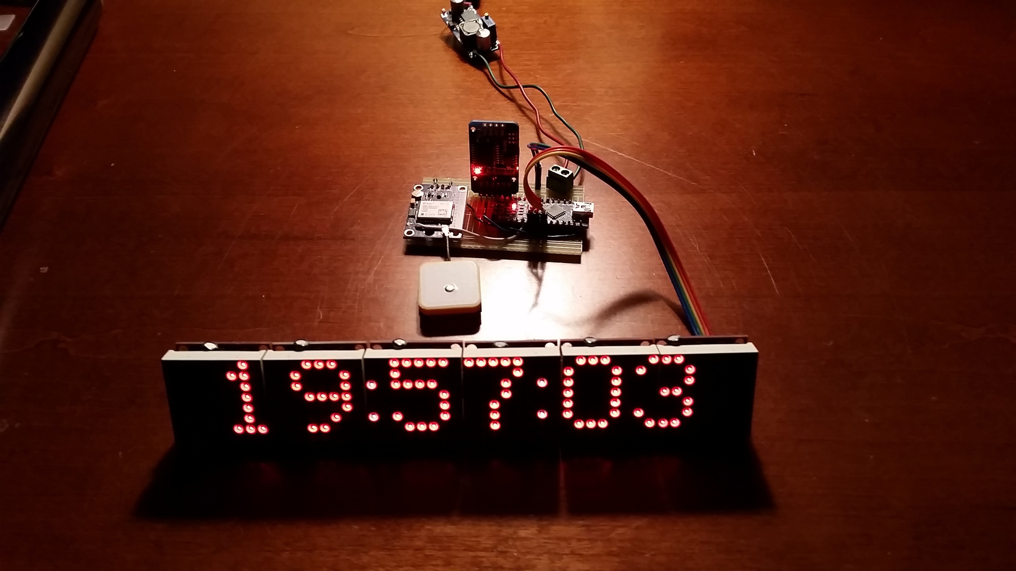
Using the Matrix library to drive the 8x8 LED panels, but had to modify to rotate pixels 90 degrees due to the way they are mounted on the PCB. Will use right-most column of display to indicate statuses and signals: GPS PPS, Rubidium PPS, RTC PPS, internal clock "tick" and Rubidium lock.
The display matrices are now soldered together and ready to mount behind the glass:
Front panel is complete:
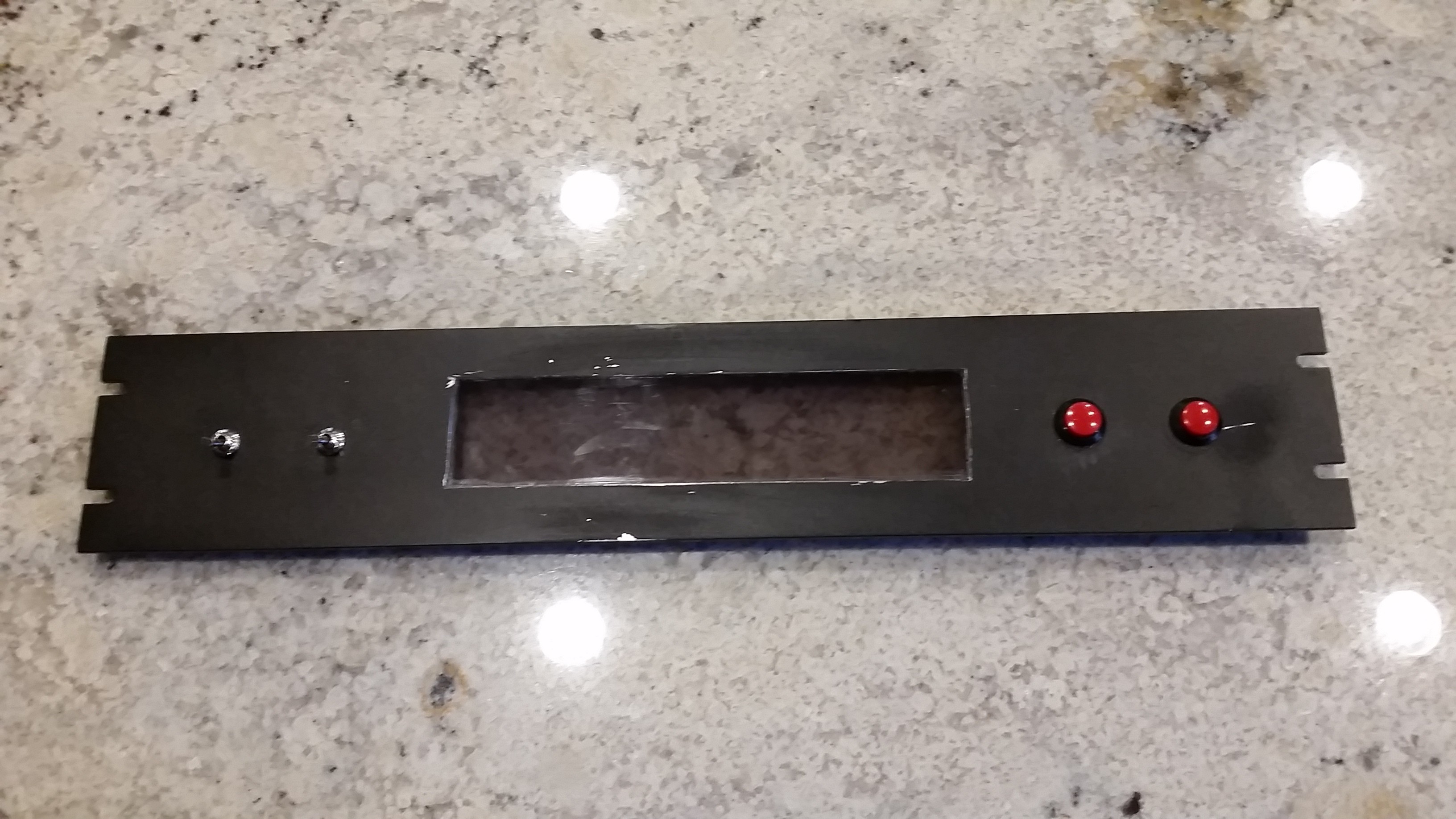
Just need to mount stuff inside and tidy up the wiring.
Using a Kill-a-Watt, this clock consumes about 9 watts in atomic mode and under 3 watts with the Rubidium source switched off.

 K.C. Lee
 Pierre-Loup M.
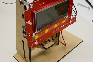
 Dave Ehnebuske
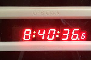
 Nick Sayer
Are you going to publish the wiring diagrams and software that was used such as the Arduino sketches?