 Andre Maia Chagas
The setup is quite simple:
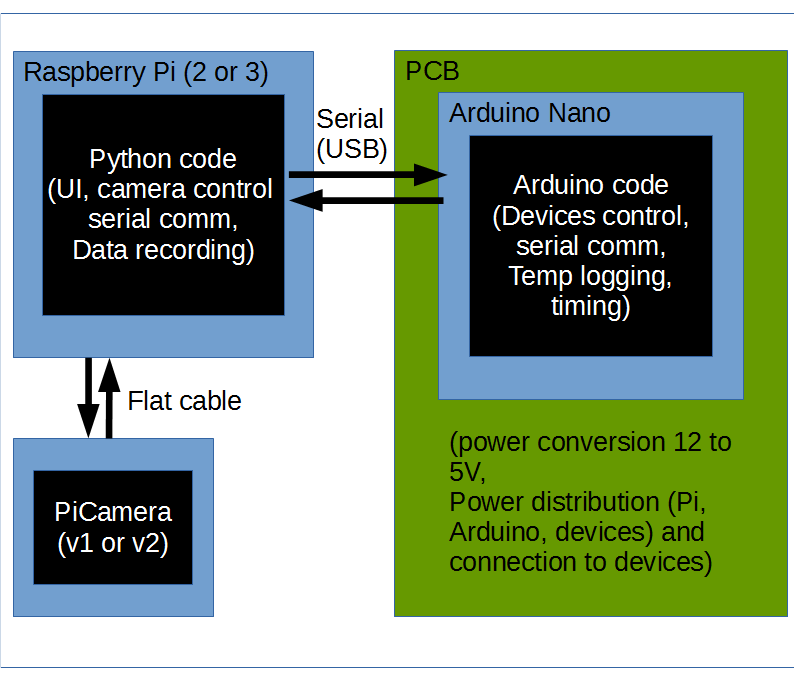
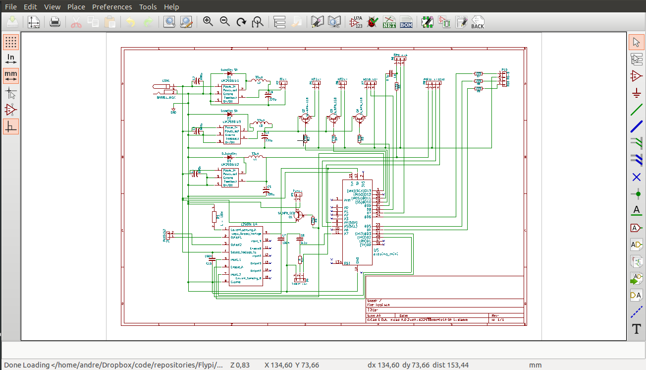
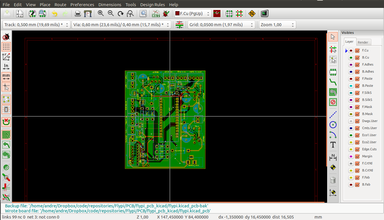
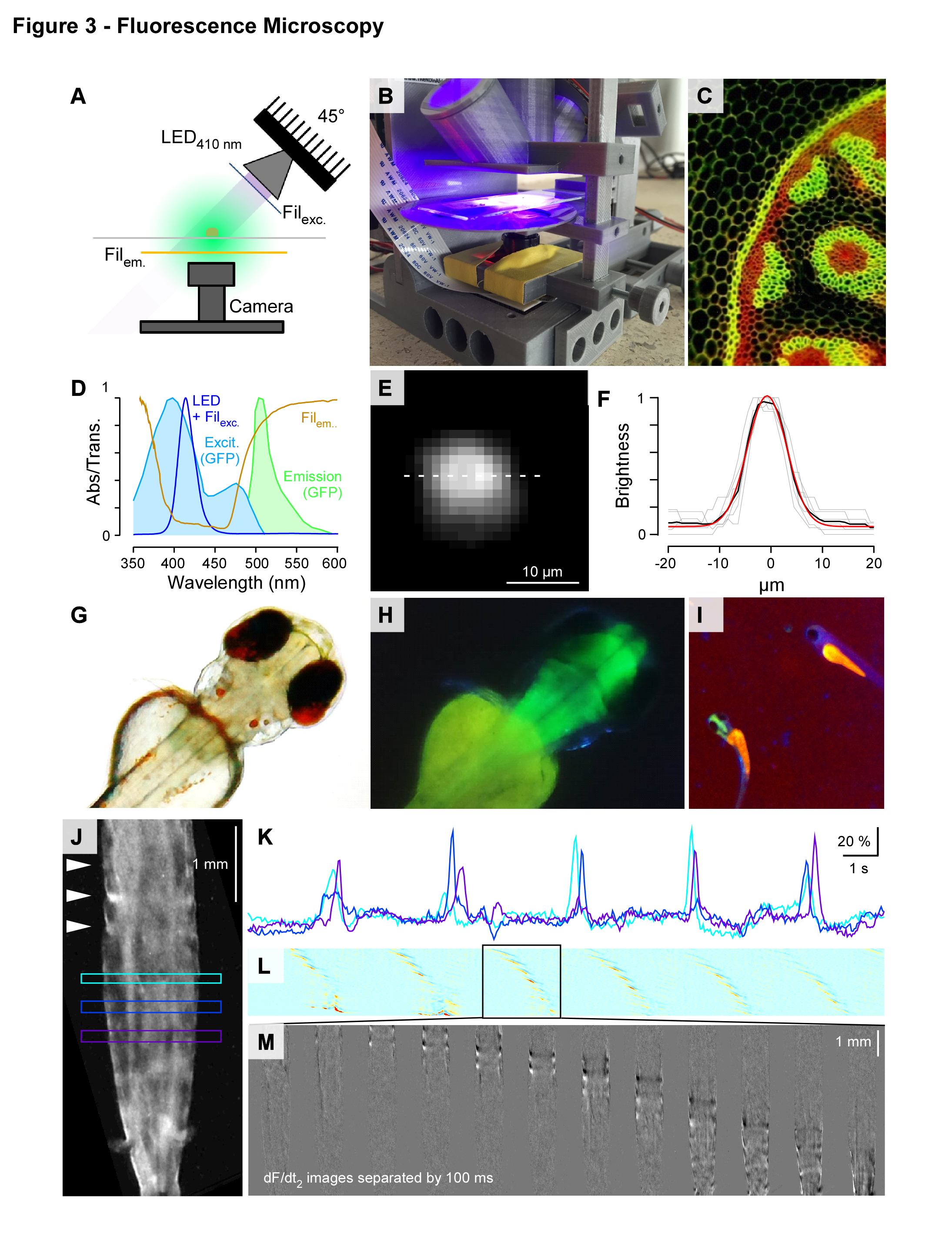
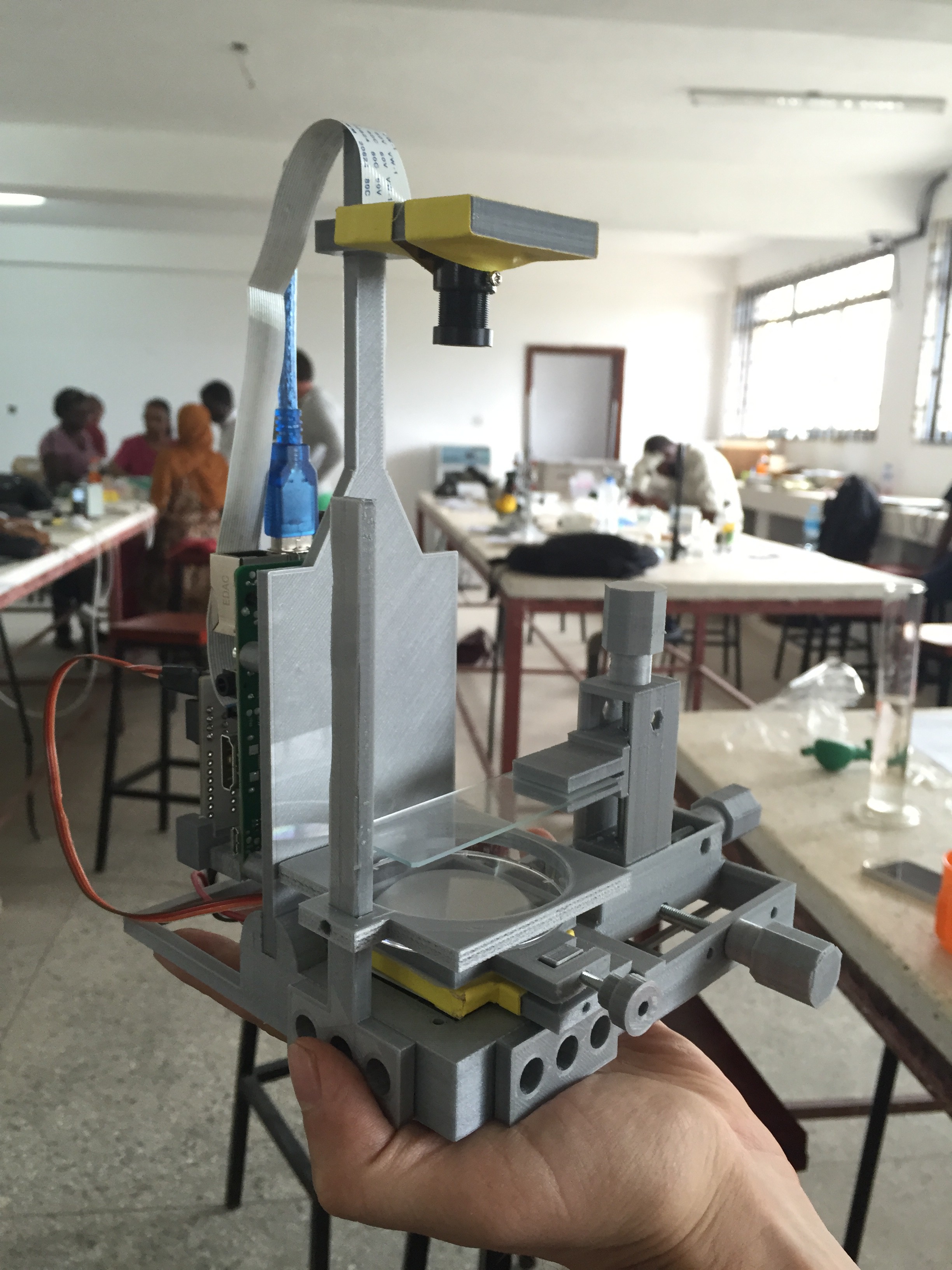
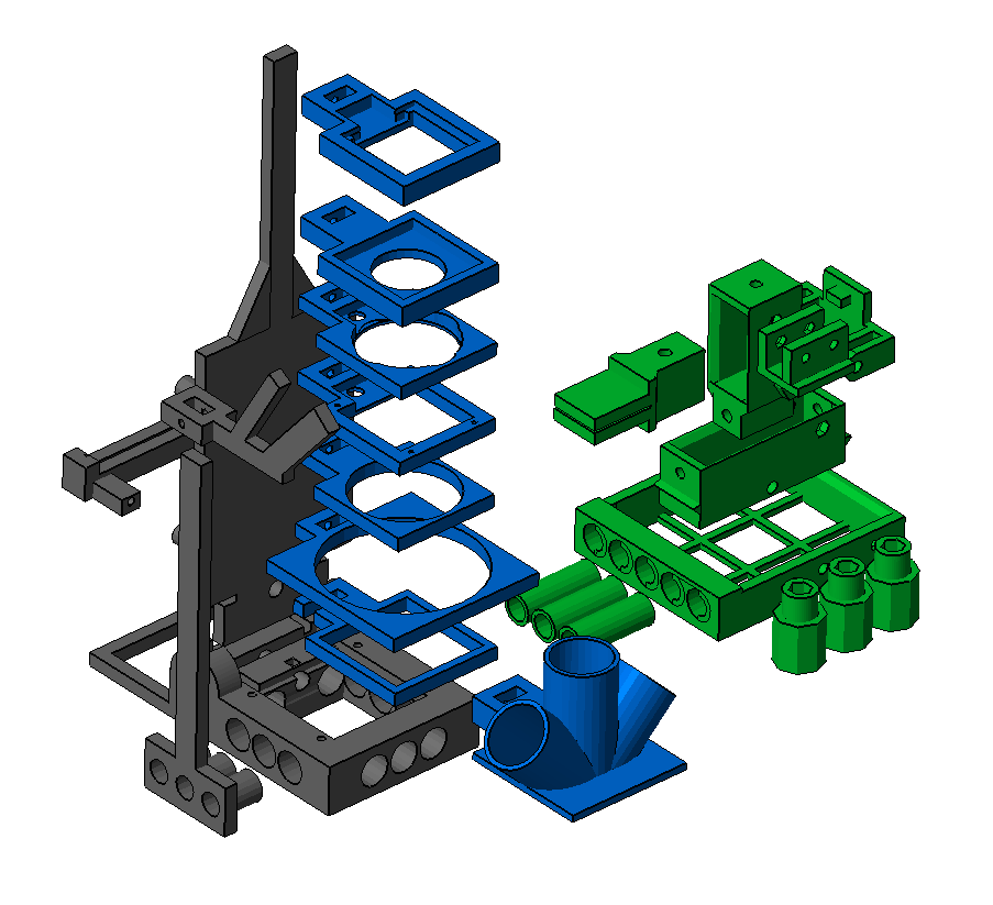
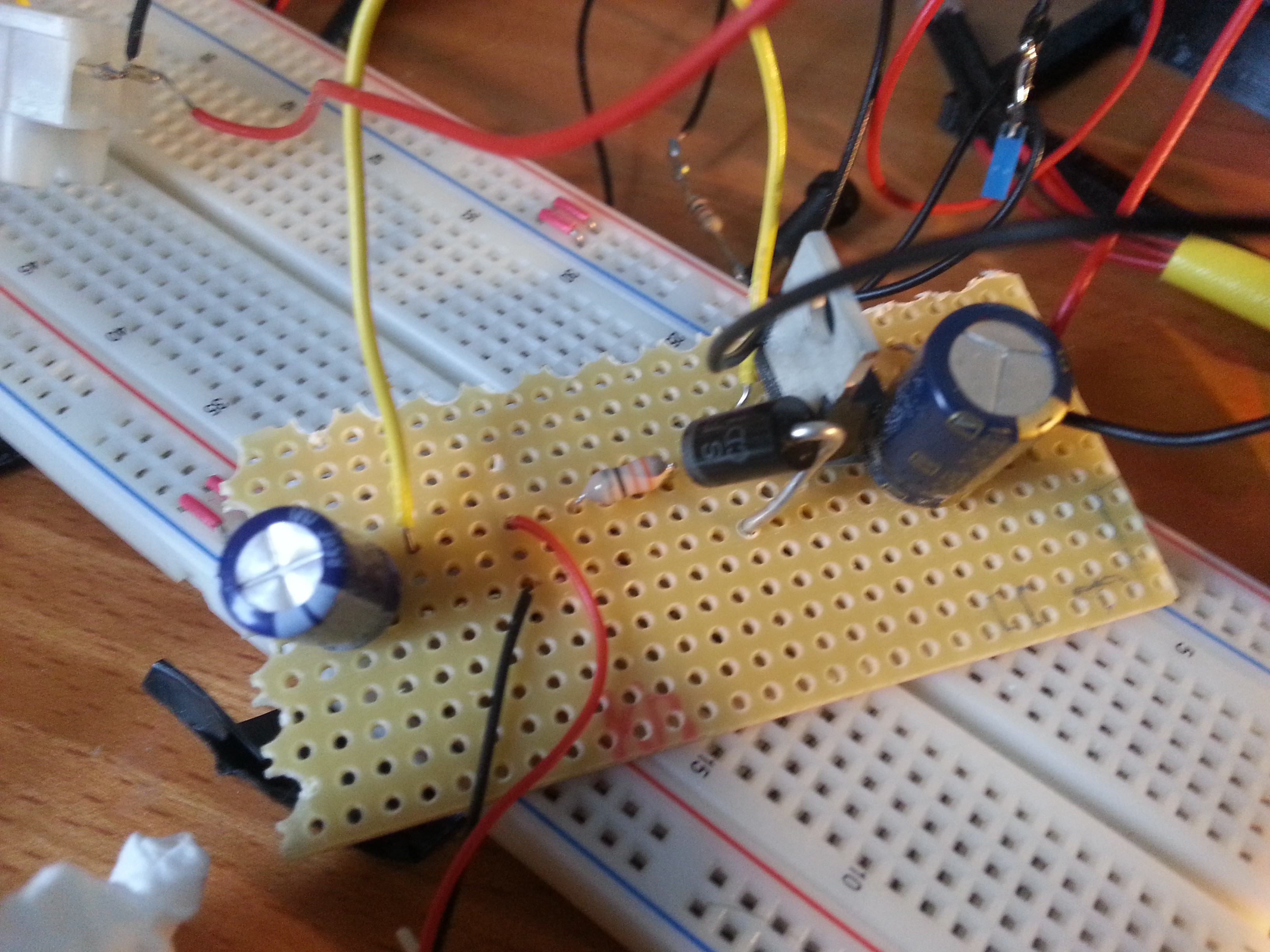
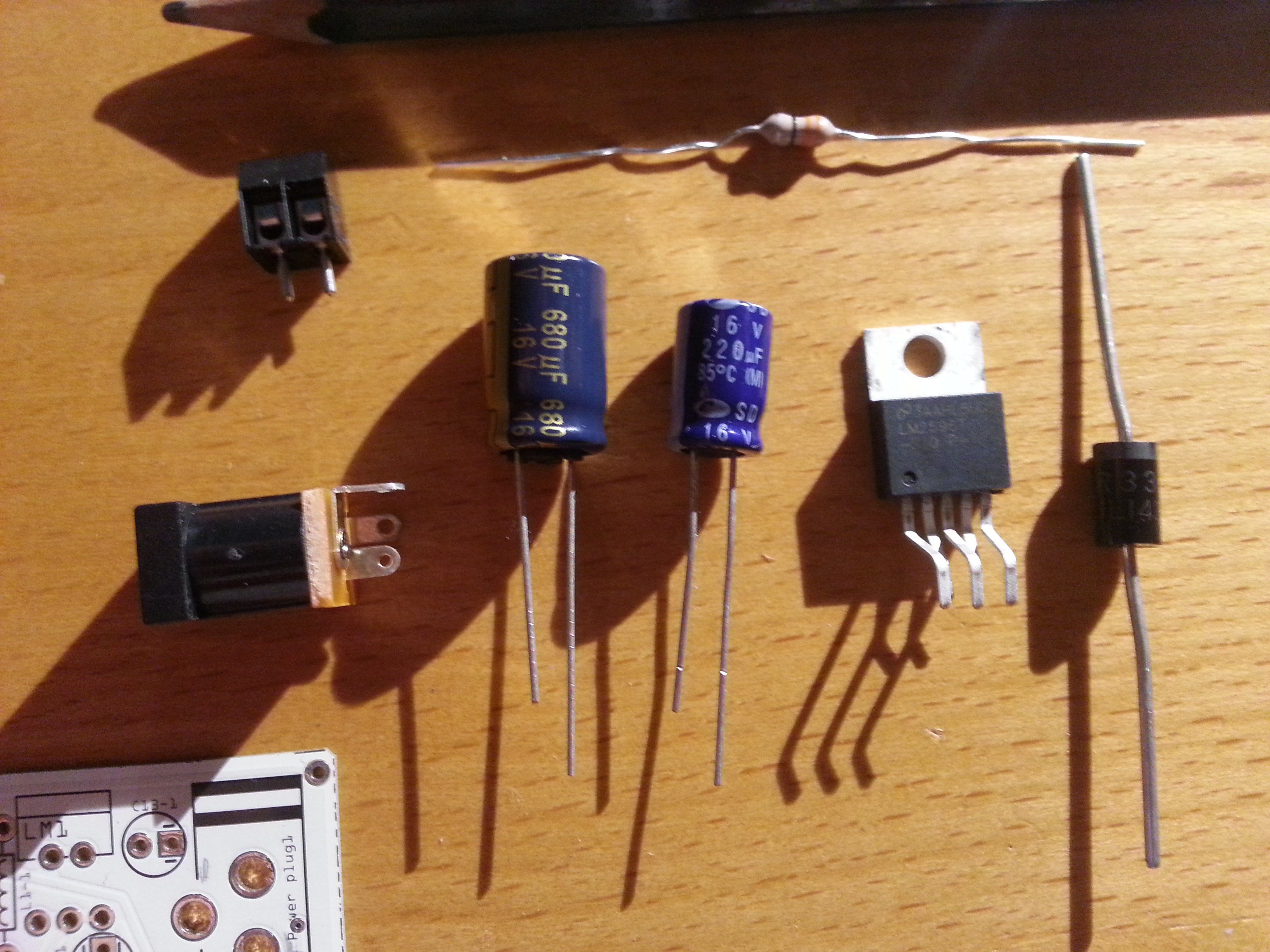
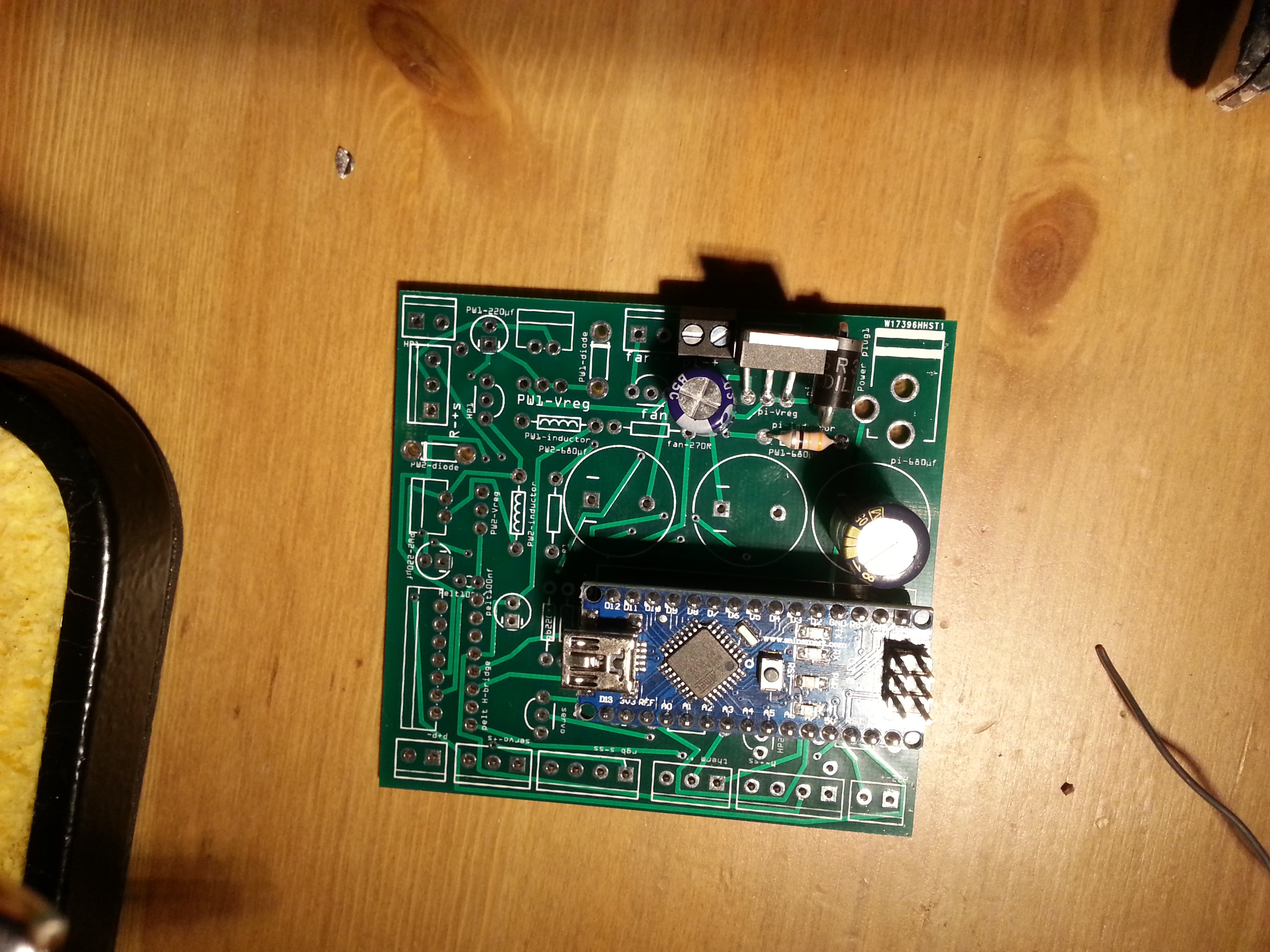
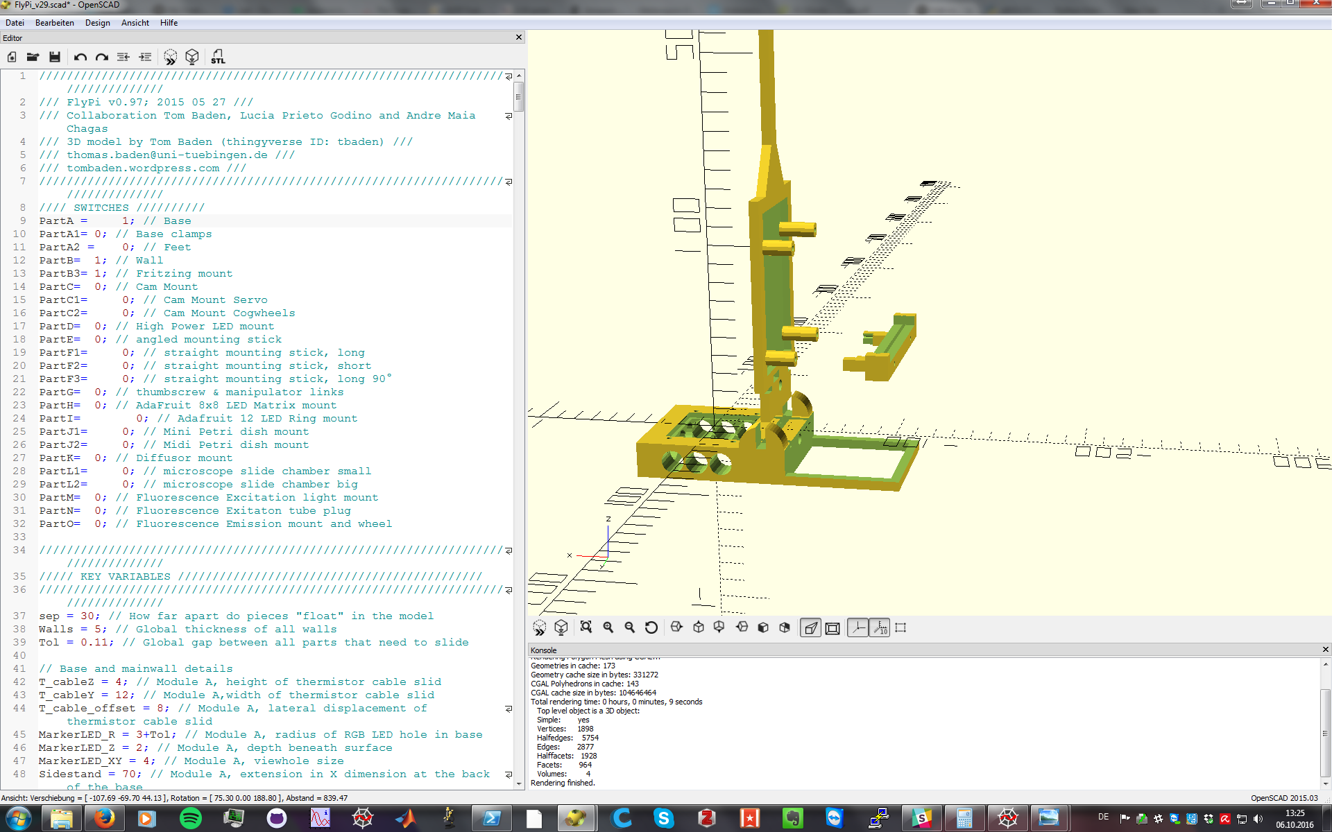
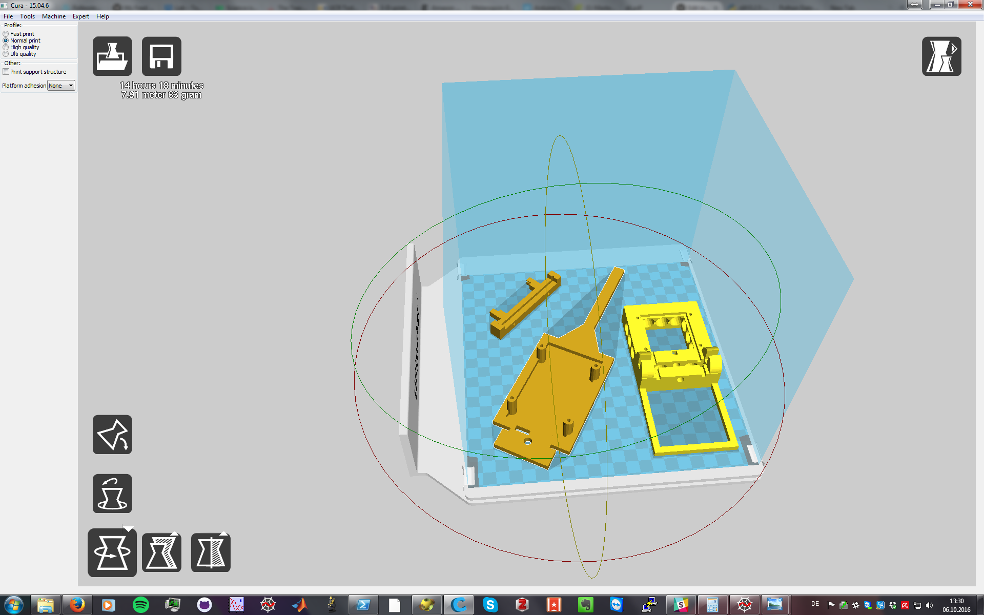
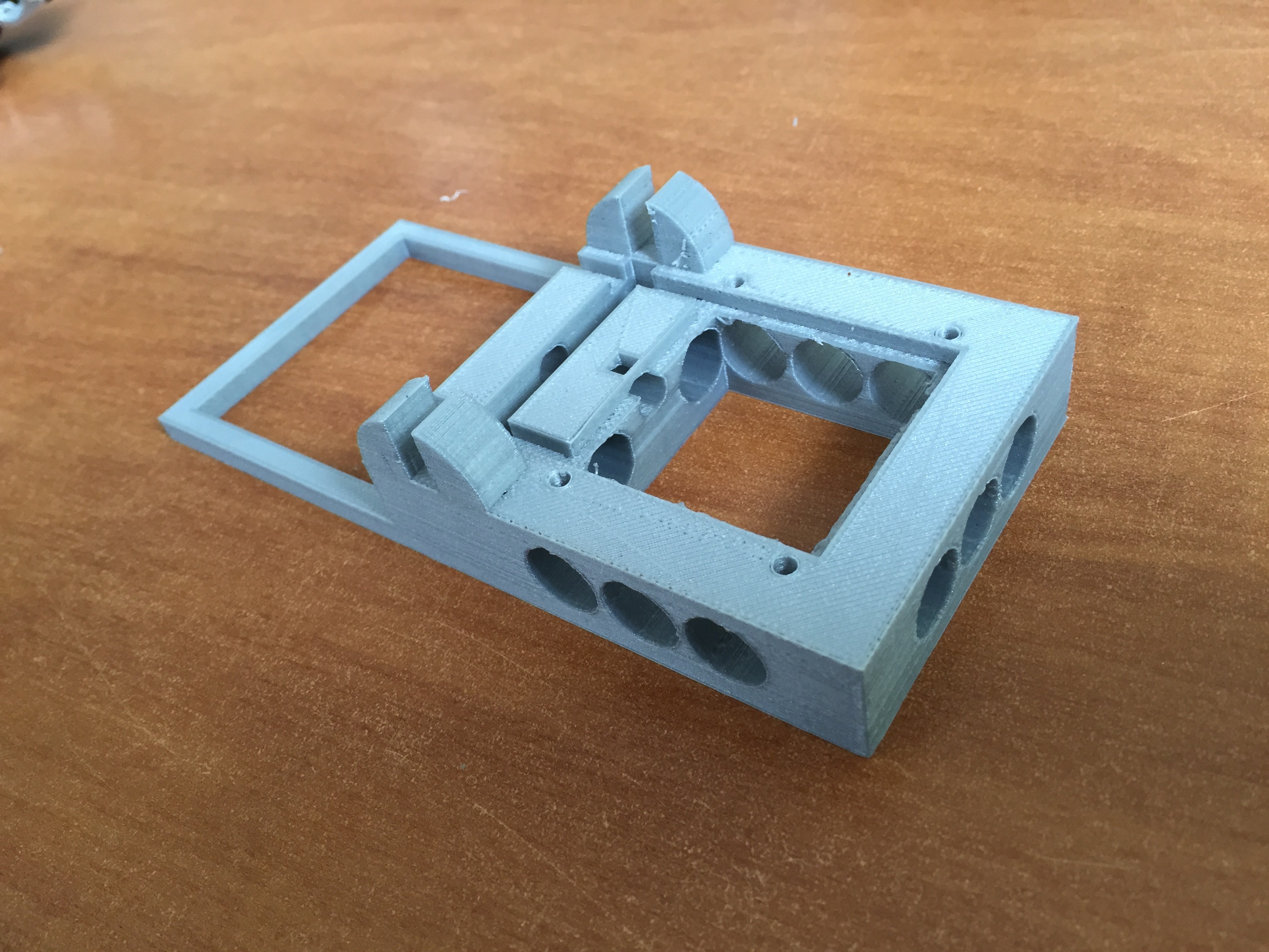
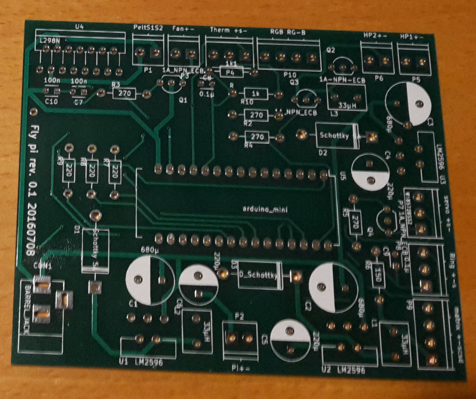
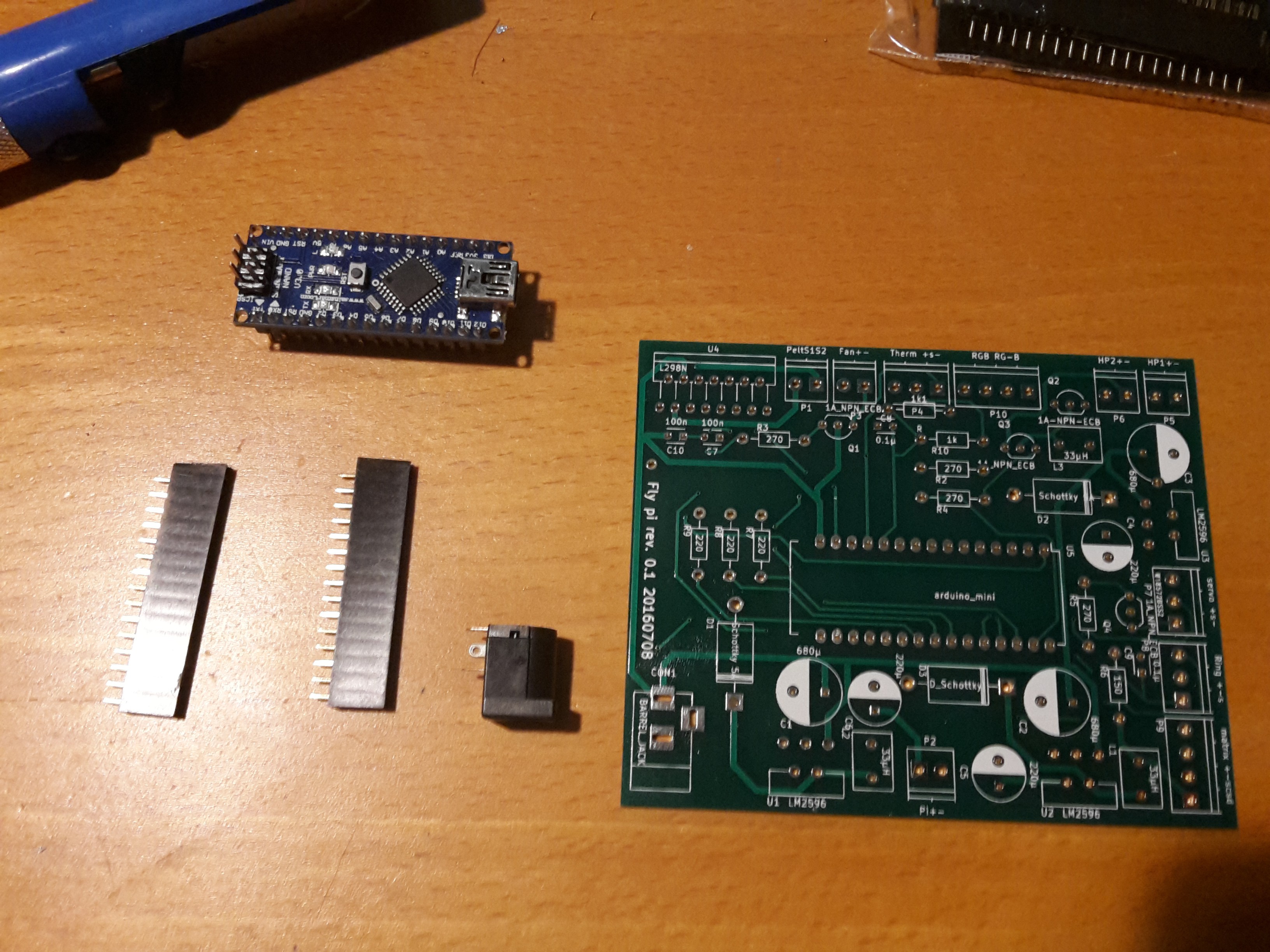
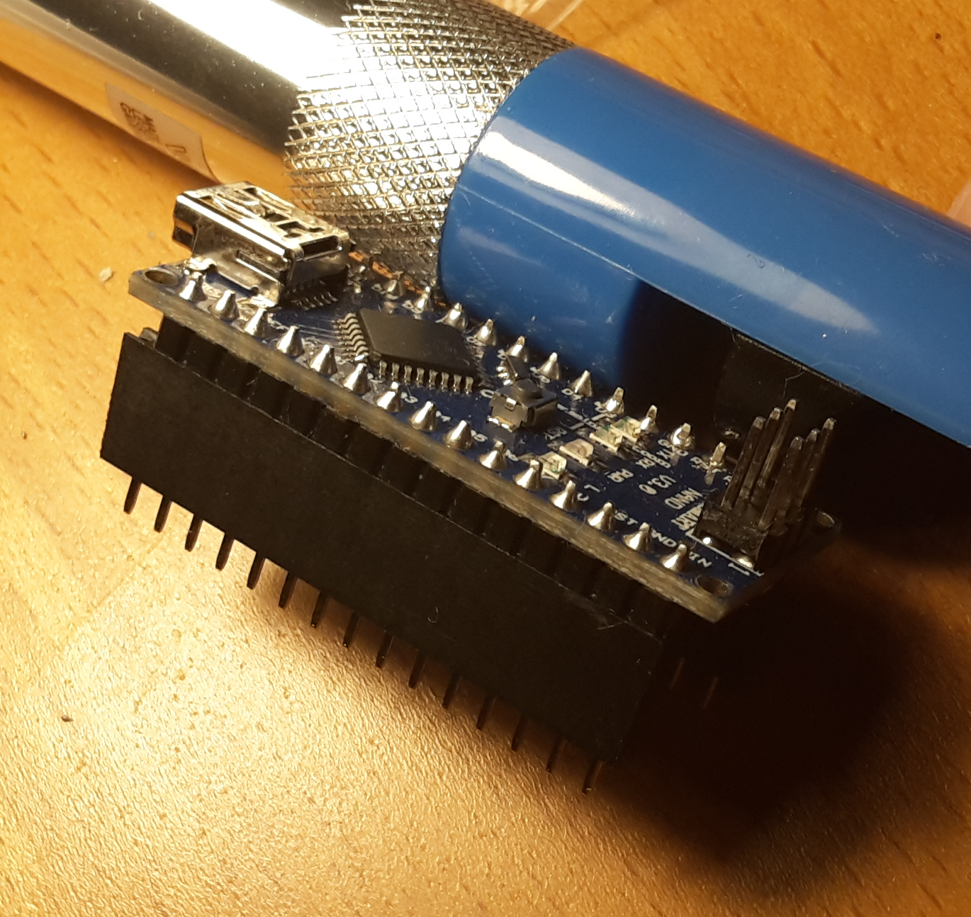
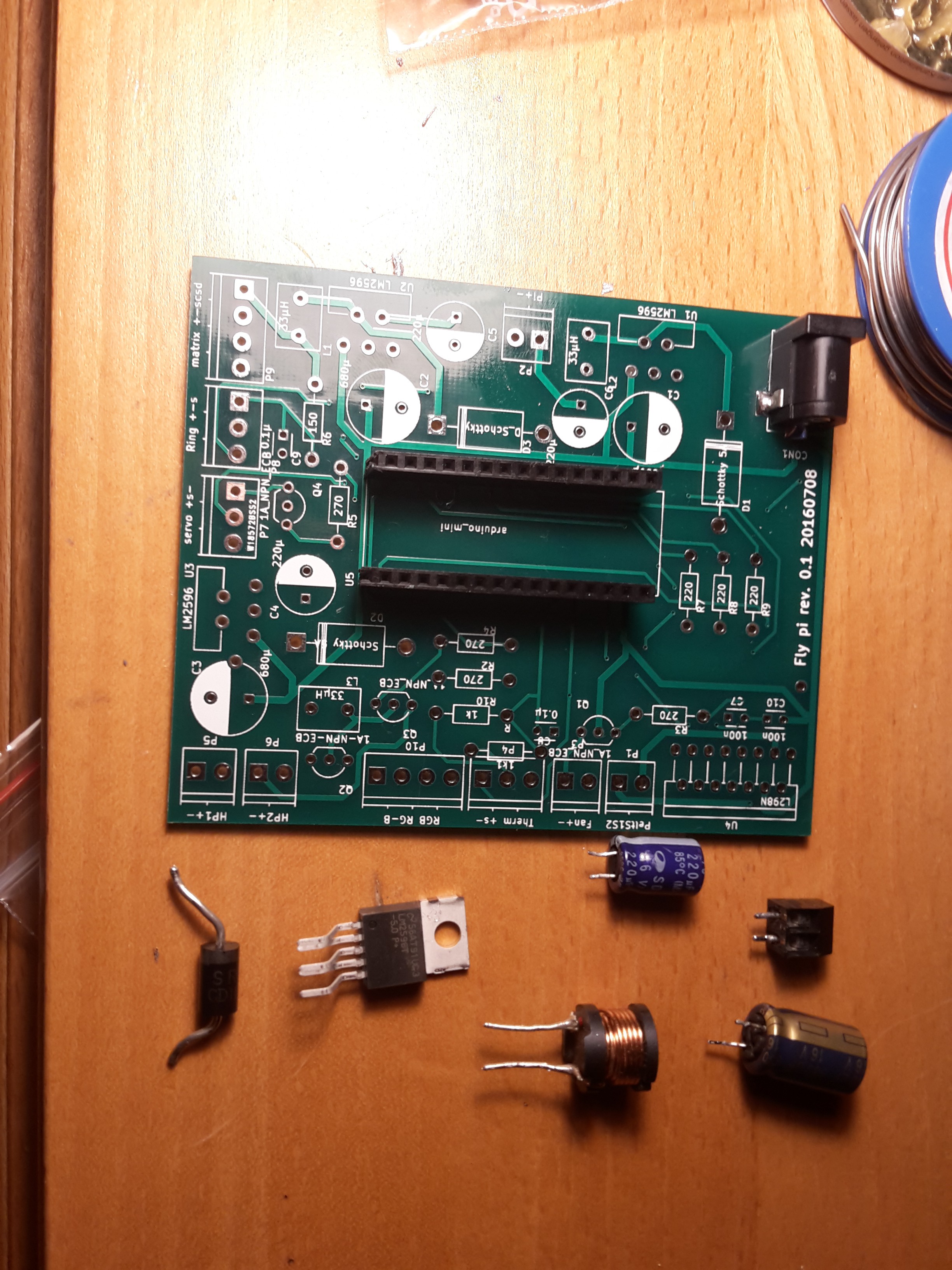
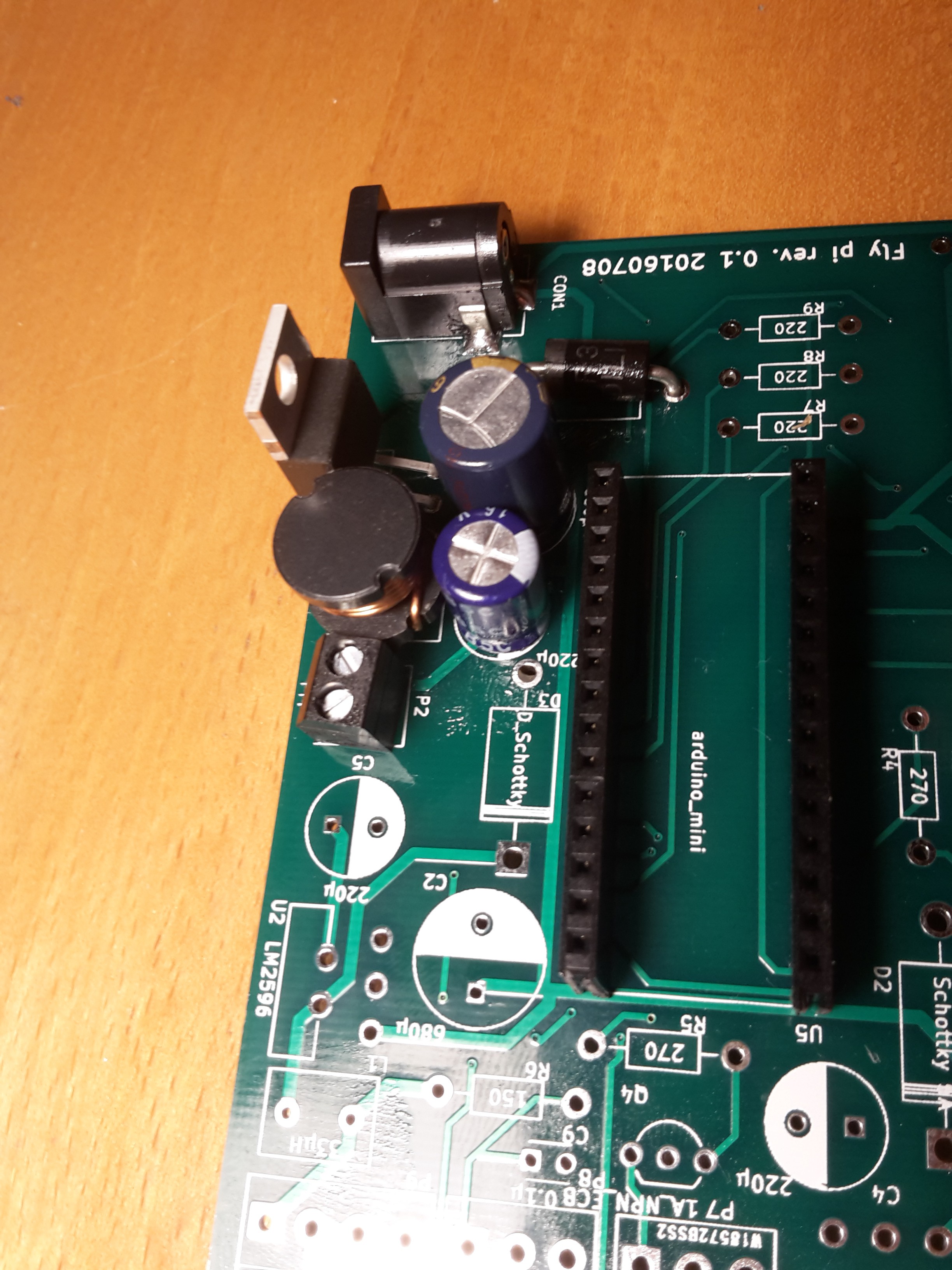
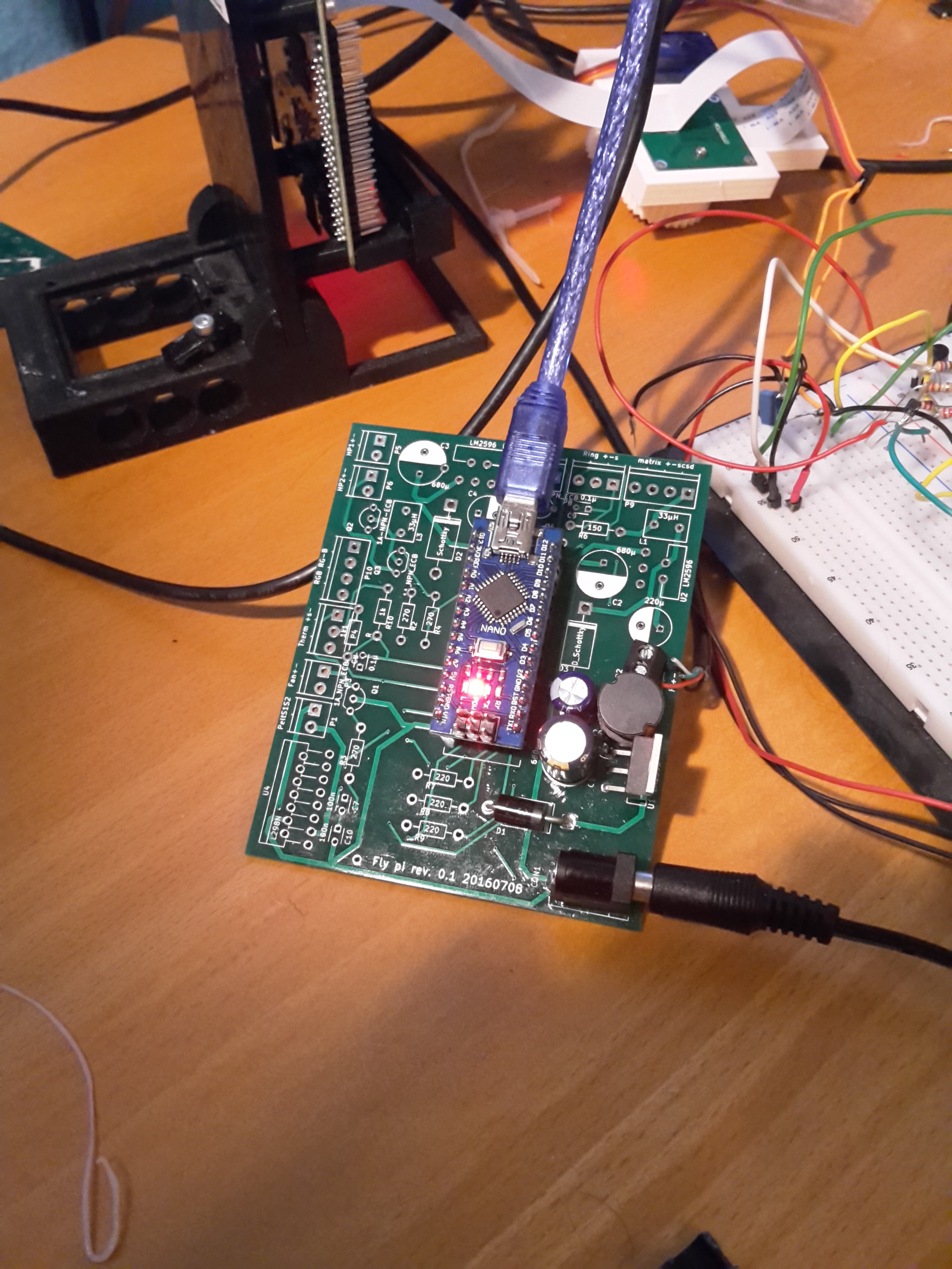
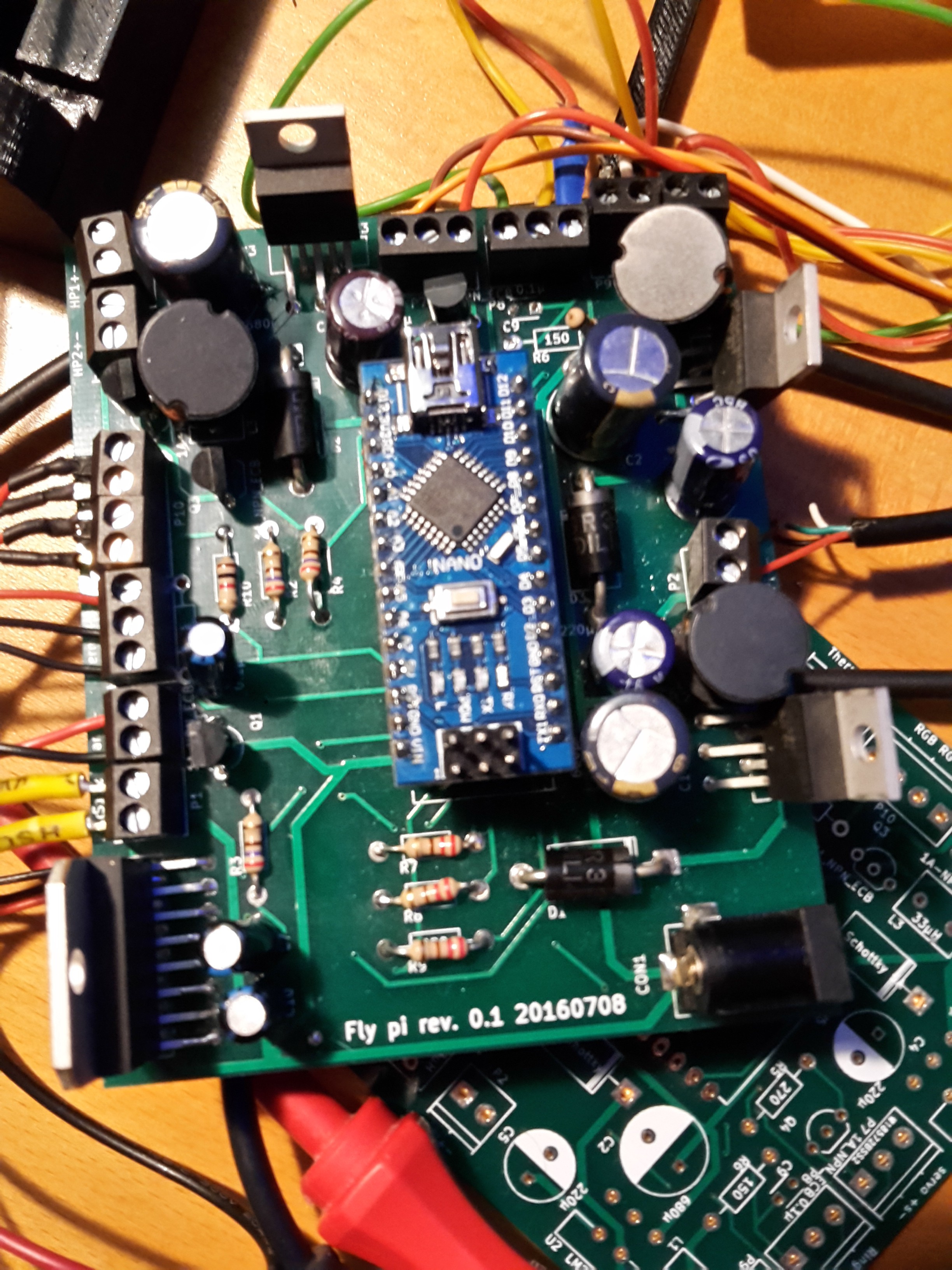
A raspberry pi 2 (or 3) (running Raspian) + picamera with mounted lens (M12 standard) + some python3 code (for custom GUI + saving of data) do most of the lifting and an Arduino + custom PCB + electronic bits take care of timing, light stimulation, heating, temperature sensing and any other physical interaction necessary.
For more details, please check: https://openlabwaredotnet.files.wordpress.com/2015/11/main-v4.pdf
 Python software schematic: How the different independent classes relate to each other
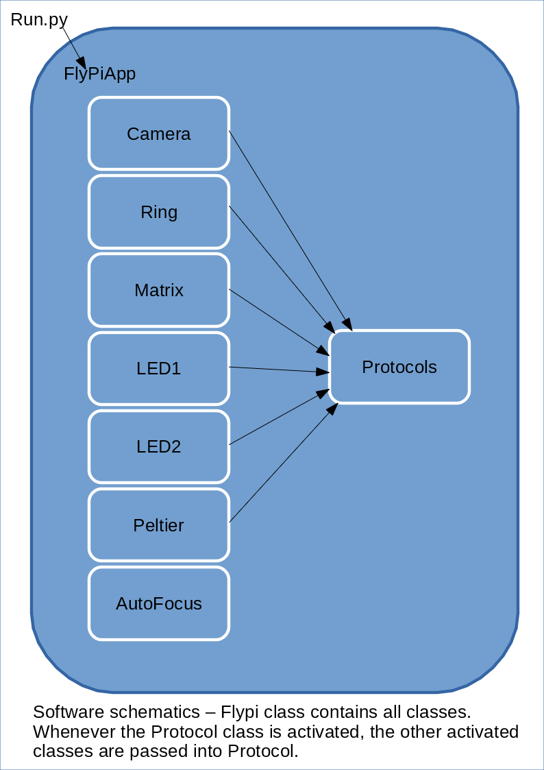


 RoGeorge
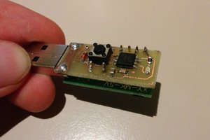
 Audrey Robinel
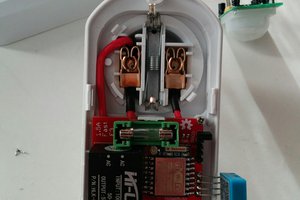
 David Davenne
Hello, I'm thinking of building this with our science group and I'm wondering if it can be done in one month or under! Also, hope it's approved because this is such a cool tool. Moreover, do you know anywhere we can buy the Rpi cam from Europe?