 Ulf Winberg
The vision I have, is to create a weather station that can be used by thousands of people around the world, all uploading data to a centralized site where trends can be monitored and can be viewed by everyone. In time, more cheap sensors can be developed, measuring for instance CO2 and oxygen levels. The price for commercial weather stations are most of the time several hundred dollars, and they require wired, or at best, battery power to work. A weather station is already exposed to different weather conditions, so why not use this to power it? You can place it anywhere and never need to change a battery. You can simply get close to it with your smartphone when you want to download the data or, if it's close enough to your home, continuously download it from a low-power and low-cost computer like the raspberry pi.
Besides collecting weather data, the weather station can be helpful determining the location of wind turbine and solar panels. Especially wind turbines are extremely dependent on where they are placed, and it is often difficult to know where there is turbulence in the air before actually measuring. To make your own small wind turbine can be as cheap as a few hundred dollars, and buying a weather station at the same price in not an option.
These are the goals that I have defined:
- Wireless communication to some base station (e.g. Raspberry Pi)
- Automatic data send, and local accumulation when there is no connection
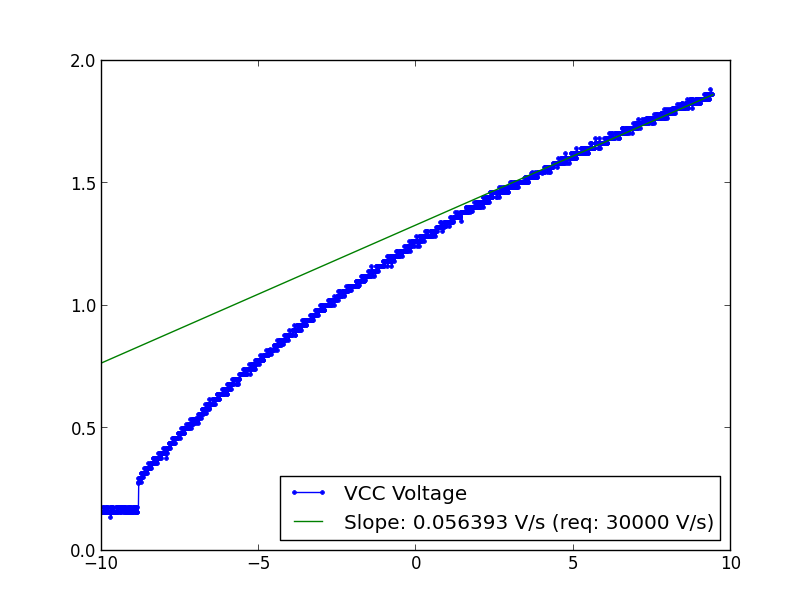
- Completely powered by the weather (sun and/or wind)
- Should measure temperature, wind, sun to start with, but make way for expansions
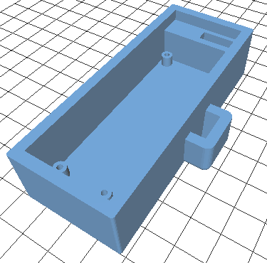
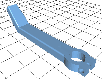
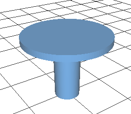
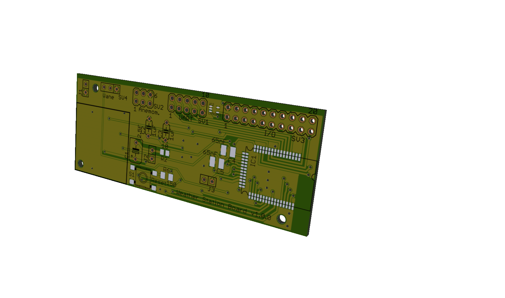
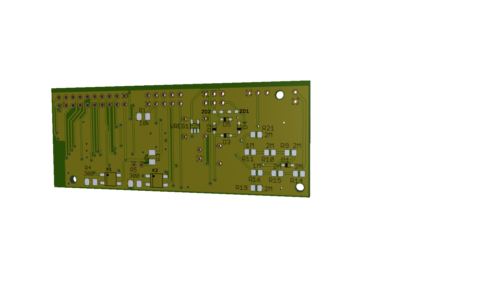
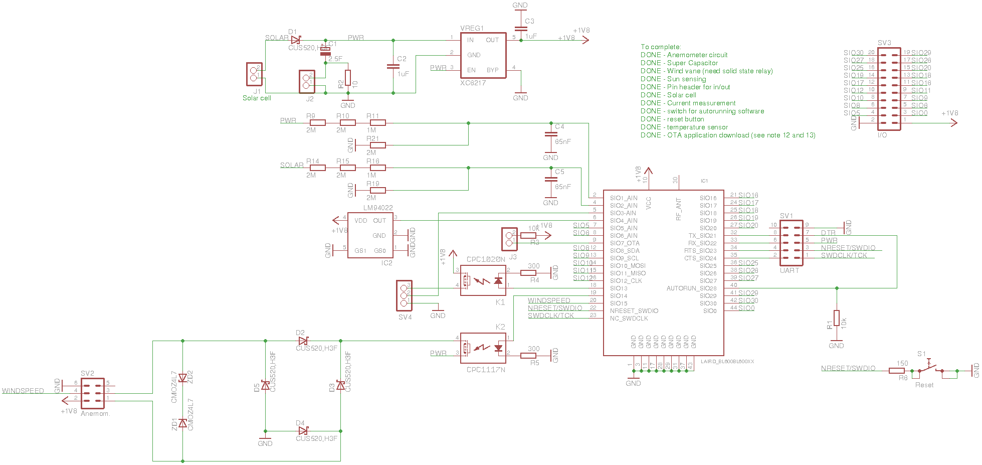
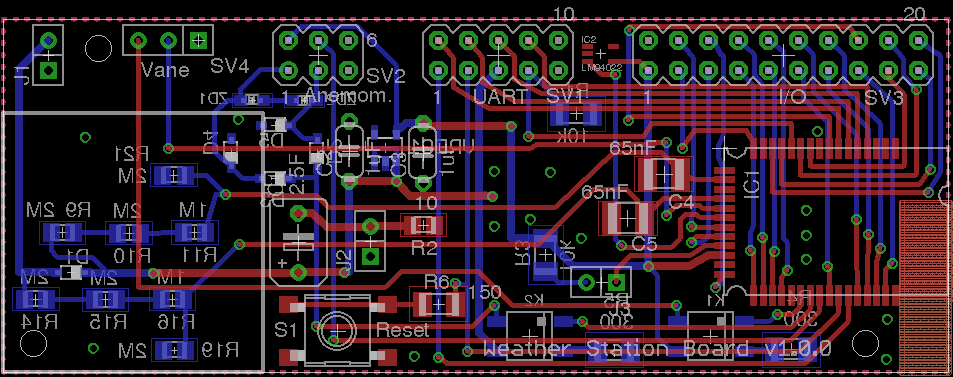
- Make everything open, including PCB layout and printable 3D parts (see github links)
I think this is a good time for a project like this, mainly for two reasons:
- Bluetooth smart is becoming popular, which allows very low power, and cheap transceivers including processors now exists.
- Super capacitors are becoming cheaper and larger (as an example, today you can find a 90 F capacitor for $ 15), which avoids using batteries. Even rechargeable batteries have quite short life time, and the charging process is more complex (e.g. trickle charging).
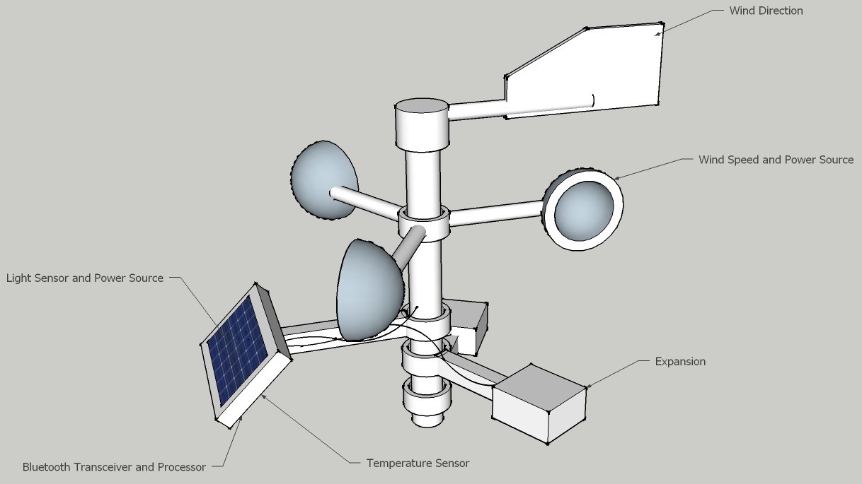
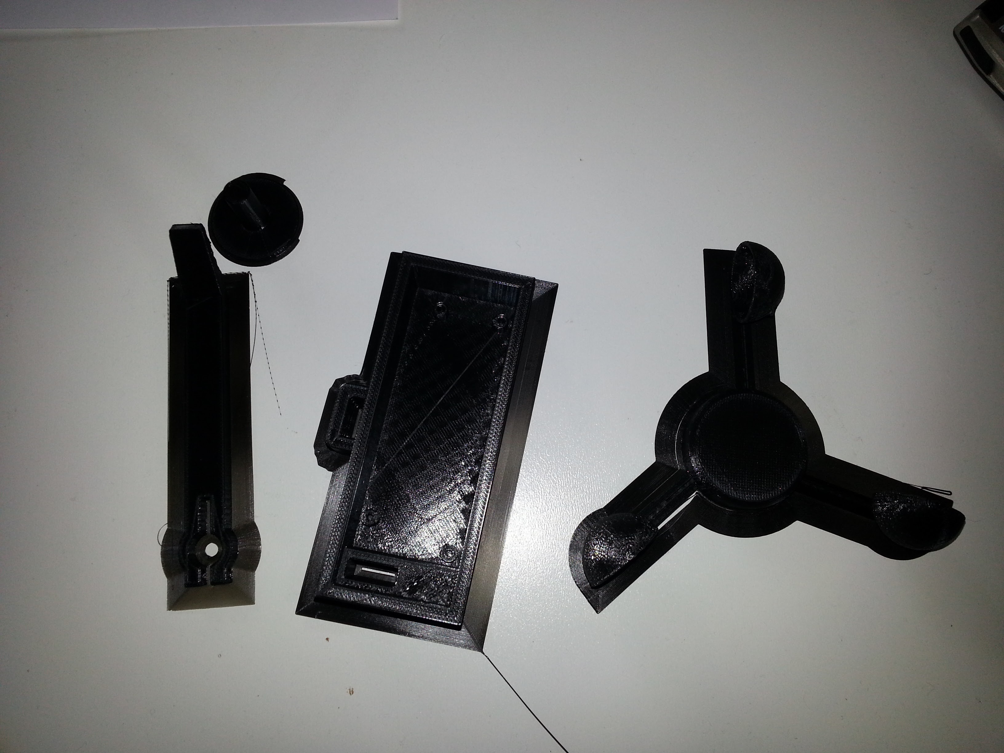
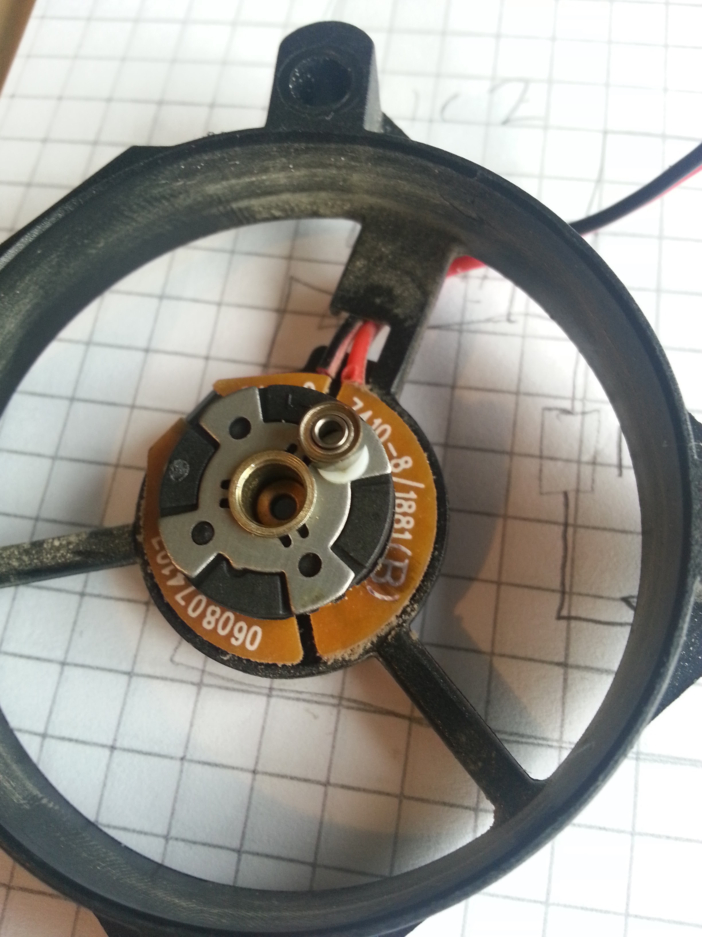
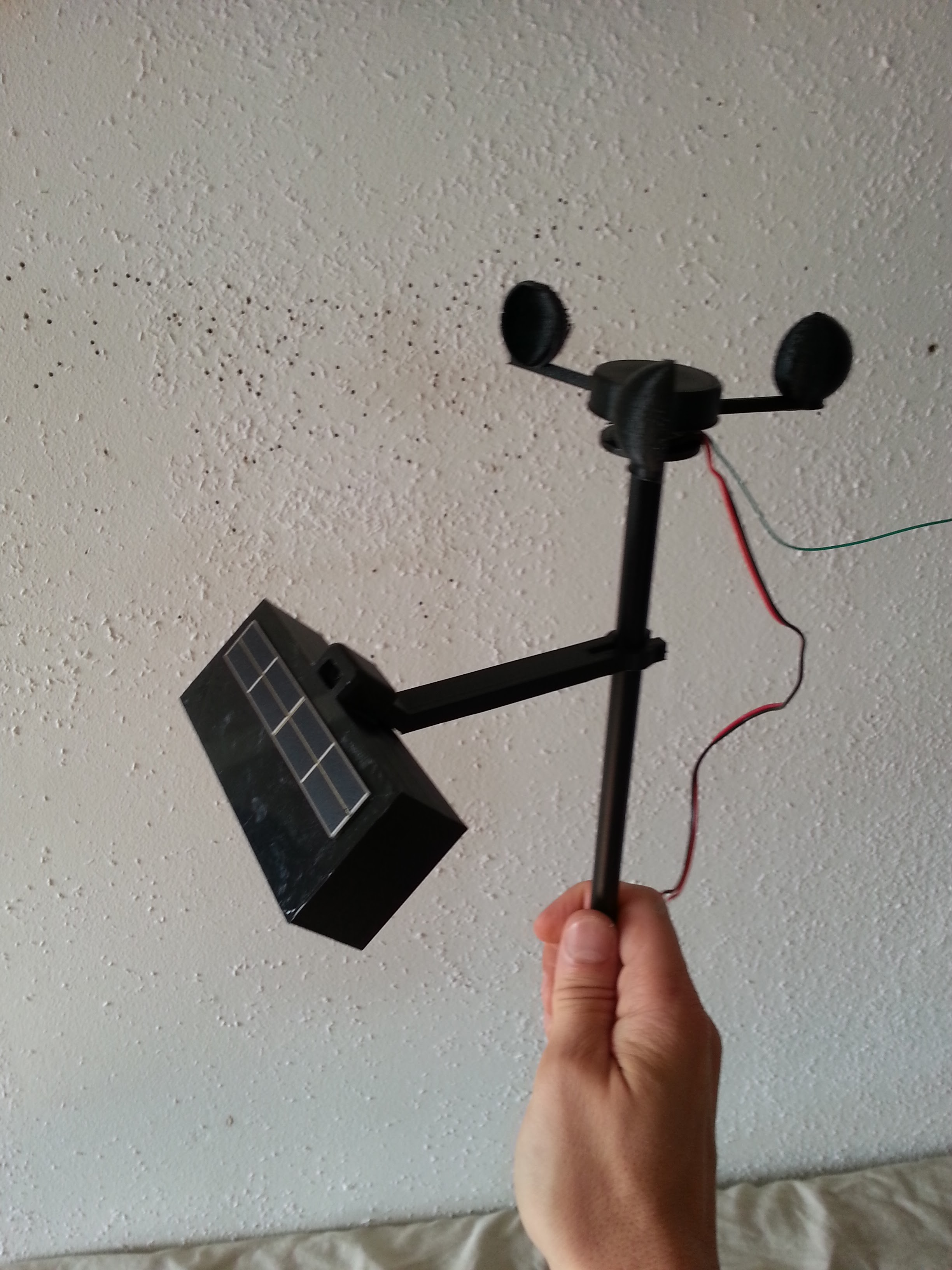
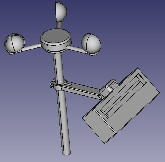
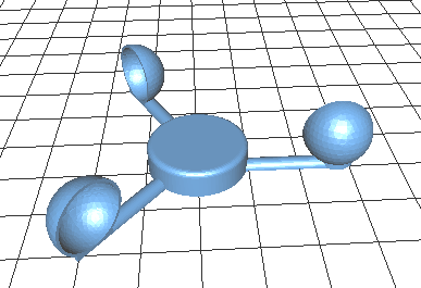
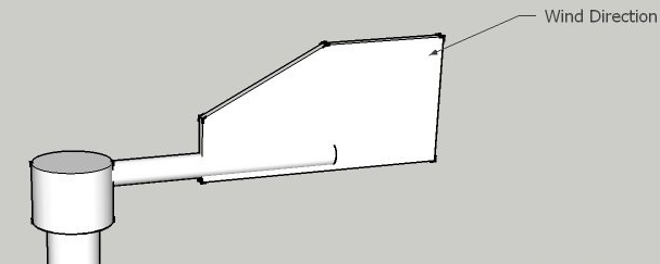
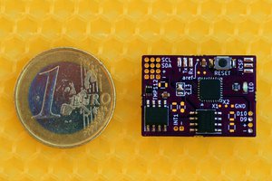
The shape I have in mind can be seen above. By using a rod as the base, additional sensor can be added easily, and simply be plugged in at the back of the solar cell. The transceiver and processor will be small enough to fit anywhere, but since the solar cell will be the primary power source, it will be placed directly under it. The temperature sensor should not be exposed to sun, and since the solar cell must be exposed, we know there will be shadow under it.


 Jan
Jan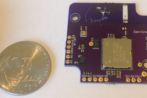
 Kris Winer
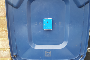
 Stephen Harrison
 Nikos
Nikos
A low cost weather station is a do-it-yourself project and it is a good way to promote interest in weather and science in general. There are two main types of weather stations: those that monitor outdoor weather and those that monitor indoor weather. You will need the necessary equipment which includes the following: * Temperature sensor * Wind sensor * Rain gauge * Anemometer * Barometer * Lightning detector * Rainfall recorder * Heated shelter for the rain gauge and anemometer
https://bit.ly/Nkqe62