In this project log, I'm going to share with you a new method for easily controlling a stepper motor, which I haven't seen anywhere else before, and definitively falls into the "hack" category, in my mind.
Alright. In my previous blog, I already mentioned that a stepper motor requires a pulse signal to change position, and a direction signal to change direction. How can we easily and cheaply do this with a computer?
BTW: originally I wanted to use a microcontroller to move the mirror, but when I revived this project, I decided I would rather make it much easier for someone to copy and use my project and tinker with it. Also, when things are running on a computer, it is just so much easier to log data and to configure the system.
So how can we do this cheaply with a computer?
First of all, National Instruments have come out with the community version of Labview. If you haven't been in touch with labview before; it is a way to visually create programs. Even though I know how to program C for microprocessors and also C# on the computer, in my mind nothing beats Labview to quickly create a program with a nice looking Graphical User Interface.
You can download Labview community version from here:
https://www.ni.com/en-gb/support/downloads/software-products/download.labview.html#343639
Normally, Labview costs several thousands of dollars, but luckily the community version is free for non-academic and non-commercial use. On the flip side: the free version doesn't allow you to compile your program and run it on other computers, so you'll have to run it on the computer which you used to create the program.
Labview will be used to track the time, and control stepper motors which determine the mirror angles.
Secondly, to get the signals on the computer to the stepper motor drivers we are going to use.... serial port converters, also called UARTs, or USB-TO-RS232 converters.
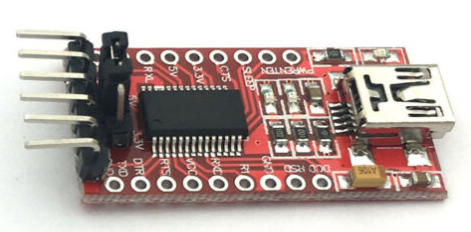 That's right, we will use el-cheapo USB to UART converters to control motors. Normally, these converters are used to send serial characters, and we'll "creatively use them" to create motor pulses instead. In order to understand how, we'll have to dive a bit deeper into serial port signals.
https://blog.digilentinc.com/uart-explained/
The signal below demonstrates what appears on the "TX" output of the USB-TO-UART. The signal level which is normally transmitted (no communication) is at 3.3V. When sending any signal, first the "start bit" is sent, which is a low signal with 1.5 X the time of a bit. A bit is shown as d0..d7. The baud rate is equal to 1/(bit length). The stop bit at the end is not really relevant for this purpose, it is also present to detect the length of the "frame", where a frame is everything from the negative flank before the start bit to the positive flank after the stop bit, and helps the receiver to detect the correct signal if the baud rate is not super accurate.
Because there are 8 bits (d0..d7), 256 values can be sent, which in hex represenation equals "0xFF". So if we send 0x00, we get the signal as shown... and that is going to be used as one motor pulse!
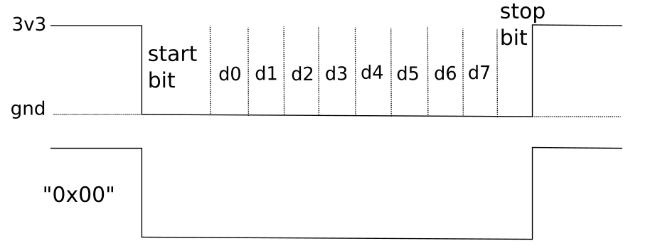
So it's super easy, by sending the character 0x00 via the serial port, we are sending once pulse to the stepper motor driver. That is sufficient for our purposes. But if you want the motor to spin faster, or if you cannot send the character 0x00 for some reason (because it's not a type-able ASCII character such as 0..9 and A..Z), you can use the character 0x33, which stands for the number 3 (http://www.asciitable.com/).
Let's type 0x33 into the windows calculator set to "programmer", and see what we get:
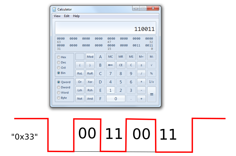
So by connecting the ft232RL to your motor driver, opening up your favourite terminal such as https://realterm.sourceforge.io/, opening the serial port on a baud rate of, say, 57k6, and typing in 3 on your keyboard, you tell the stepper motor driver to move 3 steps, or 3 times 1.8 degrees.
In our case, we also want to set the direction. Well, RS232 has several signals to control "handshaking". What is handshaking? The simplest form of RS232 has ground, TX for sending to the receiver, and RX to receive the answer back. But what if the receiver is busy at the moment? That is where the handshake signals come in.
https://en.wikipedia.org/wiki/RS-232
For instance, RTS stands for "Ready To Send", and is used to signal that the receiver is ready to receive something.
What is confusing is that it's sometimes the other way around, it all depends on which unit you define as the receiver, and which as the sender.
In any case, Labview allows you to control these signals. So by "setting" this signal, you can send another signal from your FT232RL to the motor driver.
Similarly, remember that limit switches were supposed to be used? We've got two actuators and thus two of those switches. By pulling up one terminal of a switch to 3v3 with a 10k resistor, and connecting the other switch terminal to ground, the resistor voltage will be high when the switch is not engaged, and low when the switch is engaged.
This signal can be connected for instance to CTS ("Clear To Send"), and can be read from Labview.
I'll post and discuss the entire schematic in the next post.
Discussions
Become a Hackaday.io Member
Create an account to leave a comment. Already have an account? Log In.