On a previous post I already discussed why I chose Labview to create a prototype. I like how it very quickly and easily allows you to create a prototype.
I've installed the free (for non-commercial and non-academic) community version 2020.
https://www.ni.com/en-gb/support/downloads/software-products/download.labview.html
Let's dive right in.
Remember that I'm using the FT232RL usb to uart converter? I'm using the TX to send a pulse, and the DTR output to set the direction.
This little sketch allows you to play around with it.
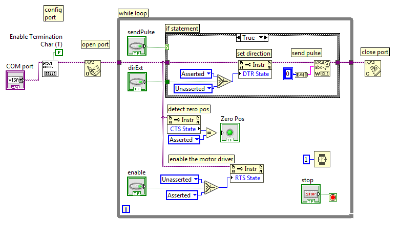
First the COM port is opened. You'll have to figure out for yourself which one that is. What I typically do is open the device manager in windows, look at the list of COM ports, and disconnect and connect the FT232RL device. The device which disappears from the list and reappears is the one you want.
The COM port is then configured with all the standard settings (9600 baud, 8n1), but the termination byte is disabled. This is a newline character, and we don't want this: we only want the bytes we want to send to appear on the output and no extras.
Then there's a while loop and within the while loop it polls the sendPulse button. If that button is pressed on the GUI, a serial character 0x00 is sent, which appears as a single pulse with a length of approximately 10/9600 = 1 ms length. Within the while loop there is another button, and if that is enabled, its value will be carried into the if statement when it is executed, and the motor will turn in such a way that the actuator extends, and if disabled, the actuator withdraws.
The direction is wired in such a way that it executes before the "send pulse" is executed. This is important for counting the pulses in the correct direction in order to figure out where the actuator is.
There is a button "Enable" which, when enabled, enables the motor driver. When disabled, the motor driver is put in standby and doesn't energise the motor. If you're playing around with this code, you'll notice that the motor refuses to move when the motor driver is enabled.
Finally, the CTS state is checked, and this line is connected to the switch. So when the switch is pressed, the CTS state is asserted, and through a comparison "equals" block, turned into a boolean LED signal.
This is all which is required to control the motor and detect the zero position!
Didn't I say it was a super simple way to control a stepper motor actuator?
There are a few details: there is a time delay of 1 ms in the while loop so that the pulse repetition is slowed down to maximum 1000 per second, and if the program is stopped, the serial port is closed again.
In order to use this bit of code as a subroutine, there are some small changes:
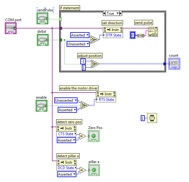
The picture above shows the contents of the subroutine. The while loop is removed, as well as the "open port", "configure port", and "close port". Those things will be handled in the main routine. Executing those things every time you run this code slows it down enormously. The inputs to this subroutine are "COM port", "sendPulse", "dirExt", and "enable". The output is "Zero Pos". I've shown what this looks like below. Notice I've added a detection whether this COM port is pillar a or pillar b. Remember from an earlier project log that pillar a is connected to ground, and pillar b is connected to 5V, so that from Labview I can determine which COM port corresponds to which pillar.
There is also a bit of code that helps counting the position of the actuator: if the direction is "extending", then the count is -1 and else it is +1.
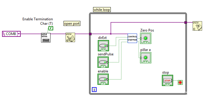
This is what the main loop looks like up to now: the "control stepper" block contains the subroutine described above. On the left of the "control stepper" there are four inputs (3 buttons and the link to the COM port), and on the right of this block are the two outputs; "zero pos" and "pillar a".
I haven't yet figured out how to add the source code of this Labview program to this project log, but the screenshot is the source code, really.
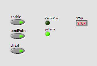
This is what the Graphical User Interface looks like:
This of course is not all of the program. Let me try to describe my plans first.
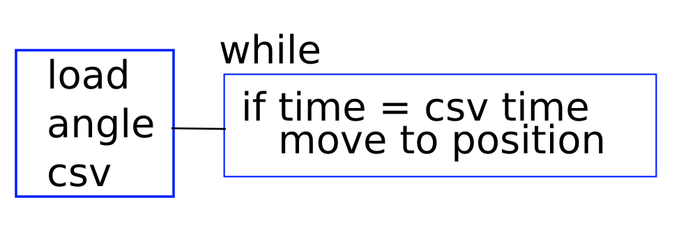
The above program describes how it will work, really. When the program is started, a CSV (comma separated value) spreadsheet is loaded. Within the CSV file, the first column contains time stamps in ascending order. The second column contains the angle of pillar a (see an earlier project log which describes how it's all built), and the third column contains the angle of piller b. These pillars control axes which are perpendicular (at 90 degrees angle) of each other.
When the CSV file is loaded (into a Labview structure or array), the main while loop starts. This loop keeps running until the user shuts the program down. Within the while loop, the time is continuously compared with the CSV data, and when the time is larger than one of the CSV rows, the program checks whether it is already in position, and if not, it moves to this position.
Not shown are some details, such as: figuring out what the current position is by keeping track of which pulses were sent, detecting the DCD status to automatically figure out which COM port is which axis, and things like that.
Once a day, there should probably be a possibility to "zero" the system, so that the required position is actually the position it has achieved.
Discussions
Become a Hackaday.io Member
Create an account to leave a comment. Already have an account? Log In.