 Eric Herbers
Overview:
The display shows the following:
-Battery Voltage
-Input Voltage (wind, solar, etc) (averaged over the last ten readings)
-Amperage (averaged over the last ten readings)
-Wattage (averaged)
-Transistor Temperature and Duty Cycle (these two values alternate between each other)
-Amp-Hour counter
As far as features go:
-Automatic backlight control; if no input voltage for 60 seconds, backlight turns off
-Automatic reset of Amp-hour counter if an hour elapses with no input voltage
There might be enough overhead left to stream serial data to a PC, but I would recommend using a 16 mHz MCU. This code is written specifically for a 12 volt system with the charger in charge control mode. There are options for 24 and 48 volt settings which do change the scale of some of the voltage readings as well as other unknowns.
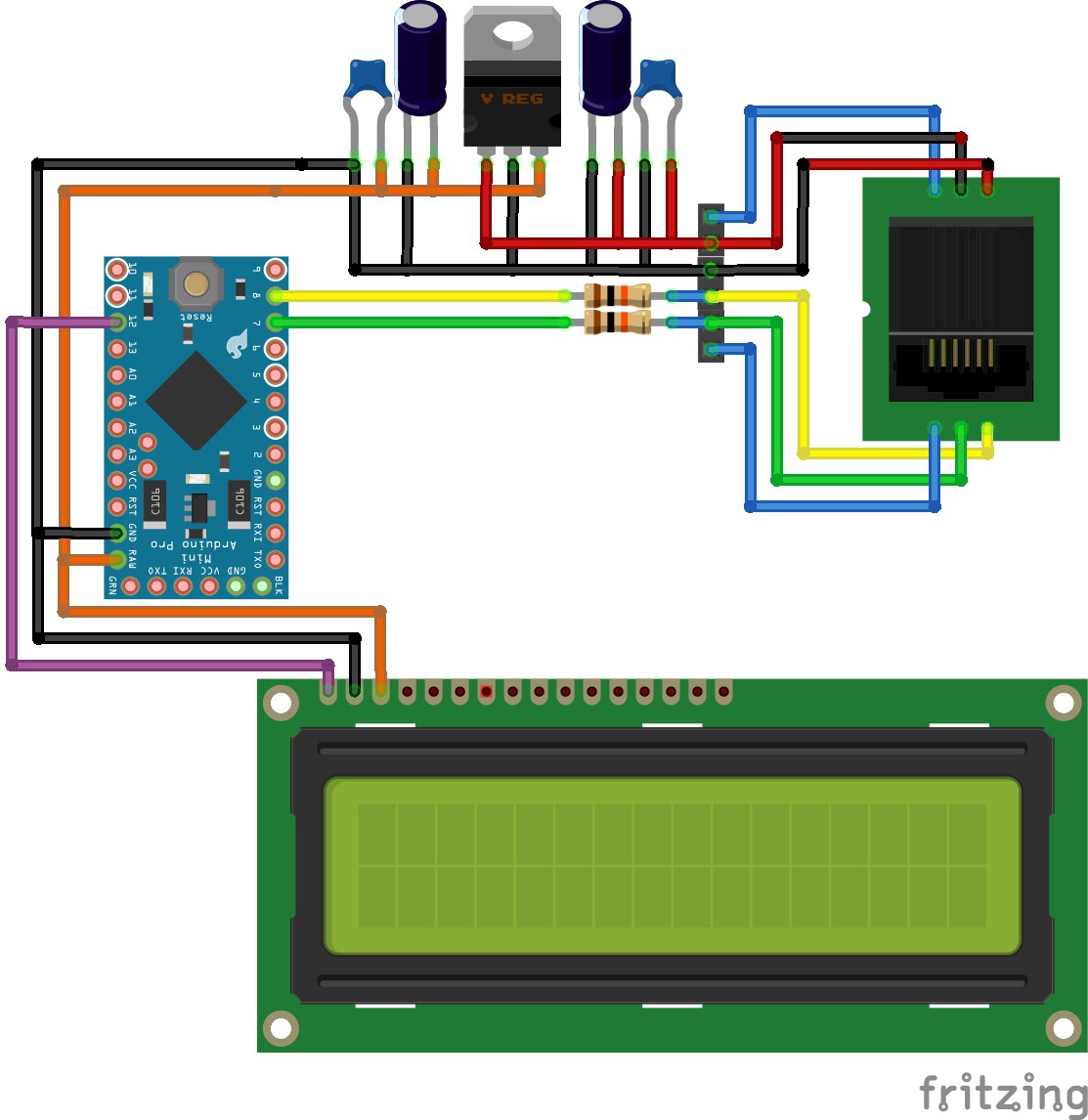
Schematic:
The schematics are fairly straightforward. The important bit is the wiring of the RJ25 plug:
- LED A
- Comm 1
- Comm 2
- Ground
- V+ (8 volts)
- Led B
Pardon the LCD, Fritzing doesn't have a serial LCD I could pick from. The purple lead is merely a serial Tx from the Arduino. The two LED leads are currently not being used, but otherwise are used to relocate the status LED that is normally found on the charger.
Source Code:
Ultimately the code is not as clean as I care for, but with the challenge of not using any interrupts it was necessary to break up functions and control when they could execute. This is done by using the time between bytes (which is longer than the time between bits) to perform calculations and stream data to the LCD. I tried to be healthy with the use of comments so hopefully it makes a little sense!
This is all written under the Arduino 1.0.6 IDE.
/*Digital Volt Meter for the Xantrex C-series charge/load controllers. Configured to read the obscure communication
protocol they use and display the information on a 2x16 Parallax LCD. Displays battery voltage, average amperage,
watts (calculated from average amps), input voltage, transistor temperature, duty cycle and total amp-hours. LCD
backlight is programmed to turn off after a period of no charging to conserve power and serve as a night mode, amp-hour
counter is also programmed to reset at night so amp-hour counter will perform as a daily counter, not total.*/

#include SoftwareSerial lcdSerial(11,12); //rx,tx configure softwareserial for LCD

//pin declarations
#define comm1pin 7
#define comm2pin 8
#define LED 13
#define LCDrx 11
#define LCDtx 12

//configurations declarations
#define noPowerTimeLimit 60000 //time in milliseconds in which display backlight turns off if not charging
#define noPowerAHTimeLimit 3600000 //time in milliseconds in which Amp-Hour counter resets (1 hour = 3600000)
#define yesPowerTimeLimit 5000 //time in milliseconds in which display backlight turns on if charging begins
#define avgAmpArraySize 10 //number of readings to keep in avgAmp (rolling average)
#define avgPvArraySize 10
#define commTimeout 5 //time in milliseconds both comm can be low before it's considered a timeout (time between bytes)

boolean tempOrDuty = true; //boolean for selecting whether temp or duty cycle is currently displayed
boolean commCheck = true; //boolean for latching communicatons logic, when true MCU will check for comm high
boolean resetTimeLimit = true;
boolean backLightOff = false; //status of whether backlight is enabled or not
boolean lastStateAmp = true;
byte syncCount = 0; //status as to whether a sync signal has been received, used to prevent writing to LCD until good data is present
byte temp = 0; //temp storage for byte in progress
byte comm1=0; //register for comm1 status
byte comm2=0; //register for comm2 status
byte count = 0; //count of number of bits stored in temp
byte byteCount = 0; //count of number of bytes collected since last sync
byte transTemp = 0; //transistor temp of charger
byte battTemp = 0; //battery temp
byte toggleCount = 0; //counter for how long to display temp or duty cycle; incremented by number of sync cycles
byte dutyCycle = 0; //duty cycle of charger circuit
unsigned int pvVoltage = 0; //solar/input voltage to charger
unsigned int avgAmps = 0; //average amperage
unsigned int avgPv = 0; //average pv voltage
unsigned int amperage = 0;
unsigned int battVoltage = 0;
unsigned int bulkVoltage = 0;
unsigned int floatVoltage = 0;
unsigned long mAmpSeconds = 0; //milli-amp-second counter
unsigned int watts = 0;
unsigned long lastTimeComm = 0;
unsigned long lastTimeNoPower = 0;
unsigned long currentTimeAH = 0; //used for calculating how long since last mAH update
unsigned long lastTimeAH = 0; //used for calculating how long since last mAH update
unsigned long mAmpHours = 0; //milli-amp-hour counter
byte stats[23];
byte arrayAmps[avgAmpArraySize];
byte arrayPv[avgPvArraySize];
//definition for custom lcd characters, first byte is character #, next 8 are the 8 lines, only last 5 bits per byte matter as chars are 5 bits wide
byte char0[] = {248, 14, 31, 17, 17, 17, 31, 31, 31}; //battery icon
byte char1[] = {249, 7, 6, 12, 15, 31, 6, 12, 8}; //lightning bolt icon
byte char2[] = {250, 8, 20, 28, 20, 5, 5, 7, 5}; //AH icon
byte char3[] = {251, 20, 20, 20, 8, 2, 5, 7, 5}; //VA icon
byte char4[] = {252, 18, 4, 4, 9, 0, 14, 10, 27}; //duty cycle icon
byte char5[] = {253, 28, 20, 28, 0, 7, 4, 6, 4}; //amp icon
byte char6[] = {254, 0, 0, 0, 0, 2, 5, 7, 5}; //temp icon
//lcd setup arrays, cleaner coding than writing a serial.write for each one
byte setup1[] = {12, 17, 22}; //clear display, turn on backlight, turn off cursor
byte setup2[] = {12, 0, 134, 6, 140, 3, 148, 1, 154, 5, 159, 2}; //clear display, then place cursor positions and print custom characters

void setup() {
  // initialize serial:
  Serial.begin(115200);
  lcdSerial.begin(19200);

  //clear arrayAmps
  for(int x= 0; x < (avgAmpArraySize-1); x++) {
    arrayAmps[x] = 0;
  }

  //configure pins
  pinMode(LED, OUTPUT);
  pinMode(comm1pin, INPUT_PULLUP);
  pinMode(comm2pin, INPUT_PULLUP);
  pinMode(LCDrx, INPUT);
  pinMode(LCDtx, OUTPUT);

  //enter custom characters
  lcdSerial.write(char0, 9); //array to read from, number of bytes
  lcdSerial.write(char1, 9);
  lcdSerial.write(char2, 9);
  lcdSerial.write(char3, 9);
  lcdSerial.write(char4, 9);
  lcdSerial.write(char5, 9);
  lcdSerial.write(char6, 9);

  //set up display
  lcdSerial.write(setup1, 3); //do initial LCD setup (see array above)
  lcdSerial.print("Xantrex DVM");
  delay(1000);
  lcdSerial.write(setup2, 12); //do final LCD setup

}

void loop() {

  //check if no input voltage, if true, do a delayed turn-off of the lcd backlight to save power (night mode). Also reset amp-hour counter
  if(pvVoltage == 0) {
    //detect if state of amperage has changed, if so reset booleans so counters will be reset properly
    if(lastStateAmp == true) {
      resetTimeLimit = true;
      lastStateAmp = false;
    }
    if((millis()-lastTimeNoPower) > noPowerAHTimeLimit) { //reset amp hour counter after no power for a long period of time
      mAmpHours = 0;
    }
    if(backLightOff == false) { //if backlight is currently on
      if(resetTimeLimit == true) { //if the timer has not been reset yet, do so
        lastTimeNoPower = millis();
        resetTimeLimit = false; //toggle reset status to prevent it from constantly rolling lastTimeNoPower
      } else if((millis() - lastTimeNoPower) > noPowerTimeLimit) { //if enough time has elapsed, turn off backlight and reset status bits
        lcdSerial.write(18); //turn off backlight
        backLightOff = true;
        resetTimeLimit = true;
      }
    }
  } else {
    if(lastStateAmp == false) {
      resetTimeLimit = true;
      lastStateAmp = true;
    }
    if(backLightOff == true) { //same basic concept; except configured for turning the backlight on
      if(resetTimeLimit == true) {
        lastTimeNoPower = millis();
        resetTimeLimit = false;
      } else if((millis() - lastTimeNoPower) > yesPowerTimeLimit) {
        lcdSerial.write(17); //turn on backlight
        backLightOff = false;
        resetTimeLimit = true;
      }
    }
  }

  //collect current status of comm pins
  comm1 = digitalRead(comm1pin);
  comm2 = digitalRead(comm2pin);

  if(commCheck == true) { //make a one-shot gate so cycles aren't wasted checking after a bit is captured
      if(comm1 == 1) { //delay and then check other comm pin for activity; otherwise it was possible to miss the slight variance between both comms going high for the sync bit
        delay(1);
        comm2 = digitalRead(comm2pin);
      }
      if(comm2 == 1) {
        delay(1);
        comm1 = digitalRead(comm1pin);
      }

      switch (comm1 + (comm2 * 2)) { //use a switch state; cleaner appearance than the numerous ifs otherwise required
      case 0: //if  both comms are low, check if sufficient delay has occurred to denote a new byte
        //if too much time has elasped since both comm went low, assume this is the space between bytes and reset temp register and bit counter
        if((millis()-lastTimeComm) > commTimeout) {
          temp = 0; //reset temp variable
          count = 0; //reset bit count
        }
        break;
      case 1: //if only comm1 is high, add a 1 to the byte
        temp *= 2; //multiply temp by 2 to bitshift
        temp += 1; //add 1 to the byte
        commCheck = false; //set one-shot so we only spend the next cycles waiting for both comms to go low
        count++; //increment bit counter
        break;
      case 2: //if only comm2 is high, add a 0
        temp *= 2;
        commCheck = false;
        count++;
        break;
      case 3: //if comm1 and comm2 are high, this is the sync signal to indicate first byte
        byteCount = 23;
        break;
    }

    if(count > 7) { //once enough bits have been captured for a byte
      if(byteCount > 22) { //Check if 23 bytes have been made; start new line and do watt/amp-hour calculations so they're as up-to-date as possible
        byteCount = 0; //reset byte counter
        if(syncCount < 5) {
          syncCount ++;
        }
      }
      //use a switch case to split up updates to the LCD during time between bytes. Doing all at once takes too much time, causing the MCU to miss bytes.
      if(syncCount > 2) { //don't start calculating and printing data until sync has been received a couple times; prevents garbage data
        switch(byteCount) {
          case 1:
            amperage = stats[1] / 2; //calculate amperage, will only get a whole number result
            avgAmps = 0; //reset avgAmps
            for(int x = (avgAmpArraySize-1); x > 0; x--) { //use a for loop to roll the avg array and fill the average value with the sum
              arrayAmps[x] = arrayAmps[x-1];
              avgAmps += arrayAmps[x]*10; //multiply by ten to increase resolution when doing division math
            }
            arrayAmps[0] = amperage; //add the new value to the array
            avgAmps += amperage*10; //add the new value to the sum
            avgAmps /= avgAmpArraySize; //divide the sum by number of samples to get average
            lcdSerial.write(135);//move cursor to row 0, position 7
            if(avgAmps < 100) { //if value is less than 10 (keep in mind 10.0 is stored as 100, add a preceding space; this takes less time than clearing the field with spaces, then returning to the start point
              lcdSerial.print(" ");
            }
            lcdSerial.print(avgAmps/10); //divide by ten to get whole number
            lcdSerial.print("."); //decimal point
            lcdSerial.print((avgAmps - (avgAmps/10)*10)); //do yet more math to get the decimal
            break;
          case 4:
            pvVoltage = ((unsigned long)stats[4]*10000)/2857; //do conversion math, result is double point precision (IE, 12.54 volts is 1254)
            avgPv = 0;
            for(int x = (avgPvArraySize-1); x > 0; x--) { //use a for loop to roll the avg array and fill the average value with the sum
              arrayPv[x] = arrayPv[x-1];
              avgPv += arrayPv[x]; //multiply by ten to increase resolution when doing division math
            }
            arrayPv[0] = pvVoltage; //add the new value to the array
            avgPv += pvVoltage; //add the new value to the sum
            avgPv /= avgPvArraySize; //divide the sum by number of samples to get average
            lcdSerial.write(149); //row 1 pos 1
            if(avgPv < 100) {
              lcdSerial.print(" ");
            }
            lcdSerial.print(avgPv/10);
            lcdSerial.print(".");
            lcdSerial.print((avgPv - (avgPv/10)*10));
            break;
          case 10:
            if(tempOrDuty == true) { //perform a check as to whether temp or duty cycle should be displayed
              if(toggleCount < 4) { //show for a period of time before clearing the counter and then setting temp to display for a period
                dutyCycle = ((unsigned int)stats[16]*100)/128;
                lcdSerial.write(154); //row 1, pos 6
                lcdSerial.write(4); //insert duty cycle icon
                lcdSerial.write(155); //row 1 pos 7
                if(dutyCycle < 10) {
                  lcdSerial.print("  ");
                } else if(dutyCycle < 100) {
                  lcdSerial.print(" ");
                }
                lcdSerial.print(dutyCycle);
                toggleCount++;
              } else {
                toggleCount = 0;
                tempOrDuty = false;
              }
            }
            break;
          case 11:
            if(tempOrDuty == false) {
              if(toggleCount < 4) {
                transTemp = (((255-(unsigned long)stats[11])*10000)/161+2622)/100;
                lcdSerial.write(154); //row 1, pos 6
                lcdSerial.write(5); //insert temp icon
                lcdSerial.write(155); //row 1 pos 7
                if(transTemp < 10) {
                  lcdSerial.print("  ");
                } else if(transTemp < 100) {
                  lcdSerial.print(" ");
                }
                lcdSerial.print(transTemp);
                toggleCount++;
              } else {
                toggleCount = 0;
                tempOrDuty = true;
              }
            }
            break;
          case 12:
            battVoltage = (((unsigned long)stats[0]*100000)/1325+464)/10; //calculate batt voltage to 2 point precision
            lcdSerial.write(129);//move cursor to row 0, position 1
            if(battVoltage < 1000) {
              lcdSerial.print(" ");
            }
            lcdSerial.print(battVoltage/100); //display the whole numbers for batt voltage
            lcdSerial.print(".");
            lcdSerial.print((battVoltage - (battVoltage/100)*100)/10); //exploit arduinos rounding methods to display tenths of a volt
            break;
          case 13:
            watts =((unsigned long)battVoltage * avgAmps)/1000;
            lcdSerial.write(141); //row 0 pos 13
            if(watts < 10) {
              lcdSerial.print("  ");
            } else if(watts < 100) {
              lcdSerial.print(" ");
            }
            lcdSerial.print(watts);
            break;
          case 14:
            currentTimeAH = millis(); //store current time to a variable, this is better than using millis twice as the time calcs will be more accurate
            mAmpSeconds += (currentTimeAH - lastTimeAH) * amperage; //check how much time since last measurement to calc milliAmp-Seconds
            lastTimeAH = currentTimeAH; //update last time variable
            while( mAmpSeconds > 3600) { //once 3600 mAs have been collected, increment amp hour meter
              mAmpSeconds -= 3600; //remove 1 mAH from mAs
              mAmpHours += 1; //increment amp hours
            }
            lcdSerial.write(160); //row 1 pos 12
            if(mAmpHours/1000 < 10) {
              lcdSerial.print("   ");
            } else if(mAmpHours/1000 < 100) {
              lcdSerial.print("  ");
            } else if(mAmpHours/1000 < 1000) {
              lcdSerial.print(" ");
            }
            lcdSerial.print(mAmpHours/1000);
            break;
          default:
            break;
        }
      }

      stats[byteCount] = temp; //add temp variable to array
      temp = 0; //reset temp
      count = 0; //reset bit count
      byteCount++; //increment byte counter
    }
  } else { //if commcheck is false, wait for both comms to be low before resuming next commcheck
    if((comm1 + comm2) == 0) {
       commCheck = true;
       lastTimeComm = millis(); //start timer for checking if register must be cleared (lost or unsync comm)
    }
  }

}

//other values
    //battTemp = stats[6]; //conversion formula not determined yet
    //bulkVoltage = (((unsigned long)stats[9]*100000)/1325+464)/10;
    //floatVoltage = (((unsigned long)stats[10]*100000)/1325+464)/10;