 Mr kAr0sh1
This might be handy for any RC enthusiasts looking to take over control of the Naze32 flight controller by time cop using a Teensy 3.1. Or any FC that uses PWM signal inputs.
Firstly, a bit of simple maths, then a code example to get you going.
The Baseflight firmware, and many others, I'm using with the Naze32 stipulates that it's central 'value' of any signal is '1500', which is the number of microseconds the duty cycle of your PWM signal input has. If you're new to PWM and duty cycles here's a few facts. The maximum is '2000', which would symbolise full throttle, or tilt etc, and the minimum is '1000', these are slightly weird numbers as they're of equal distance from each other, but not from 0 and whatever signal maximum you choose (I went for 3000). Where it gets interesting is how you can simplify the process of connecting to your FC by manipulating the base frequency of your PWM outputs to be a round percentage of the microsecond duty cycles you're aiming for. On a Teensy you use:
void setup() {

analogWriteFrequency(6, 333); // change PWM frequency to match receiver inputs

}
There's a very comprehensive reference for all of this on Paul Stoffregen's site here for all the background. Where did 333Hz come from? 3000us in Hertz is 333.3(recurring), just look it up on a converter. This sets us up nicely because when we then want to generate our middle value of 1500us, all we have to do is output half of our maximum PWM signal value, in my case 255. Ie;
int power = 127; //127 is half the maximum duty value

analogWrite(throttle, power); // output value for throttle output
You can modify the resolution of the PWM signal to have a greater integer range, but "if it ain't broke, don't fix it!".Next, we need to match the control loop of our FC. This is more just a precaution because I'm fairly certain most FCs 'remember' your last command even if the next one is a little late, but why tempt fate? To make sure the information from your PWM signals gets there on time, no matter what, interrupts need to be implemented to force the microcontroller you're programming to drop everything it's doing and make sure it sends the information necessary to keep your drone in the air. Programmatically, we need four things for that;
int controlrate = 3500; // control loop time in microseconds (3500us for Naze32)

IntervalTimer updater; // interrupt function label

void setup() {

  updater.begin(outputs, controlrate); // begin interrupt timer for FC
  updater.priority(0); // updates to control values take prescedence

}
So the frequency of the outputs is synced to the FCs control rate, the interrupt is labelled 'updater', it's started like you would a serial connection with 'outputs' as the selected subroutine to jump to - this must not contain any delays - and finally the priority is set. '0' is the maximum priority, so even if another interrupt is running, the updater will override it then return back to it after finishing.You can always recognise interrupt-driven code at first glance because it usually has nothing in the main loop :)
int aileron = 6; // pin to control of the roll of the drone
int elevation = 9; // pin to control of the pitch of the drone
int throttle = 21; // pin to control of the upward speed of the drone
int rudder = 23; // pin to control of the yaw (rotation) of the drone

int power = 127; // power output to the throttle, default: 85 (lower)
int turn = 127; // rotation value, default: 127 (middle)
int roll = 127; // roll value, default: 127 (middle)
int climb = 127; // tilt value, default: 127 (middle)

int controlrate = 3500; // control loop time in microseconds (3500us for Naze32)

//throttle minimum is 1150, middle 1500 and maximum 1850
//throttle middle is actually 1.5ms or 1500us

// most ESCs have an update rate of 400Hz so the control loop could be reduced to roughly 2500 microseconds

IntervalTimer updater; // interrupt function label

void setup() {
  analogWriteFrequency(6, 333); // change PWM frequency to match receiver inputs
  updater.begin(outputs, controlrate); // begin interrupt timer for FC
  updater.priority(0); // updates to control values take precedence
}

void loop() {
// nuffink
}

void outputs() {
  // this is where the outputs from the sensors are sent to the flight controller
 analogWrite(throttle, power); // output value for throttle output
 analogWrite(rudder, turn); // adjust the rotation/turn of drone
 analogWrite(aileron, roll); // adjust the roll of drone
 analogWrite(elevation, climb); // adjust the climb/elevation of the drone
}
When it's all implemented, try downloading base flight configurator *Chrome alert*, and admiring (our) handiwork.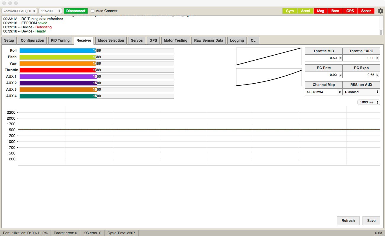
Notice the slight offset in the top four control signals? A little tweak and you can put those right on the '1500'. Night folks!
Discussions
Become a Hackaday.io Member
Create an account to leave a comment. Already have an account? Log In.