 seminolemuscle
Engineering is all about problem solving; not just creating solutions, but achieving them with very strict constraints in mind. The more restrictions you add, the more intricate and clever the solutions become. In the realm of the lean hardware startup, there are restrictions aplenty: cost, time, personnel, available tools, complexity — and the list goes on.
In this post, I’ll be stepping through the development of something seemingly simple that we would be flat-out screwed without: a chamfer tool.
The Problem:
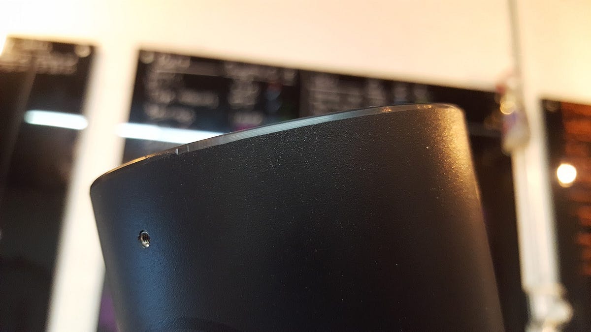
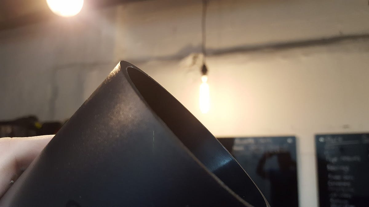
I was working on a project that required sourcing a single plastic injection molded part that was to be delivered to our local assembly operation. Our problem presented itself when our first batch of injection-molded housings arrived from our mold-house in Shanghai:

See any issues? Neither did I. It wasn’t until a colleague picked one up to create a full assembly that we discovered the terrible truth: “this bottom edge is waytoo sharp — we can’t sell this.”
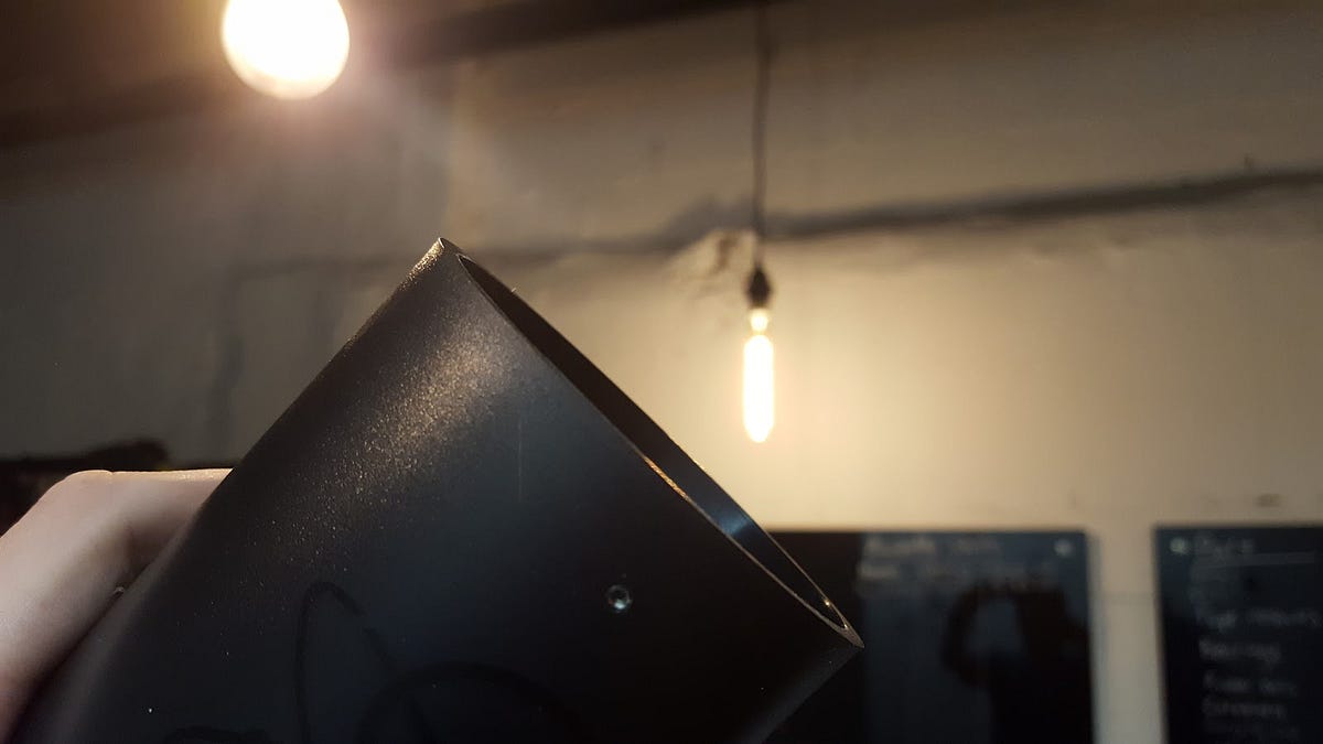
He was right. The edge was sharper than vermont cheddar — enough to potentially cut someone and needed to be dulled. I immediately checked the files I sent to the molder — our current model has a chamfer where it should; maybe the error was on their end and they’ll fix it for free?! Sadly, it was not. As it turns out, the culprit was a day’s lapse in version control and since the issue is a corner, the steel has already been drilled out of the mold and can’t be repaired. This problem is real and needs to be dealt with ASAP.
Brainstorming:
The options are few, really:
- Buy a free-hand chamfer tool
- Buy a pipe-chamfer tool
- Design and build a tool
Urgency determined that time took priority over cost, so we chose to try all three.
We quickly ordered a well-reviewed hand-tool with express shipping. We knew the chamfer would be a bit inconsistent, but replacement blades are cheap and a little practice from a skilled hand might produce acceptable results. Our tool came in and we gave it our best shot:

Yikes. Well, at least we know that’s off the table. It was a Hail Mary; we had much more confidence in Option B. Being that the diameter of our bottom edge is almost exactly 3 in, we figured that a pipe chamfer tool with variable standard diameters would do us justice.
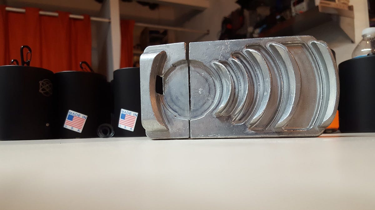
I popped on our housing and it sat pretty nicely on the inside edge. Not ideal, but it should suffice:
Nope, not quite. It makes sense that we need constant force against this blade or it’s going to skip. Also, the 15 degree chamfer is less than ideal; lengths where the chamfer is consistent are still pretty sharp and the metal lip of the tool leaves an undesirable line on the softer plastic. At this point we’ve exhausted the quick fixes within our budget. Time to do some engineering.
The Inspiration:
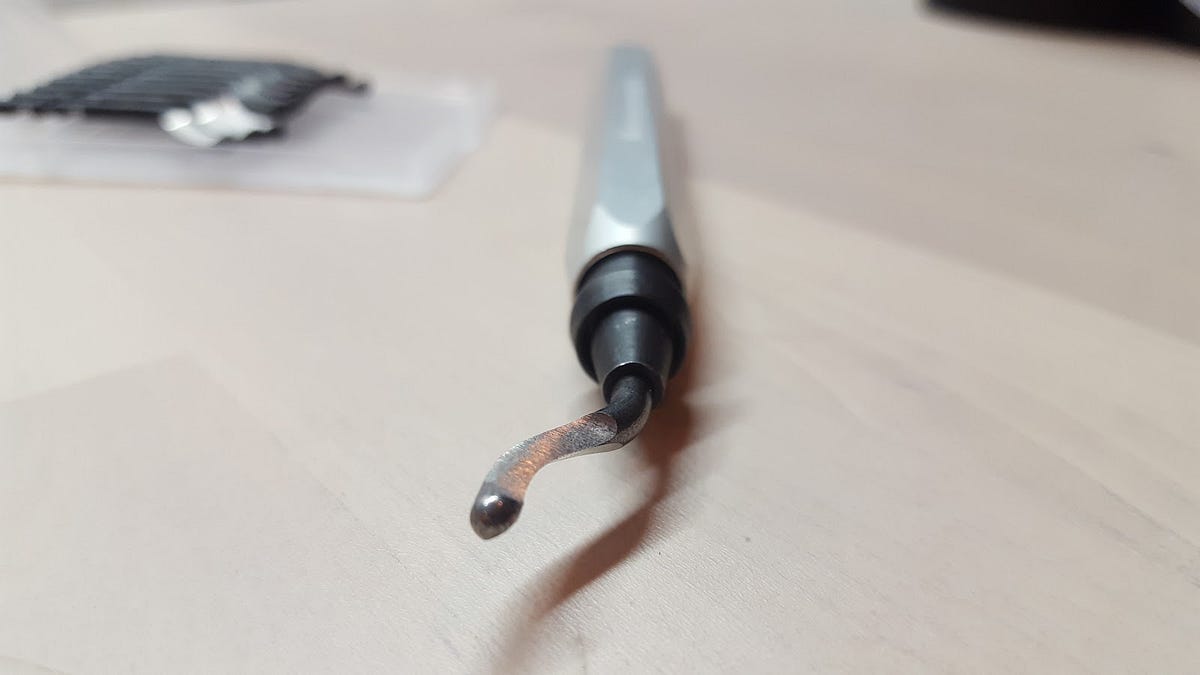
The pipe cutting tool has the right idea:
- A lip on both sides at the exact diameter of the housing will keep cuts smooth and consistent
- A flexible mending plate that attaches the blade portion to the backing will allow the housing a bit of wiggle room to snap into place snugly
- A sturdy, removable blade with a broad angle will allow us to shave off just the right amount of unwanted plastic
The decision was made simple: we redesign the tool with an exact, consistent diameter and more favorable blade angle out of something softer than our housing. Any parts we can reuse from our purchases should be incorporated for cost effectiveness. Time to get to work.
Rapid Design:
First things first, I took the dimensions of the cutting head so that, worst case, I could reuse it with my own backing lip.
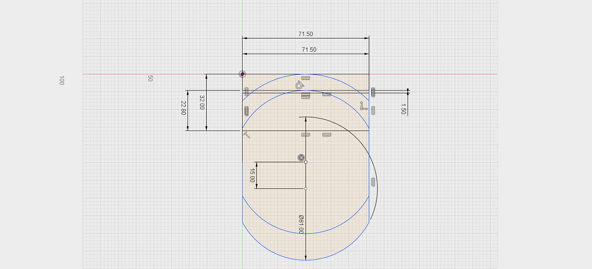
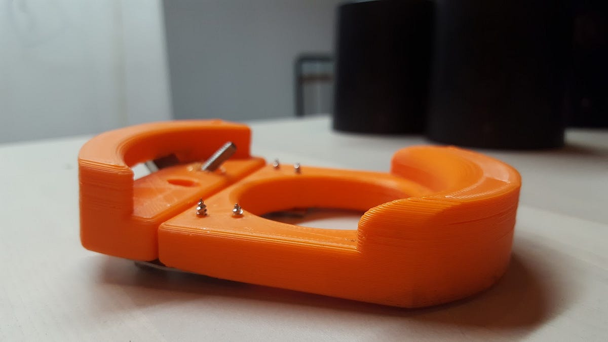
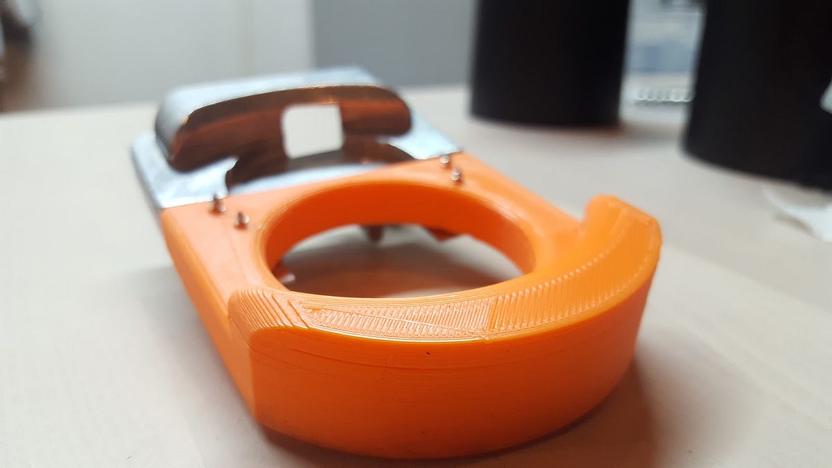
Next, I modelled a backing piece to attach to the current cutting head by making a sketch, extruding, and applying fillets to edges. I also cut a huge hole in the middle to save on printing time and plastic expenditure:
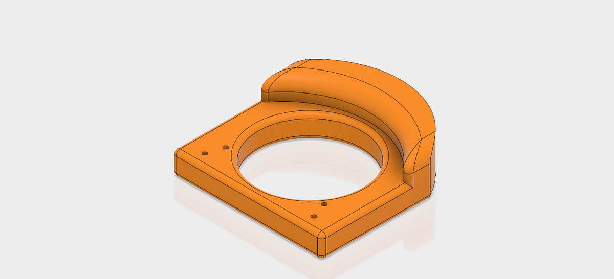
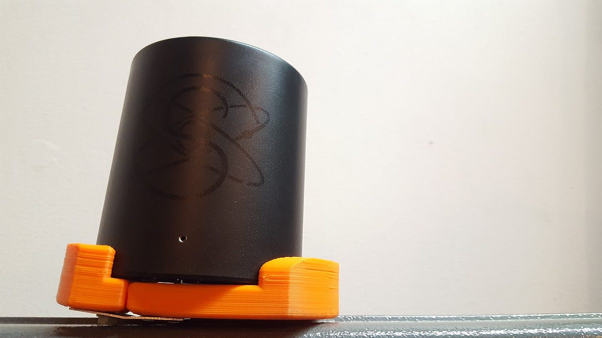
I pulled the model into Cura, maxed out the layer height for speed and gave a conservative 85% infill for strength. CTRL + P and some orange PLA and we ended up with this:
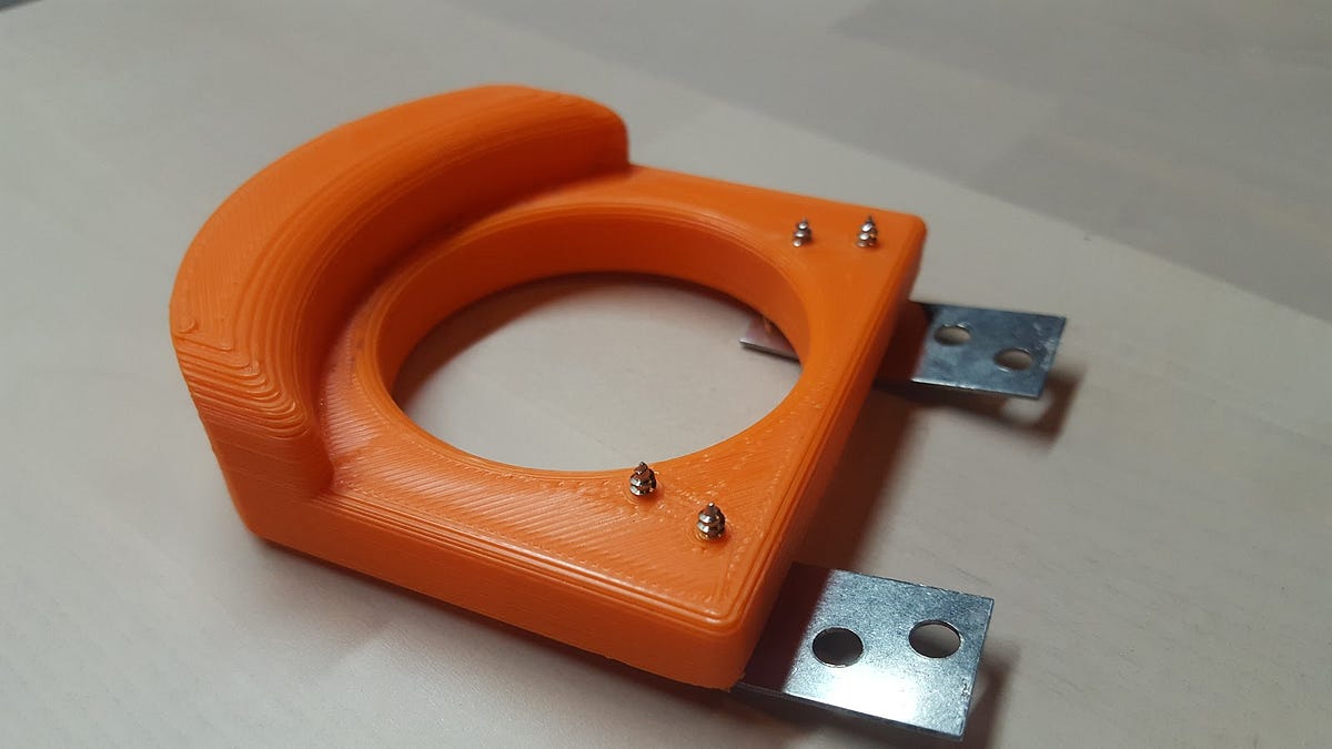
As expected, the print fits to the cutting head like a glove.
The Solution:
Time for the moment of truth:
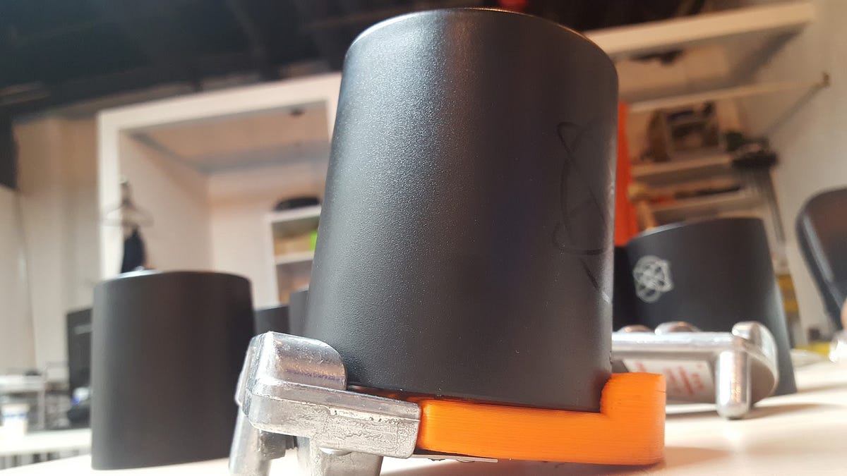
It cuts like a dream.
So now that we’ve validated the function of this design, it’s time to build a new cutting head with the correct chamfer angle. Back in Fusion, I’ve built up the cutting head portion, but with no gap for the blade. Since the wall thickness is 3mm, I’ve decided to cut half that from the housing.
I created a plane at 45 degrees from the back of the cutting head and extruding through until there was a 1.5 mm gap at the midpoint of the guiding lip’s arc.
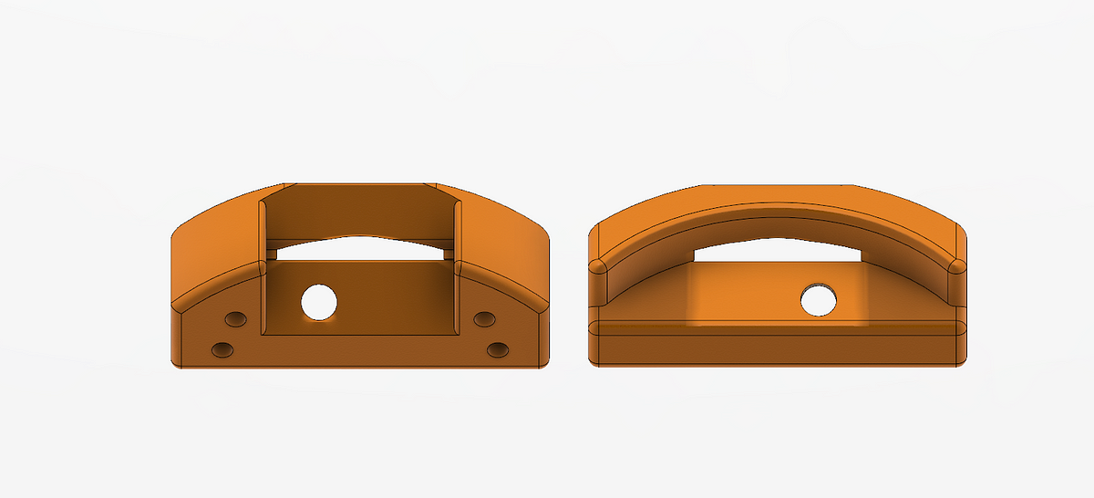
From there I added a hole for the blades screw, making sure that it cleared the inside of the housing (as it pokes through the other side), and added fillets everywhere. Same slicer settings as before and printing commenced.
Upon attaching the blade, I found that I created the hole on the wrong side so I made a new hole using a soldering iron — sure it’s not exact, but there are no rules here!
Attaching the blade was expectedly imprecise. It is crucial that the blade is flush with the back angle of the cutting head to create the correct chamfer. A bit of frowned-upon heat gun work and we’re in business:
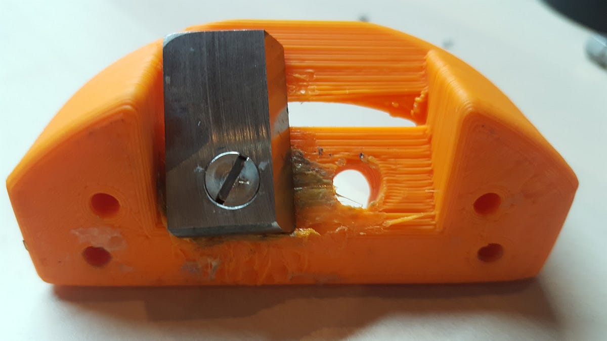
Mending plates are reattached and our custom chamfer tool is ready to face its final judgement.
I loaded the first housing in, closed my eyes, went to a tranquil place, and began to turn. To my surprise and delight, the plastic shaved away exceptionally. It took very little effort, and 5 seconds to go from this:
To this:
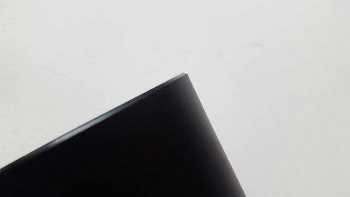
I tried a few more housings and the results are repeatable, consistent, and beautiful. Funny thing, that something so simple can be so satisfying.
All in all, we arrived at a befitting solution to our problem using ingenuity, some inspiration, and the tools that we had at our disposal. Not every technique was elegant and not every part was exciting. In the end, we produced something functional and essential without using unnecessary time, cost, or outside help.
Discussions
Become a Hackaday.io Member
Create an account to leave a comment. Already have an account? Log In.