0%
0%
Savin C2020 Teardown
When life gives you photocopiers...
 zakqwy
Become a Hackaday.io member
Already have an account? Log in.
Just one more thing
To make the experience fit your profile, pick a username and tell us what interests you.
Pick an awesome username
hackaday.io/
Your profile's URL: hackaday.io/username. Max 25 alphanumeric characters.
Pick a few interests
Projects that share your interests
People that share your interests
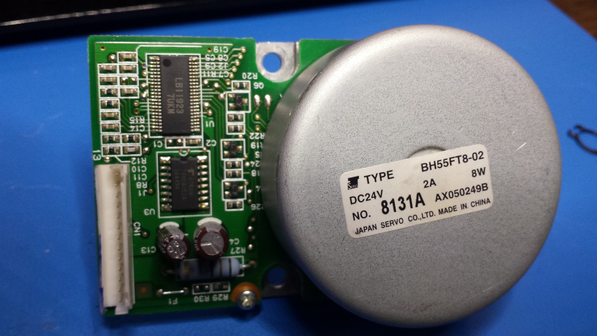
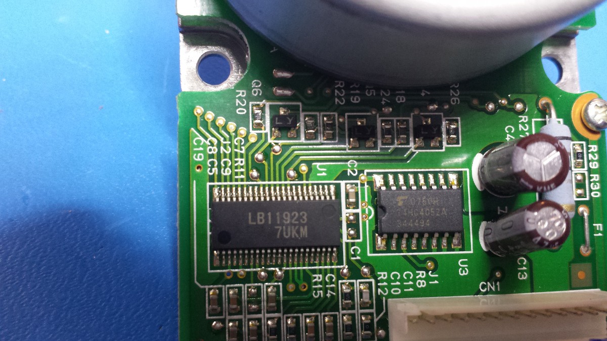
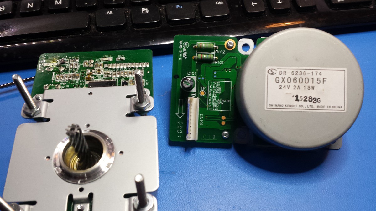
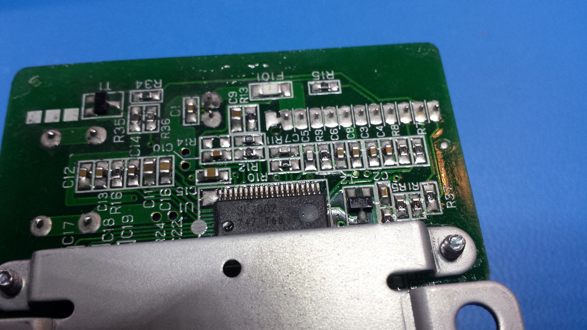
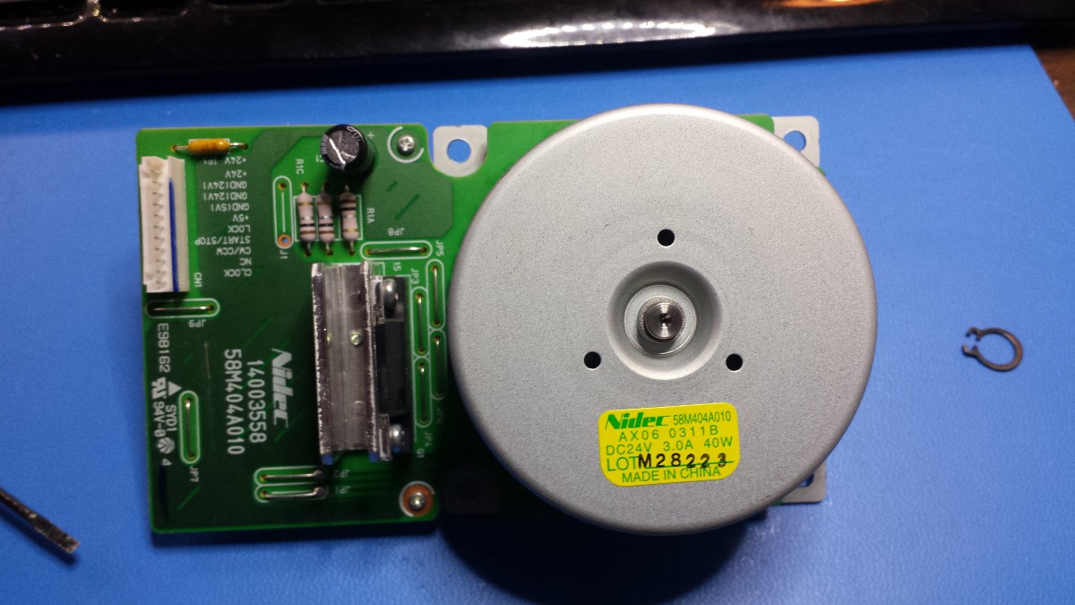
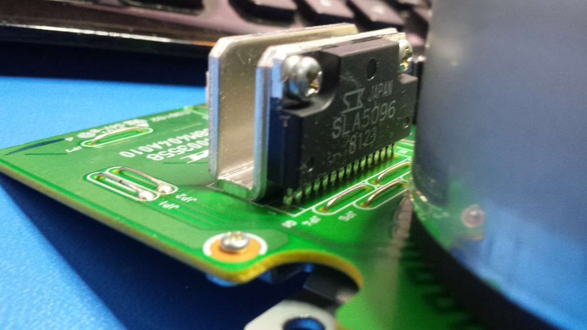
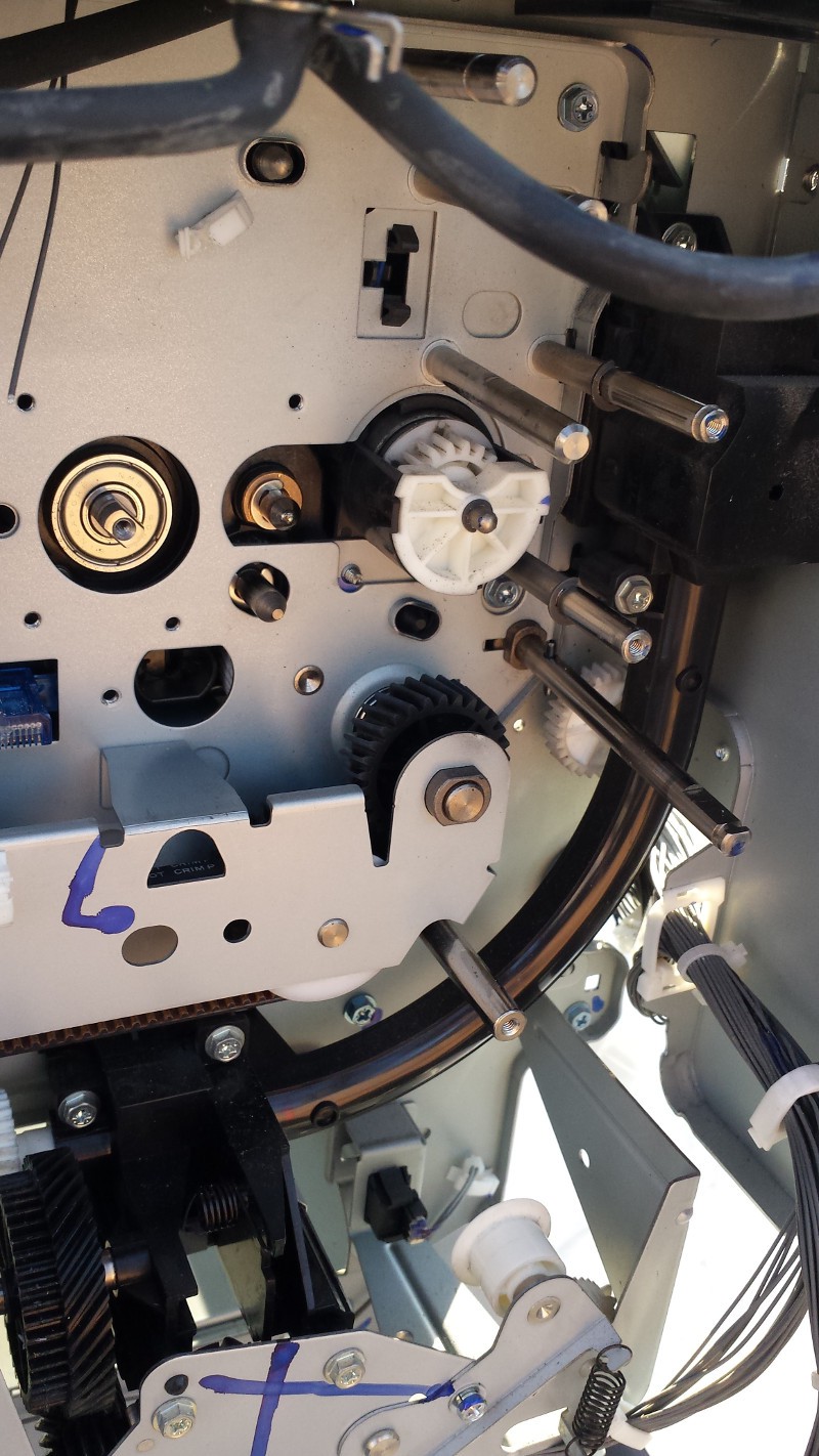
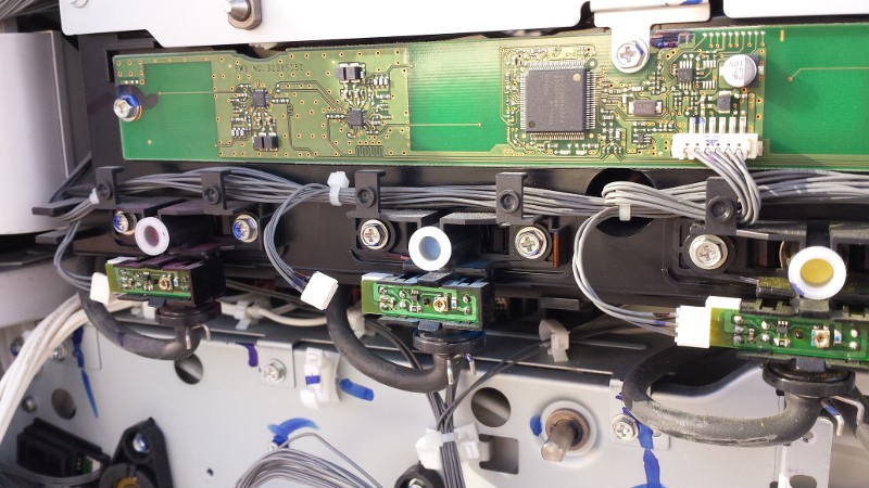
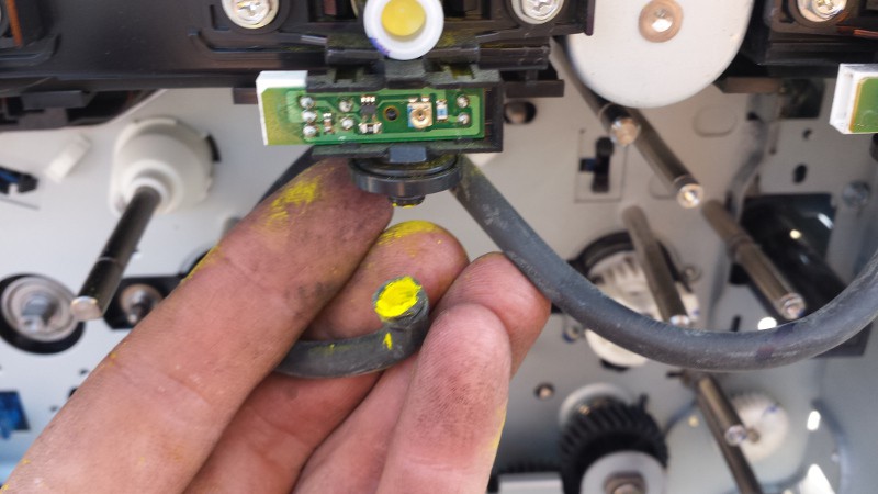
 Same driver chip as the smaller Japan Servo Co. unit, but no mux/demux visible (I suppose it could be hiding under the rotor):
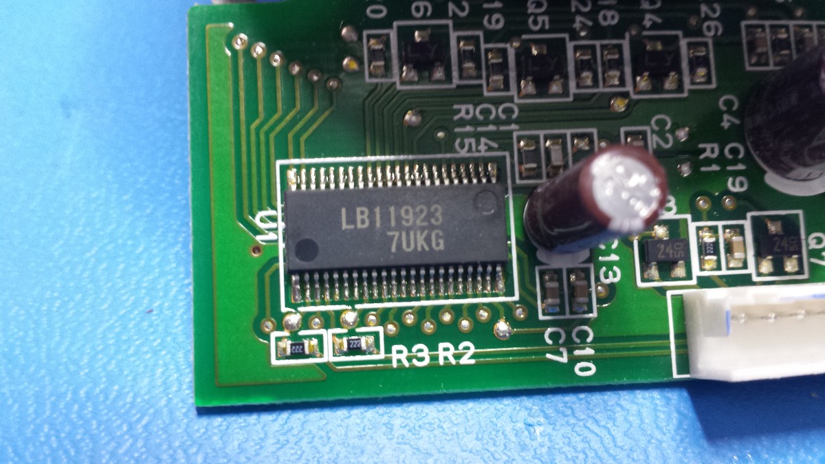


 Eric Hertz
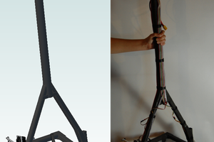

 Ossum
Ossum
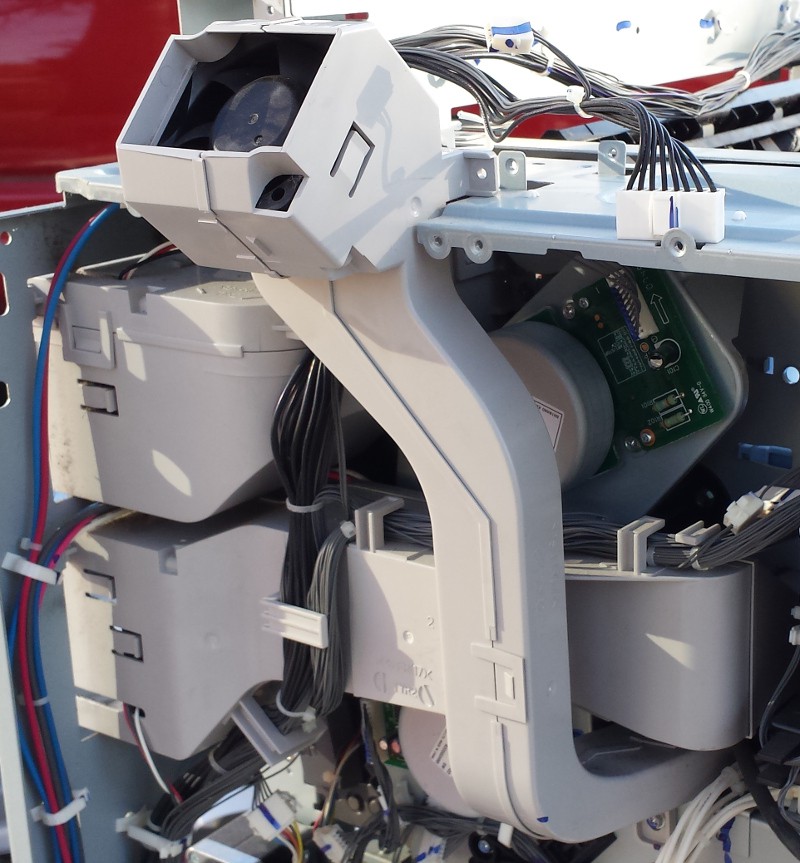
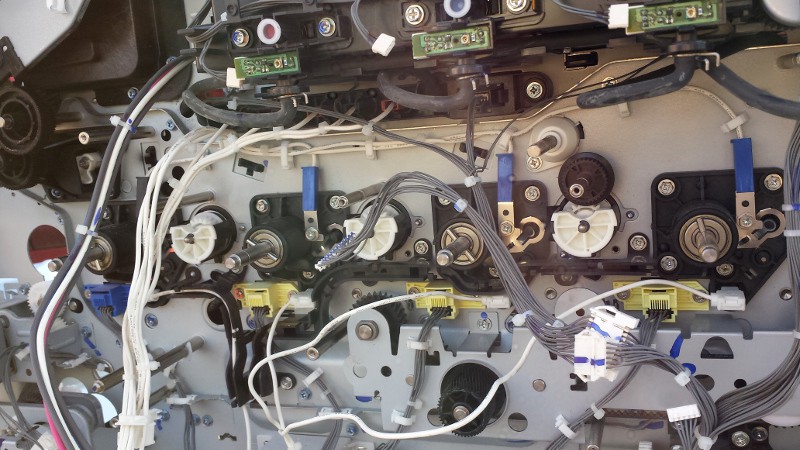
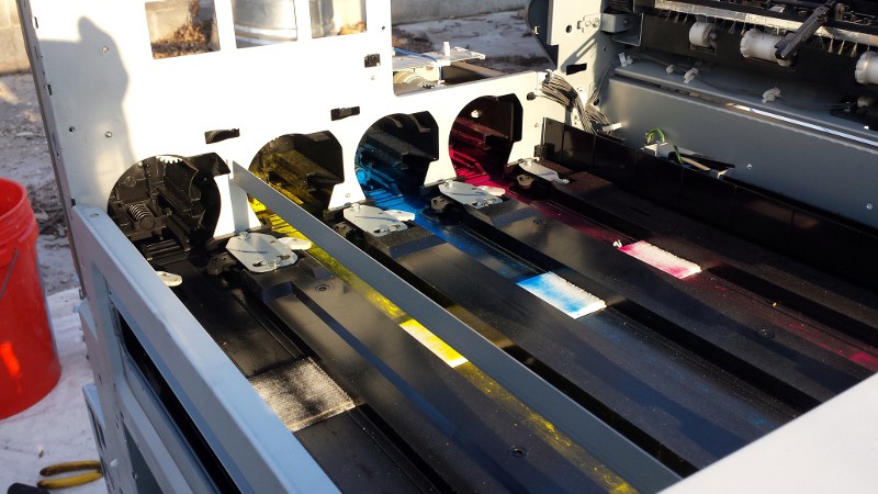
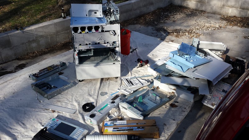
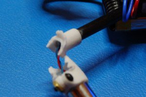
I used to be a savin tech, but only for b&w machines. My educated guess for the black hoses is that they are for waste toner. There was most likely a jug somewhere where they terminated.