 Technics
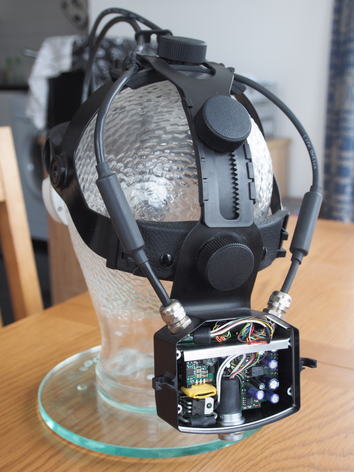
Okay it doesn't really have a warranty to begin with but I'd still prefer not to break it. Given the lack of information available it looks like it's time to tear this thing open. There are two major parts attached to the head mount. The microscope optics and mechanical components are in the front unit. The wiring from the front unit then connects to an enclosure at the back.
As attacking the front optical/mechanical unit seemed to carry the greatest risk (possibly affecting the alignment of parts or allowing the ingress of dust etc.) I have decided to start with the electrical connections at the back. According to the manual, this small enclosure is designed to hold an a counter weight to balance the unit so it is not too front heavy. Weights can be added or removed as required and are held in by a small bolt running through an internal bulkhead. However, this weight does not occupy the entire volume of the enclosure. The connections run behind this bulkhead. Removing it (held by four small screws) reveals the enclosures other purpose. It holds a considerable portion of the electronics that drive the microscope.
There are two stacked PCB's in this enclosure. The outer PCB contains what looks to be mostly power supply related circuity. It also has all of the electrical connections that run to the missing control box. The inner PCB is harder to see but at least one large IC is visible. The part number is obscured by a sticker that seems to indicate a firmware version so it is possibly a micro-controller.
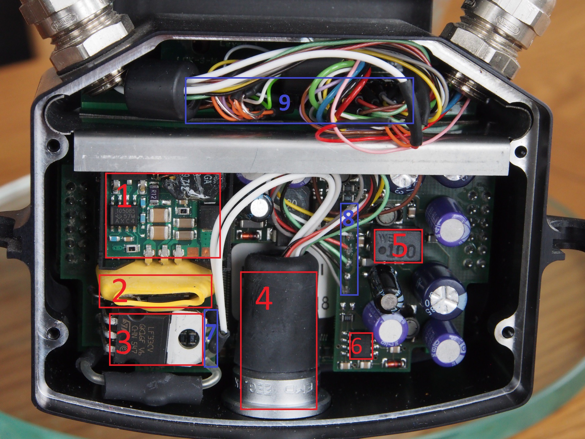
I've marked the interesting components in red and the external connections in blue.
- Unidentified module. Though it looks like a switch mode voltage regulator of some kind.
- Unknown module in yellow heat-shrink.
- ST LF33 3.3 Volt low drop-out linear voltage regulator
- 10 pin LEMO K-series connector for the control box.
- Wurth Electronics WE-SL2 common mode filter.
- Maxim MAX764 DC-DC inverter.
- A pair of shielded miniature coaxial cables terminated on the board (possibly S-Video)
- The other connections to the control box. These must include power and control signals.
- The connections to the front microscope motors and sensors.
It's worth noting that the grey and black wires from the control box are connected together by a trace on the PCB. The red and green wires are also connected together by a trace. This suggests that they may be the power connections. This is backed up by the observation that these two connections run through the common mode filter.
If the assumption about the mini-coax being for S-video is correct it really only leaves three wires (white, yellow and brown) for control of the microscope. The next step will be to attempt to power up the PCB and look at these signals on a scope to see if there is any activity.
Discussions
Become a Hackaday.io Member
Create an account to leave a comment. Already have an account? Log In.